1
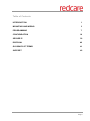
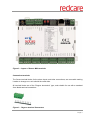
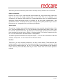
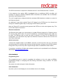
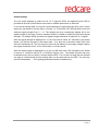
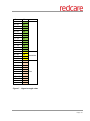
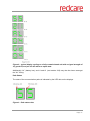
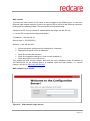
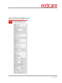
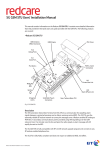
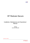
Redcare Secure Mk3 Installation, Maintenance and Operation Manual ModelSecMk3 Date: October 2012 Table of Contents INTRODUCTION 1 MOUNTING AND WIRING 3 PROGRAMMING 7 CONFIGURATION 16 SECURE IP 39 DISPOSAL 40 GLOSSARY OF TERMS 41 SUPPORT 42 October 2012 © British Telecommunications plc 2011 Page i INTRODUCTION Product Description Figure 1 - Secure Mk3 unit The Redcare secure Mk3 unit is a Dual path alarm signalling unit for transmitting alarm signals from a customer’s alarm panel, via the Redcare ESP network to an Alarm receiving Centre (ARC). The unit can be used in the GPRS/PSTN configuration for “Redcare secure 2/3” service, or the IP/GPRS configuration for “Redcare secure IP” service. The unit communicates via the Redcare Enterprise Services Network (ESP) and a valid TA account must exist for the unit to communicate. The TA account will have been populated with the serial number of the unit. The unit has 16 general purpose alarm inputs, and 3 outputs, making it suitable for connection to most common alarm panels. October 2012 © British Telecommunications plc 2011 Page 1 The unit is supplied already fitted with a Redcare enabled SIM card and is pre-configured to give GPRS connectivity. The unit is supplied pre-configured to connect to the Redcare network servers over PSTN 0800 dial up numbers or through IP tunnelled networking. Specifications Size: 119mm X 158mm X 28mm. Power: 9V – 30V Current: Mean Peak (during GPRS Tx) IP/GPRS unit @12V 124mA 150mA IP/GPRS unit @13.8V 106mA 127mA IP/GPRS unit @24V 68mA 79mA GPRS/PSTN @12V unit 107mA 134mA GPRS/PSTN @13.8V unit 92mA 117mA GPRS/PSTN @24V unit 64mA 78mA When an Ethernet connection is made to the unit then the current will be higher. (i.e. a GPRS/PSTN unit that has Ethernet connected for the purpose of accessing the web console will typically have similar current draw to that of an IP/GPRS unit. The above table assumes no add on daughter boards. Alarm inputs: 16 General purpose inputs 1-16. (-0.5V – 30V) Alarm threshold: High >2.5V +/- 0.02V, and Low <1.5V +/- 0.02V. Outputs: 3 X transistor outputs. 50mA max (active low). Internal 10K pullup. (Comms fail, RPS, CTRL) RS232 port: remote panel access (UDL) to some panel types. October 2012 © British Telecommunications plc 2011 Page 2 RS485 port: For future use. Expansion bus: For future use. (Dial capture Daughter board) Configuration: Using on board “Mode” and “Set” buttons, and or web console. Processor: Microchip dsPIC33EP512MU810 16 bit processor. Wireless module: Cinterion BGS2-E MOUNTING AND WIRING Removal of cover The top cover can be removed by inserting a screwdriver blade into the 6 slots at the top of the unit, and levering the plastic outwards to release the 6 clips. Regular access to the inside of the unit should not be required, although occasional access may be required to access the Sim card, or to add a daughter board for additional facilities. (i.e. dial capture board). The unit supports all Redcare enabled Sim types. (Redcare O2 / Redcare BT mobile / Redcare Roaming). The Sim type is auto detected by the unit without need for any configuration change. Mounting The unit should be mounted inside the alarm panel, or inside a separate powered housing, using the sticky mounting pads supplied. The back of the unit also supports DIN rail mounting for housings that support this type. The supplied aerial should be mounted on top of the outside of the housing by removing the adhesive backing. October 2012 © British Telecommunications plc 2011 Page 3 Figure 2 - Layout of Secure Mk3 terminals Connection terminals The Screw terminal blocks for the alarm inputs, and other connections, are removable making it easier to change out a unit should the need arise. All terminal blocks are of the “Degson electronics” type, and suitable for use with a standard 3mm blade terminal screwdriver. Figure 3 - Degson terminal Connectors October 2012 © British Telecommunications plc 2011 Page 4 When fitting the terminal blocks, please ensure that they are fully seated to the circuit board. Power connections Power to the unit is via 2 screw terminals at the bottom left, with positive being nearest the edge of the board. The supply voltage range is 9V to 30V. The unit is designed to be connected to the Auxiliary power output on an associated alarm panel, or separate powered enclosure. Ensure the power source is sufficient as per the power requirements in the specification section. Te account at the alarm receiving centre (ARC) should be put “on test” before power up, as signals will be sent following initialisation Alarm inputs The unit has 16 alarm inputs which are presented on screw terminals along the bottom of the unit. These are labelled as Pin 1-16. The first 8 alarm inputs also each have 0V and a ‘pos bus’ terminal associated with them. By default the 16 alarm inputs required a positive condition to be presented to send an alarm. (Default = Positive applied). This can be changed using the PL, P1 or P2 button menu. See later section on configuration. The alarm input terminal blocks are 4 way with inputs 1 – 8 on the last 2 connectors of the first 4 blocks, and inputs 9 – 16 are consecutive on the last 2 blocks. Pos Bus There are 4 pos bus terminals presented on the first 4 alarm blocks. These terminals are tracked together on the unit and can be used to provide more connection + points by wiring the first to the positive supply as per fig 4. The Pos Bus is also tracked to the expansion module sockets (J202 and J604) and may be further utilised with some future expansion modules. October 2012 © British Telecommunications plc 2011 Page 5 Figure 4 - utilising the Pos bus rail Outputs Three transistor outputs are provided on screw terminals at the top of the unit, and these have an associated 0V terminal on the 4th connector on the block. The outputs are transistor driven and use an internal 10K resistor to give the high state. By default, output 1 is comms Fail, output 2 is CTRL, and output 3 is RPS. See the further sections on outputs for a full explanation. Serial data connections RS232 TX & RX is also provided and RS485 A & B on another 4 way terminal block. These ports allow serial alarm panel connection. See Panel Upload Download section. PSTN connection The telephone line connection is made to a 2 way terminal block at the top right of the unit. The PSTN connection is not polarity sensitive. Connect the terminals to a standard PSTN line that supports DTMF outgoing access. October 2012 © British Telecommunications plc 2011 Page 6 The PSTN connection is required for “Redcare secure 2” and “Redcare secure 3” service. If the telephone line carries ADSL (broadband) then an additional ADSL microfilter will normally be required. Suitable hardwired ADSL microfilters are available from the Redcare web shop. www.Redcare.bt.com The unit is supplied pre-configured with the necessary 0800 telephone numbers to connect to the Redcare network. An additional 2 way block marked “Panel A B” allows for the PSTN line to be diverted out through an onboard bypass relay for carrying out PSTN dial in panel UDL. Note the “Panel A B” connection purely presents the PSTN out via the units bypass relay. This is not a dial Capture connection. Ethernet connection The Ethernet port needs to be connected to a suitable Ethernet network for “Redcare secure IP” service using CAT5 cable. For most IP installations, a standard Ethernet patch cable can be used. The Ethernet port can also be used to connect to a local PC for advanced unit configuration. This connection may require an Ethernet Crossover cable as the unit does not auto detect cable type. Aerial connection Connect the supplied aerial to the MMCX connector on the top left of the unit. The aerial should be placed in a position that receives the best wireless coverage for the GPRS network being used. Carry out a survey with a signal strength tester to establish the best location. If necessary, a selection of higher gain extension aerials can be purchased from the Redcare web shop at www.btinstallershop.com PROGRAMMING Programming Port The programming port is used for upgrading the software on the unit using a USBNav programming dongle, or analysing the units de-bug information using a USB to TTL serial cable (3V3). See section on serial de-bug for further information. Unit initialisation At power up the unit will display its current software level on the display. October 2012 © British Telecommunications plc 2011 Page 7 Figure 5 In the above example the display cycles 60 -41- 60 -11 -06 indicating that the software level is K60P41A60P11 Release Candidate 06 The unit will then immediately attempt to connect to the Redcare platforms over the configured paths. The unit will typically complete path establishment in the following times from power up. IP 40s GPRS 50s PSTN dial IP 40s Figure 6 - time to commission paths after unit power up The unit sends a “Unit Restarted” event (pin 984,1) over the first available path, followed by a “Unit restarted” restore (pin 984,3) within 2 seconds. The unit also sends the state of all 16 pins and the state of the PSTN voltage alarm and low Battery alarm. Sending these alarm states at start up help to ensure that the ARC alarm handling software reflects the true state of all pin alarms after start up. October 2012 © British Telecommunications plc 2011 Page 8 Status displays The unit clearly displays its status on the 2 X 7 segment LEDs. An additional green LED is provided at the side of the Ethernet connector to indicate packet flow on Ethernet. In its normal working state, the unit will cycle displaying the signal strength (SS), pins in alarm state (AL) and Grade of service (Gd) in 1s steps. i.e. It will show “SS” followed by the received wireless signal strength from 0 – 31. The display may also occasionally display 99 as the signal strength if the unit’s Cinterion wireless modem is unable to determine the current signal strength. For reliable GPRS operation the signal strength should be at least SS-12, or higher. After the signal strength is displayed for 1s, the unit will then show “AL” followed by any alarm inputs 1-16 that are currently in the alarm state. If no pins are in the alarm state, then it will show AL followed by 00. The unit may also show Lb (low battery) if the supply voltage is below the supply threshold, and t1 or t2 if test modes t1 or t2 are active. After the alarms status is displayed for 1s, the unit will then show “Gd” followed by the Grade of service i.e. Gd-04 for Secure IP, or Gd-02 for Secure 2 etc. The Grade of service can only be determined by the unit while in contact with the ESP. The unit will not show Gd until at least one path is commissioned and the polling rates can be retrieved from the ESP. The unit may show Gd followed by - - if the polling parameters cannot be determined. October 2012 © British Telecommunications plc 2011 Page 9 -dBm 57 - 58 59 - 60 61 - 62 63 - 64 65 - 66 67 - 68 69 - 70 71 - 72 73 - 74 75 - 76 77 - 78 79 - 80 81 - 82 83 - 84 85 - 86 87 - 88 89 - 90 91 - 92 93 - 94 95 - 96 97 - 98 99 - 100 101 - 102 103 - 104 105 - 106 107 - 108 109 - 110 111 - 112 SS 28 27 26 25 24 23 22 21 20 19 18 17 16 15 14 13 12 11 10 9 8 7 6 5 4 3 2 1 Borderline Poor Figure 7 - Signal strength chart October 2012 © British Telecommunications plc 2011 Page 10 Figure 8 - typical display cycling on a fully commissioned unit with a signal strength of 21, grade 04, and pin 4 in the alarm or open state. Additionally “bL” (battery low), and t1 and t2 (test modes 1&2) may also be shown amongst the “AL” listing. Path Status The state of the communication paths is indicated by the LED dots on the displays. Figure 9 - Path status dots October 2012 © British Telecommunications plc 2011 Page 11 The dot on the left display indicates the status of the wireline path, and the dot on the right is the status of the wireless path. The dot will be off when the communication path is unavailable. It will flash when the unit has obtained a suitable IP address during establishment, and will be steady on when the path has been fully commissioned. The dots will also briefly blink off when data is being passed over that link. i.e. each time the unit is polled then a brief blink is seen on the associated path dot. Also alarm transmission will be seen as a brief blink on the associated path dot. When fully commissioned over both paths, then both dots should be on. The meanings of the dots are somewhat similar to the path status Leds on previous secure units, and they also share some commonality with the dots on a Redcare 5G STU. The mnemonic “Left Landline” helps as a reminder as per 5G STU. Additionally, when representing the PSTN path, the left dot will blink to indicate “low PSTN voltage” and rapid flash to indicate PSTN communication to the platform is in progress. October 2012 © British Telecommunications plc 2011 Page 12 Left dot IP Right dot GPRS Left dot PSTN Off IP path to platform is not established GPRS path to platform is not established PSTN path has yet to establish, or last attempted PSTN call was unsuccessful Flashing An IP address has been obtained from the tunnel server. An IP address has been obtained from the GPRS Radius server. PSTN is in the process of dialling the platform N/A N/A PSTN call in progress and data is exchanging with the platform. On IP path now established to the platform. GPRS path now established to the platform. Last PSTN call attempt successfully communicated with the platform Blinking flash N/A N/A PSTN voltage has failed. (<3.5V). Polling or alarm data is passing across the IP path Polling or alarm data is passing across the GPRS path N/A 1s on 1s off Rapid flashing 250ms on 250ms 0ff 125 ms on 875 ms off Data blink 25ms off Figure 10 - LED path status indicator dots Of the 16 alarm pin inputs, all behave as general purposes inputs with the following exceptions. Pin 4 has the RPS output associated with it. (see output 3 RPS) Pin 11 acts as an ATS input as per the requirements of the BSIA form 175 document. This applies only when output 1 is set to BSIA mode (F8 =1). Pin 13 acts as an AC fail input and therefore has a default 7 minute delay before a pin 13 alarm is transmitted. It also has a 7 minute delay before a reset is sent. On presenting an alarm condition to pin 13, the units display will show the alarm immediately (AL 13) but 7 minutes of constant alarm condition needs to elapse before transmission. Similarly, a pin 13 October 2012 © British Telecommunications plc 2011 Page 13 restore will immediately remove the AL 13 from the display, but 7 minutes of constant restore condition needs to elapse before transmission of the pin 13 restore. The 7 minute time delay can be configured through the web console by typing a new value 0-7 in the “Mains Fail delay” field. If the “Mains Fail delay” is set to 0, then pin 13 can be used as a general purpose alarm input. (Subject to ARC acceptance). Output 1 Output 1 acts as the communications fail output. The mode of operation can be selected through the F8 button menu. (see config section) By default output 1 acts as a BSIA form 175 output. (F8=1). This allows the alarm panel to interrogate path faults as single path or dual path. That is, the output is normally low when both paths are OK. By default the output will switch high, following either path fail, once the relevant ‘debounce’ time has expired. (Defaults 2 minutes for IP, 15 minutes for GPRS and 15 minutes for PSTN) If ATS input (pin 11) is toggled during the fail period, i.e. (panel interrogation) then output 1 will either pulse low to indicate a single path failure, or remain high to indicate a dual path failure. The unit also supports inverted mode BSIA175 operation by learning pin 11 to be positive removed. Figure 11 - wiring to an alarm panel that supports single / dual path identification October 2012 © British Telecommunications plc 2011 Page 14 Output 2 Output 2 normally acts as a control output. This can be switched on and off by issuing the relevant telemetry command from the ARC. Telemetry request ID=0, Data=01 sets GPOP2 to low. ID=1, Data=01 sets GPOP2 high. Output 2 can also become a secondary path fail output if F8 is set to 4. In this case output 1 behaves as a primary path fail output, and output 2 as a secondary path fail output. Figure 12 - connecting a relay module to CTRL output 2. Note that the outputs sink current when low Output 3 Output 3 acts as a “Return Path Signalling” (RPS) output. The output is normally low, but will rise high when input pin 4 is triggered. It will return low when an acknowledge signal is returned from the Redcare server (ESP). The output has a October 2012 © British Telecommunications plc 2011 Page 15 minimum operation time of 1s. When the acknowledgement is received in less than 1 second after pin 4 is triggered then the output will remain high for 1s. This output can be inverted through the web console if required. CONFIRGURATION The unit is supplied pre- configured with factory default values. For most installations no changes to the configuration are required. The unit can either be configured by using the on-board Mode (M) and Set (S) buttons, or through a PC connected directly to the Ethernet port by surfing to the web console. Only limited configuration is available through the button method, and more advanced configuration requires web console access. Most installations will require no configuration changes, the unit being supplied ready for installation at default. A minority of sites may require minimal configuration changes at installation, and most of these will be achievable through the button config. i.e. Etc. Change the PSTN predial string. Change the interface combination from GPRS/PSTN to IP/GPRS Change the IP mode from dynamic to static, and allocate a address/subnet/and gateway address. Change the comms fail output type. static IP Button configuration The button configuration mode is entered by holding down the Mode (M) button for 3s. The unit will then display the first menu item PL. (Pin Learn) The configuration mode can be exited at any time, without saving changes, by holding down the M button for 5s. If a user gets lost within the menus then repeatedly pressing M will return to the main menu and eventually reach the ?? save option. When in the main menu, each press of the mode button will step to the next menu item down, and eventually return to the top of the menu. The full main menu options are shown in Fig. 13. Pressing the set (S) button on any menu item will enter the sub-menu and allow the function to be changed. Depending on the menu item will depend on the structure of the sub-menu. Typically, many menu items simply have the option to switch on or off. Where 0=Off and 1=On. In such menu items, the Set (S) button toggles the On / Off state, and the Mode (M) button returns to the main menu. October 2012 © British Telecommunications plc 2011 Page 16 Some menu items have more options. i.e. F8 has 4 options to set the comms fault output type. On such menus, the Set (S) button enters the sub menu, the set (S) button increments through the 4 options with each press, then the mode (M) button returns to the main menu. Some more complex menu items use the mode button to also step through additional levels in the sub menu. i.e. P1 sets the polarity of pins 1 to 8. The set button enters the P1 submenu. The S button toggles the polarity of pin 1, the M button increments to pin 2, where the S button can be used again to toggle the state. Each press of M will increment the pin, up to the last pin 8 and then return to the main menu. A similar process is used on the menu items that allow IP addresses to be input. Set button (S) enters the sub menu. Set button (S) then increments the first digit with each press. Mode button (M) increments to the next digit, where button S can again be used to set this value. The M button will increment through all digits 1-12 in the IP address. Some special characters are used on the displays. These are detailed in fig. 14. At any time the configuration mode can be exited, without saving changes, by holding down M for 5 seconds. October 2012 © British Telecommunications plc 2011 Page 17 Figure 13 - button configuration main menu options October 2012 © British Telecommunications plc 2011 Page 18 Figure 14 - special display characters October 2012 © British Telecommunications plc 2011 Page 19 Pin learn The polarity of pins can be learnt by the installer selecting the PL option on the button menu. Pressing Set (S) at PL will flash PL on the display to prompt “Are you sure?” Pressing Set (S) again will cause the unit to read the state of all 16 inputs and assume the current state is the normal (no Alarm) state. Pr will briefly be presented on the display as the new pin polarity config is written to flash memory. The unit will then restart. There is no requirement to “save the changes” after PL. Example – to learn the pin polarity : Access the button config menu by holding M for 3 seconds. PL is displayed Press S – the display now shows PL flashing for “Are you sure?”. Press S – the display shows Pr as the new polarities are stored. The unit restarts. At any time the configuration mode can be exited by holding down M for 5 seconds Test mode 1 (t1) Web console access To allow access to the web console, the t1 menu must be entered and set to 1. Access to the web console is then allowed. There is no need to save the change on the unit, simply use the Set (S) button to toggle the t1 value to 1 and then press mode (M) to return to the t1 main menu option. The unit will now have a static IP address of 192.168.222.222 for the duration that t1 is set to 1. This does mean that a unit configured for IP/GPRS will be unable to communicate across the IP path while in test mode 1. A comms fail on the IP path will therefore be signalled to ARC after the normal time out (normally 3 minutes). The GPOP1 output will also operate after the time out (normally 4 mins) indicating single path fail. This is considered normal. The GPRS path will still function OK while in test mode 1. i.e the unit will respond to incoming polls over GPRs and can be manually polled from the ESPUI if required. The PSTN path will also function OK while test mode 1 is enabled. i.e. new alarms presented to pins during test mode 1 can be sent over GPRS, or PSTN if required. They cannot be sent over IP. Test mode 1 will automatically exit after 20 minutes. Test mode 1 can manually be set back to 0 (off) at any time by the installer. Test mode 1 will revert to off if the unit is restarted. i.e. after clicking on the “save” button on the web console. See section on web console for further information. At any time the configuration mode can be exited by holding down M for 5 seconds. October 2012 © British Telecommunications plc 2011 Page 20 Test mode 2 (t2) Force alarms over secondary path. For test purposes an installer can set the unit to send all alarms over the secondary path. This is achieved by accessing the t2 menu and setting the value to 1. There is no need to save the change on the unit, simply use the Set (S) button to toggle the t2 value to 1 and then press mode (M) to return to the t2 main menu option. Test mode 2 is now active and all new alarms will be sent over PSTN on a PSTN/GPRS configured unit, or GPRS on an IP/GPRS configured unit. When test mode 2 is on, then incoming polls on the disabled path will still be responded to by the unit. Therefore the platform will not normally report a communications failure because of test mode 2 being active. Test mode 2 will automatically exit after 20 minutes. Test mode 2 can manually be set back to 0 (off) at any time by the installer. At any time the configuration mode can be exited by holding down M for 5 seconds. Example – to set test mode 2 on. All alarms sent over secondary path : Access the button config menu by holding M for 3 seconds. Repeatedly Press M until t2 is displayed. Press S – the display now shows the current t2 state. Where =0 is Off, and =1 is On. Press S to toggle the mode off and on. Where =0 is Off, and =1 is On. Press M to return to the t2 menu. (The test mode is now active) At any time the configuration mode can be exited by holding down M for 5 seconds. Pin Polarity (P1 & P2) The polarity of the pins can manually be configured by the installer. This is additional to the pin learn function described earlier. (P1 = pins 1 to 8 and P2 = pins 9 to 16) By accessing the config menu by holding (M) for 3 seconds, and then stepping with (M) to the P1 menu option, pressing set will enter the pin 1-8 sub menu. Polarity of pin 1 is displayed, and can be toggled with the (S) button. Further presses of (M) will step through all pins 1-8 showing their current polarity, and allowing each to be toggled to pos applied or pos removed with the (S) button. Once all 8 pins are set as desired then (M) will return to the main menu (P1). Note that any changes are not saved until the ?? option is accessed and (S) is pressed twice. Pins 9 – 16 can be checked or changed in a similar way be accessing the P2 menu. Note that the dot on the left display is on to distinguish pins 9-16 from 1-8. i.e. P2 menu has the left dot lit, while the P1 menu does not. The unit will reboot after the changes are saved at the ?? menu. October 2012 © British Telecommunications plc 2011 Page 21 Example – to configure pin 4 to be positive removed: Access the button config menu by holding M for 3 seconds. Repeatedly Press M until P1 is displayed. Press S – the display now shows pin 1 and its current polarity. Repeatedly press M until pin 4 is shown with its current polarity. Repeatedly press S until the required pin 4 polarity is shown. Repeatedly press M to scroll through the rest of the pins and then to the ?? (save changes question marks) Press S and the ?? will flash to prompt “Are you sure?” Press S and the unit will briefly display Pr (program) as the changes are written to flash. The unit will then restart. At any time the configuration mode can be exited, without saving changes, by holding down M for 5 seconds. Ethernet mode - Static / DHCP (F1). The function 1 (F1) button menu allows the unit to be changed between dynamic (DHCP client) or Static mode. When F1 is set to 0 (default) then the Ethernet port will attempt to obtain an IP address from a DHCP server on the LAN. When F1 is set to 1 then the Ethernet port can be configured with a static address by using the F2 / F3 and F4 menu functions. Example - To change the Ethernet mode: Access the button config menu by holding M for 3 seconds. Repeatedly Press M until F1 is displayed. Press Set – the display now shows the current mode. i.e. =0 for DHCP, or =1 for Static. Press S to toggle the value to the required setting. Press M to return to the F1 main menu. Repeatedly press M to scroll to the ?? (save changes question marks) Press S and the ?? will flash to prompt “Are you sure?” Press S and the unit will briefly display Pr (program) as the changes are written to flash. The unit will then restart. At any time the configuration mode can be exited, without saving changes, by holding down M for 5 seconds. Setting a static IP Address, Netmask and Gateway Address (F2 F3 and F4) It the secure unit is to be connected to a LAN that requires the unit to have a static IP address (i.e. no DHCP server on the LAN) then this can be configured as follows. Example - To set the unit to have the following address details:October 2012 © British Telecommunications plc 2011 Page 22 IP Address = 192.168.1. 56 Subnet mask = 255.255.255.0 Gateway = 192.168.1.254 Note that IP addresses are made up of 12 digits in 4 batches of 3, separated by dots. When the addresses are entered through the buttons they must be put in as 12 digit numbers, with zeros used to the left of each batch where necessary to pad out the addresses. i.e. IP Address = 192168001056 Subnet mask = 255255255000 Gateway = 192168001254 The digit number (1-12) will be shown on the left display, and its value on the right display. Access the button config menu by holding M for 3 seconds. Repeatedly Press M until F2 is displayed. Press S to enter the address submenu – the display now shows digit 1 and its value. i.e. 1 x. If necessary Press S to toggle the vale to the required setting. i.e 1 1 Press M to step to digit 2. The display now shows digit 2 and its value. i.e. 2 x. If necessary Press S to toggle the value to the required setting. i.e 2 9 Press M to step to digit 3. The display now shows digit 3 and its value. i.e. 3 x. o o If necessary Press S to toggle the value to the required setting. i.e 3 2 Continue using m to step to the next digit and S to set its value. (up to digit 12) Press M to return to the F2 main menu. If necessary – use a similar process to set the subnet mask in the F3 menu. If necessary – use a similar process to set the gateway address in the F4 menu. Repeatedly press M to scroll to the ?? (save changes question marks) Press S and the ?? will flash to prompt “Are you sure?” Press S and the unit will briefly display Pr (program) as the changes are written to flash. The unit will then restart. At any time the configuration mode can be exited, without saving changes, by holding down M for 5 seconds. Tunnel port (F5) When used in IP mode, the unit will attempt to establish a connection to the Redcare servers by signalling on IP Port 443. For most LANs this will function correctly, but on some advanced LAN configurations the network manager may not allow outgoing access on port 443 but 10443 may have outgoing access. Where this is the case then the unit can be configured to use the alternative port 10443. The Redcare servers are set to accept both ports and so no changes are required other than on the unit’s configuration. October 2012 © British Telecommunications plc 2011 Page 23 The alternative port can be selected by accessing the F5 menu. 0 = 443 (default) 1 = 10443 Example. Changing the unit to use Port 10443 Access the button config menu by holding M for 3 seconds. Repeatedly Press M until F5 is displayed. Press Set – the display now shows the current setting. i.e. =0 for 443, or =1 for 10443. Press S to toggle the value to the required setting. i.e. =0 for 443, or =1 for 10443. Press M to return to the F5 main menu. Repeatedly press M to scroll to the ?? (save changes question marks) Press S and the ?? will flash to prompt “Are you sure?” Press S and the unit will briefly display Pr (program) as the changes are written to flash. The unit will then restart. At any time the configuration mode can be exited, without saving changes, by holding down M for 5 seconds. Interface Combination (F6) The unit is supplied configured for primary path GPRS with secondary path PSTN. (Secure 2 and 3) The unit can be changed to primary path IP with secondary path GPRS. (Secure IP) This is carried out by changing the value of F6 in the button config. Example. Changing the unit to Secure IP. Access the button config menu by holding M for 3 seconds. Repeatedly Press M until F6 is displayed. Press Set – the display now shows the current setting. i.e. =0 for GPRS/PSTN, or =1 IP/GPRS. Press S to toggle the value to the required setting. i.e. =0 for GPRS/PSTN, or =1 IP/GPRS. Press M to return to the F6 main menu. Repeatedly press M to scroll to the ?? (save changes question marks) Press S and the ?? will flash to prompt “Are you sure?” Press S and the unit will briefly display Pr (program) as the changes are written to flash. The unit will then restart. At any time the configuration mode can be exited, without saving changes, by holding down M for 5 seconds. Note. The account on the Redcare servers must match the interface combination of the unit. Either IP/GPRS for secure IP, or GPRS/PSTN for secure 2/3. October 2012 © British Telecommunications plc 2011 Page 24 PSTN Pre-dial string (F7) The unit is supplied with the necessary telephone numbers to dial the Redcare servers when in PSTN mode. At some sites it may be necessary to add a predial number to the telephone number. i.e. a digit 9 to gain an outside line on a business line. A predial string of up to 8 digits can be configured through the F7 menu. Example. Changing the unit to dial 9 with a 1 second pause. Access the button config menu by holding M for 3 seconds. Repeatedly Press M until F7 is displayed. Press S to enter the predial sub menu. (the display shows the first predial digit 1 x) Repeatedly press S to step the first predial digit to 9. Press M to move to the second predial digit. (the display shows the 2nd predial digit 2 x) Repeatedly press S to step the 2nd predial digit to P for a 1 second pause. Press M to move to the 3rd predial digit. (the display shows the 3rd predial digit 3 x) Set the 3rd predial digit to blank. (this indicates the end of the predial string). Press M to return to the F7 main menu. Repeatedly press M to scroll to the ?? (save changes question marks) Press S and the ?? will flash to prompt “Are you sure?” Press S and the unit will briefly display Pr (program) as the changes are written to flash. The unit will then restart. At any time the configuration mode can be exited, without saving changes, by holding down M for 5 seconds. Tip. The predial special characters for * and # are shown on fig. 14. Tip. P will give a 1 second pause. Tip. The ‘close square bracket’ symbol tells the unit not to dial the leading zero on the telephone number. This is useful for using the unit outside of the UK, where an international dialling code may be required as the predial string. i.e. A predial string of 0044] may be used from some countries where 00 is the international access code. October 2012 © British Telecommunications plc 2011 Page 25 Comms Fail output mode (F8) Output 1 on the unit is a comms fail output. This is a transistor driven output that switches low. The unit has an integral 10K pull up resistor to pull the output high. See Outputs section for further information. The output can be configured for different modes of operation through the F8 button menu. Settings. F8 = 1 BSIA Form 175 mode F8 = 2 Standard comms fault 1 (either path failed) F8 =3 Standard comms fault 2 (both paths failed) F8 = 4 Output 1 = Primary path failed, Output 2 = Secondary path failed. Example. Changing the unit to use output 1 to indicate “Both Paths Failed” (F8=3). Access the button config menu by holding M for 3 seconds. Repeatedly Press M until F8 is displayed. Press Set – the display now shows the current setting. (as per list above) Press S to toggle the value to the required setting. i.e. =3 for both paths failed. Press M to return to the F8 main menu. Repeatedly press M to scroll to the ?? (save changes question marks) Press S and the ?? will flash to prompt “Are you sure?” Press S and the unit will briefly display Pr (program) as the changes are written to flash. The unit will then restart. At any time the configuration mode can be exited, without saving changes, by holding down M for 5 seconds. Load Defaults (Ld) The Ld option on the menu can be used to set the unit back to factory default. That is all settings will be reset to their standard values. The unit will revert to a standard configured GPRS/PSTN unit or IP/GPRS unit as supplied. Example. Setting the unit back to factory default. Access the button config menu by holding M for 3 seconds. Repeatedly Press M until Ld is displayed. Press S and the Ld will flash to prompt “Are you sure?” Press S and the unit will briefly display Pr (program) as the changes are written to flash. The unit will then restart. At any time the configuration mode can be exited, without saving changes, by holding down M for 5 seconds. October 2012 © British Telecommunications plc 2011 Page 26 Web console To access the web console a PC needs to be connected to the Ethernet port. A cross over Ethernet cable maybe required. Check for the green LED to the left of the Ethernet connector, blinking with the passing of data. This ensures the correct connectivity. Configure the PC to have a static IP address within the range 192.168.222.xxx. i.e. set the PC to have the following static details:IP address = 192.168.222.10 Subnet mask = 255.255.255.0 Gateway = 192.168.222.222. Access the button config menu by holding M for 3 seconds. Repeatedly Press M until t1 is displayed. Press S to access the submenu Press S to toggle the setting to 1 (web console enabled =1) Press M to return to the main menu. This enables the web console access, and gives the unit a temporary static IP address of 192.168.222.222 for the duration that t1 is enabled. Open the web browser, i.e. internet explorer, and surf to http://192.168.222.222. Web console Log in screen Figure 15 - Web console Login Screen October 2012 © British Telecommunications plc 2011 Page 27 Log in with username = admin, password = 348admin Web console main menu screen Fi Figure 16 - Web console Main Menu The menu has 3 items for simplicity. “Quick Start”, “Status and log”, and “Logout” October 2012 © British Telecommunications plc 2011 Page 28 Web console Quick Start Menu screen October 2012 © British Telecommunications plc 2011 Page 29 Figure 17 - Web console “Quick Start” page The web console “quick start” page in Fig. 17 is shown populated with the factory defaults. Clicking on the “Save Config” button, at the bottom of the screen, sends the configuration to the unit and then restarts the unit. Definition of quick start settings Account Information. Account number: Default = 0. This field can optionally be populated with the TA number of the device. Can be used to auto populate SID on the account at commission time. Agency ID: Default = 0. Normally always set to 0 Management Port: Default = 9000. Always set to 9000. Interface combination. Interface select: Default = Wireless + Dialup. This field enables the unit’s communication paths. Use “Wireless + Dialup” for “Secure 2 & 3” or “Wireline + Wireless” for “Secure IP” Wireline settings (IP path details) Server 1. Default 62.239.139.2 the address of the B side ESP servers. Server 2. Default 62.239.139.130 the address of the A side ESP servers. Server 3. Default = blank. Server 4. Default = blank. Tunnel Server port. Default = 443. The IP port used to establish the IP path tunnel. Can be set to alternative port 10443 if required by some IT system managers (see F5) Proxy server settings. The following settings are only required where direct Outgoing access is not available on IP port 443 or 10443, and the IT system manager requires all outgoing traffic to be routed via a proxy server. o Proxy IP:Port : Default = blank. Can be populated with the IP address and port of a proxy server if required by some IT system managers. o Proxy Auth type: Default = None. Can be set to None, basic or NTLM if required by some IT system managers. o Proxy User: Default = blank. Username for a Proxy server where required. o Password: Default = blank. Password for the Proxy server where required. LAN settings DHCP. Default = ticked. The unit will automatically obtain its IP addressing details from a DHCP server on the LAN. Untick to turn off DHCP where static IP addressing is required by the IT system manager. October 2012 © British Telecommunications plc 2011 Page 30 IP Address: Default = Last used IP address e.g. 192.168.1.15. Can be set to a static IP address where required by the IT system manager. Auto populated if DHCP is enabled. Subnet mask: Default = Last used subnet mask e.g. 255.255.255.0. Can be set to a static IP mask where required by the IT system manager. Auto populated if DHCP is enabled. Gateway address: Last used gateway address e.g. 192.168.1.254. Can be set to a static gateway address where required by the IT system manager. Auto populated if DHCP is enabled. Primary DNS: Default = Last used DNS address e.g. 192.168.1.254. Can be set to a static DNS address where required by the IT system manager. Auto populated if DHCP is enabled. Secondary DNS: Default = Last used DNS address e.g. 0.0.0.0. Can be set to a static DNS address where required by the IT system manager. Auto populated if DHCP is enabled. Wireless Interface settings. (GPRS) Server 1. Default 10.18.43.211 the address of the A side ESP servers. Server 2. Default 10.18.43.195 the address of the B side ESP servers. Server 3. Default = blank. Server 4. Default = blank. Username. Default = redcare.bt.com. The GPRS network username. Only used if Sim override = Off. Password. The GPRS network password. Only used if SIM override = Off. APN. The GPRS APN. Only used if SIM override = Off. Smart roaming. Default = ticked. Use smart roaming if supported by the SIM when ticked. SIM Overide: Default = Presets 1. Automatically detect the sim type and use the hard coded GPRS settings that match. Off = use the GPRS settings in the above (Username/ password/APN) fields. Roaming CSQ limit. Default = 19. Following unit startup, if the signal strength is less than this value, then roam through the available networks until this value is exceeded or all available networks have been attempted. (CSQ19 = -75dB). Roaming Session limit. Default = 8640 (minutes). If the previous GPRS session was longer than this time then the roaming algorithm will initially try to re-connect to the previous network. Else the unit will try the next available network. (8640mins=6 days). Dial Up settings. Server 1. Default 10.18.43.195 the address of the B side ESP servers. Server 2. Default 10.18.43.211 the address of the A side ESP servers. Server 3. Default = blank. Server 4. Default = blank. October 2012 © British Telecommunications plc 2011 Page 31 Predial number; default = blank. Any additional digits that may be required to be dialled. i.e. 9 to obtain an outside line on PABX, 1740 to force CLI on, 1280 to force BT routing. Phone Number 1. Default = 08009173263. Telephone number of A side ESP servers. Phone number 2. Default = 08009173265. Telephone number of B side ESP servers. Username. Default = [email protected]. Username for dialup RAS Password. Password for dial up RAS. Voltage fail delay. Default = 120s. Delay time before loss of PSTN voltage is reported. (Pin 955 alarm). Also delay time before GPOP1 operates for loss of PSTN voltage. Voltage restore delay. Default = 30s. Delay time before restore of PSTN voltage is reported. (Pin 955 restore). Also delay time before GPOP1 restores for restoration of PSTN voltage. Panel settings Panel type. Default = Pin. Future use will enable dial capture module. Kiss Off window. Default = 0 ms. Future use allows dial capture kiss off time to be extended. Off line timeout. Default = 1500 minutes. Unit will reboot if no polls are received from ESP over any path for this period of time. (1500mins = 25 hours) Mains Fail time. Default = 7 minutes. Time delay before pin 13 alarm is reported. Low DC fail time. Default = 1 minute. Time delay before Low supply voltage alarm is reported. (pin 985 alarm) General Purpose input sense settings. Tick for positive applied triggering. Untick for positive removed triggering. Inputs 1-8 Inputs 9-16 Line Fault Debounce time. Wireline. Default = 2 mins. Time before GPOP1 will operate following IP path failure. Wireless. Default = 15 mins. Time before GPOP1 will operate following GPRS path failure. Dial IP. Default = 15 mins. Time before GPOP1 will operate following PSTN path failure. (Note: GPOP1 will restore immediately following path restoral). General Purpose Outputs. GPOP1. Default = BSIA form 175. o BSIA form 175. Operate on either path fail, and respond to panel interrogation on pin 11. October 2012 © British Telecommunications plc 2011 Page 32 o BSIA o Standard line Fault 1. Operate on either path fail. o Standard line fault 2. Operate on both paths fail o Primary path fault. Operate when the primary path fails. (use with GPOP2). GPOP2. Default = Relay 2 control. o Relay 2 control o Secondary path fault. (use with GPOP1). GPOP3. Default RPS (Return path signalling) GPOP1-3 sense. Default = all ticked. Tick for low when normal and high when operated. Untick for high when normal and low when operated. Web console status and log screen Figure 18 - Web Console “Status and log” screen The status and log screen shows the current system status, and access to the unit’s event history. The Event log history is extensive and will go back further than the last unit re-start. (i.e. the event history is stored in flash memory and not cleared by loss of power). The event log will store a minimum of 1025 events. Events that are generated while the time on the unit is not set, i.e. after the unit has been powered up but before the unit has communicated with the ESP to obtain the correct time, are time stamped with the pseudo time and date in the year 2000 as per Fig. 18. Note that events logged while the unit’s time has been synchronised will use Greenwich Mean Time (GMT). October 2012 © British Telecommunications plc 2011 Page 33 When a PSTN call is attempted and fails to establish, a “Fail to communicate” event is logged in this local log. For further debugging there is a “Device number” associated. i.e. Device 0/2 means the unit failed to dial the second telephone number. Other typical messages that may appear in the log. Telephone line restore. Device 0 PSTN has successfully dialled up after a fail. Fail to communicate. Device 0/1 PSTN call to Telephone number 1 failed Fail to communicate. Device 0/2 PSTN call to telephone number 2 failed Panel upload Download. Remote access to the alarm panel can be achieved using the redcare UDL facility. Contact your redcare representative for details of accessing the redcare UDL servers. Figure 19 - serial connection to Galaxy panel allowing remote panel access from Galaxy Remote Service Suite Roaming SIMs The unit will auto detect the sim type that is present in the unit. Most units are supplied pre fitted with a Roaming Sim. Where a Roaming Sim is fitted then the unit will switch between GPRS networks to maintain connectivity should connectivity be lost on the current network. The unit will search the available networks for a signal stronger than the “Roaming CSQ limit” at unit start up. (Default 19) October 2012 © British Telecommunications plc 2011 Page 34 Should the unit lose connectivity with the Redcare platforms, or lose registration with the current base station, then the unit will roam onto the next available GPRS network. Remote commands to the unit The ARC can issue telemetry commands to the unit, with the ID and Data fields set as below to perform the listed functions. Function ID Data Switch GPOP2 (CTRL) High 0 01 Switch GPOP2 (CTRL) Low 1 01 Perform a F175 path test (event and restore 1 cycle) 00 Operate the PSTN to Dial cap bypass relay 1 (Offline) 02 Release the PSTN to Dial cap bypass relay (On 0 line) 02 Figure 20 - reverse telemetry commands from ARC The ARC can also poll the unit over GPRS or IP to check that the path is currently available. Additionally, Redcare helpdesk staff can access the following commands. Manual Poll to the unit over IP or Wireless. Retrieve the wireless details from the unit. Operate or release the PSTN to Dial cap bypass relay. (Offline/online) Send a test alarm. (user test). Send a dual path test. (F175 test) Restart the unit. October 2012 © British Telecommunications plc 2011 Page 35 Alarm List Description Low DC Level Pin Input 985 CID (zone) SIA (zone) FF (zone ) Time to Active 302 (999) YT/YR 6 (2) E – 1 minute; R – 1 minute PSTN voltage fail 955 356 (999) LT/LR 6(5) E – 120s; R – 30s Inputs 1-16 116 323 UA/UR (901-916) 7 (1) E – Immediate; Immediate R – BSIA 175 Test 988 354 (998/999) TX/TE 6 (3) E – Immediate; Immediate R – Unit Restarted 984 305 (995) AT/AR (995) 5 (6) E – Immediate; Immediate R – Panel Download 993 LB/LX (999) E – Bypass on; R – Bypass off User Test n/a TX(998) E – Immediate. (901-916) Figure 21 - alarms signals as delivered to ARC October 2012 © British Telecommunications plc 2011 Page 36 Secure IP (Grade 4 only) specification notes IP Protocol: TCP Port: 443 or 10443 Data Usage / Requirements Secure IP Grade 4 polling is every 30 seconds. A poll and response results in 288 total bytes transferred (incl IP headers). A small number of alarms will also typically be generated per day and these result in 296 bytes transferred. Overall this generates approximately 800 K Bytes per day, per site. Traffic Direction Secure IP establishes an outgoing TCP connection from your network to the Redcare Enterprise Services Platform (ESP). Once this outgoing TCP connection has been established, traffic over that connection is 2 way. Additional Protocols Only TCP is required from your network. Port Forwarding No ports need to be forwarded in the incoming direction. The outgoing TCP connection connects to port 443 or 10443 on the Redcare ESP network, so you would need to allow outgoing access to port 443 or 10443 if you block that by default. NAT: Not required GPRS Requirements You do not need to route GPRS traffic. The GPRS connection from the Secure IP communicator through to the Redcare ESP and on to the ARC is entirely independent of your network. DHCP and Static Addressing The Secure IP communicators can be configured as either DHCP clients or with specific static IP addresses on your internal network as you prefer. October 2012 © British Telecommunications plc 2011 Page 37 Disposal The symbol shown here and on the product, means that the product is classed as Electrical or Electronic Equipment and should not be disposed of with other household or commercial waste at the end of its working life. The Waste Electrical and Electronic Equipment (WEEE) Directive (2002/96/EC) has been put in place to recycle products using the best available recovery and recycling techniques to minimise the impact on the environment, treat any hazardous substances and avoid the increasing landfill. Product disposal instructions for users: Please dispose of the product as per your local authority’s recycling processes. For more information please contact your local authority or retailer where the product was purchased. The product may be returned to the Freepost address below: BT SUPPLY CHAIN DARLINGTON ROAD , NORTHALLERTON. NORTH YORKSHIRE DL6 2PJ. Republic of Ireland customers can return the product to any of the following addresses: BT IRELAND BT IRELAND BT IRELAND 27 WILLSBOROUGH INDUSTRIAL GRAND CANAL PLAZA DUNDRUM BUSINESS PARK ESTATE GRAND CANAL DOCK DUNDRUM CLONSHAUGH DUBLIN 2 DUBLIN 14 DUBLIN 17 Disclaimer The manufacturer or his agents disclaim responsibility for any damage, financial loss or injury caused to any equipment, property or persons resulting from any use of this equipment. The manufacturer is not liable for any purely economic loss arising from any use of this equipment. All responsibility and liability in the use of Redcare products are assumed by the user. This unit is designed to be used in customer premises. Use of this equipment in other locations may void warranty. This unit is not intended for use in marine environments or water borne vessels. Redcare may make changes to features and specifications at any time without prior notification in the interest of ongoing product development and improvement. October 2012 © British Telecommunications plc 2011 Page 38 Glossary of terms ADSL Asymmetric digital subscriber line (Broadband) ARC Alarm receiving Centre BSIA British Security Industry Association BER Bit Error Rate (0-7, normally shown as 99 on Secure Mk3) CSQ Carrier Signal Quality (RSSI,BER) CTRL Control O/P (remotely controlled output) DHCP Dynamic Host Configuration Protocol DIN Standard mounting rail for control equipment. (Deutsches Institut Fur Normung). DNS Domain Name Server ESP Enterprise Services Platform (Redcare’s new generation alarm signalling network) ESPUI Enterprise Services Platform User Interface. (Redcare’s user interface) F175 Form 175 as issued by BSIA GMT Greenwich Mean Time GPIP General Purpose Input GPOP General Purpose Output GPRS General Packet Radio Service IP Internet Protocol LED Light Emitting diode (Light Indicator) LAN Local area Network MMCX Micro Miniature Coaxial connector NTLM NT Lan Manager - a suite of Microsoft security Protocols TTL Transistor Transistor Logic Tx Transmit PABX Private Automatic branch Exchange. (Telephone system) October 2012 © British Telecommunications plc 2011 Page 39 PIN Parallel Input PSTN Public switched Telephone Network RAS Remote Access server RSSI Received Signal strength indicator (0-31) RPS Return Path Signalling (An output that confirms delivery of PIN 4 to ESP) Rx Receive SID Serial Identity number - 12 digit unique identity number of a secure unit SIM Subscriber identity module (sim card) USB Universal Serial Bus USBNav USB Programming tool for secure Mk3 Support For assistance with your Redcare Secure installation, please contact the Redcare Helpdesk on 0800 671 240 option 5. October 2012 © British Telecommunications plc 2011 Page 40