1
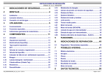
A ASSC CEEN NTTA AD DW WR REEPPA AIIR R IIN NSSTTR RU UC CTTIIO ON N 4.7 Water inlet valve.........................................................11 4.8 Door latch ...................................................................12 4.9 Terminal block............................................................12 4.10 Drain hose ..................................................................12 4.11 Dispenser....................................................................12 INSTALLATION ...................................... 3 4.12 Aqua sensor ...............................................................13 2.1 Pre-Install checklist .....................................................3 4.13 Display and power modules......................................13 2.2 Alignment .....................................................................3 4.14 Hose system...............................................................13 2.3 Electrical connection ...................................................3 4.15 Backflow valve ...........................................................14 2.4 Water connection .........................................................4 4.16 Sump parts .................................................................14 2.5 Drain and condensation hose connections...............4 5 REPAIR................................................. 15 3 OPERATION ........................................... 5 5.1 Front & bottom access ..............................................15 3.1 Control layout...............................................................5 5.2 Left side access .........................................................15 3.2 Using controls..............................................................5 5.3 Right side access (power module) ...........................15 3.3 Reset (“Cancel – drain”)..............................................5 5.4 Fascia panel disassembly .........................................16 3.4 Changing basic settings..............................................5 5.5 Heat pump disassembly ............................................17 3.5 Special programs (codings)........................................7 5.6 Float (safety system) .................................................17 3.6 Sales demo (showroom) program ..............................8 5.7 2-piece drain hose connection .................................18 4 COMPONENTS....................................... 9 6 FAULT DIAGNOSTICS......................... 19 4.1 Tank with base and sump ...........................................9 6.1 Fault codes (service / customer) ..............................19 4.2 Heated circulation pump (heat pump)........................9 6.2 Customer service test program ................................23 4.3 Float ............................................................................10 6.3 Troubleshooting.........................................................26 4.4 Drain pump .................................................................10 7 TECHNICAL SPECIFICATIONS .......... 27 4.5 Water inlet / condensation system ...........................10 4.6 Door spring.................................................................11 1 SAFETY .................................................. 2 1.1 General hazards ...........................................................2 1.2 Electrical shock / fire hazards.....................................2 1.3 Plumbing / scalding hazards.......................................2 2 702_58300000130262_ara_en_b Page 1 of 27 1 SAFETY 1.1 General hazards m Don’t use the dishwasher until it is completely installed. When opening the door on an uninstalled dishwasher, carefully open the door while supporting the rear of the unit. Failure to follow this warning can cause the dishwasher to tip over and result in serious injury. In some conditions, hydrogen gas can form in a hot water system that has not been used for weeks. Hydrogen gas is explosive. Before filling a dishwasher from a system that has been off for weeks, run the water from a nearby faucet in a well ventilated area until there is no sound or evidence of gas. Temperatures required for soldering and sweating will damage the dishwasher’s base and water inlet valve. If plumbing lines are to be soldered or sweated, keep the heat source at least 6 inches (152.4 mm) away from the dishwasher’s base and water inlet valve. Removing any cover or pulling the dishwasher from the cabinet can expose hot water connections, electrical power and sharp edges or points. Handle with care. Always wear gloves and safety glasses. 1.2 Electrical shock / fire hazards c h Don’t allow electrical and water supply lines to touch. Don’t work on an energized circuit. Doing so could result in serious injury or death. Only qualified electricians should perform electrical work. Don’t attempt any work on the dishwasher electric supply circuit until you are certain the circuit is de-energized. Make sure electrical work is properly installed. There should be no loose electrical connections. Ensure all electrical connections are properly made. 702_58300000130262_ara_en_b The customer has the responsibility of ensuring that the dishwasher electrical installation is in compliance with all national and local electrical codes and ordinances. The dishwasher is designed for an electrical supply of 120VAC, 60 Hz, connected to a dishwasher-dedicated, properly grounded electrical circuit with a fuse or breaker rated for 15 amps. Electrical supply conductors shall be a minimum #14 AWG copper only wire rated at 75°C (167°F) or higher. This appliance must be connected to a grounded metal, permanent wiring system, or an equipment-grounding conductor must be run with the circuit conductors and connected to the equipment-grounding terminal or lead on the appliance. Don’t use extension cords. 1.3 Plumbing / scalding hazards m Don’t perform any work on a charged hot water line. Serious injury could result. Only qualified plumbers should perform plumbing work. Don’t attempt any work on the dishwasher hot water supply plumbing until you are certain the hot water supply is shut off. Don’t over tighten the 90° elbow. Doing so may damage the water inlet valve and cause a water leak. Temperatures required for soldering and sweating will damage the dishwasher’s water inlet valve. If plumbing lines are to be soldered or sweated, keep the heat source at least 6 inches (152.4 mm) away from the dishwasher’s water inlet valve. Check local plumbing codes for approved plumbing procedures and accessories. All plumbing should be done in accordance with national and local codes. These instructions depict an installation method for stainless steel braided hose or PEX hot water supply lines. If using copper tubing or other material for water supply, defer to a licensed plumber for proper installation. Page 2 of 27 2 INSTALLATION 2.1 Pre-Install checklist □ Unpack unit. Retain packing material until installation is successful. Remove packing material from inside the dishwasher. □ Inspect parts to ensure you have all the necessary materials. □ Flush household hot water supply for at least two minutes. □ Measure the enclosure area. The opening must be at least 34" (87 cm) high and 23-5/8" (60-61 cm) wide. □ The opening must be close enough to the sink for water line and drain hose plumbing access. □ Unit must be installed close enough to the sink so that drain hose length does not exceed 92" (234 cm) and a high loop is raised at least 20" (51 cm) above the floor. □ Wooden openings must be sanded smooth and metal openings must be covered by a protective gasket. □ Is your water heater set at 120°F (49°C) and does water pressure measure 15-145 psi (1-10 bar)? □ If installing in a corner, the dishwasher door must clear cabinet hardware. □ Determine mounting method based on dishwasher model and countertop type, whether top or side mount. 2.2 Alignment Carefully place dishwasher on its back to pre-adjust all three feet -- turn feet clockwise to raise or counter-clockwise to lower. Maximum height with feet fully extended is 34.5”. Place dishwasher upright, then level side to side and front to back. When done, insert leg leveler locking screw in back foot. 2.3 Electrical connection Install according to national and local codes. Carefully place dishwasher on its back to make electrical connections to the terminal block. Turn power off at the fuse box. Extend power cord approximately 21” from the left side of the opening, and 30” from the back wall, making sure the cord doesn’t contact any moving parts. Strip outer casing of electrical wire to expose 2.5" - 3" (65 - 76 mm) of inner wires, then strip 1/2" (13 mm) casing from each wire. If plugging the dishwasher into an outlet, contact customer service to order approved power cord accessory kit (SGZPC001UC). Insert cord through a strain relief (not included) and install to strain relief plate. Attach wires to terminal block (black – L (hot), white – N (neutral) & green – G (ground). Unscrew terminal screws, but don’t loosen or remove them as they may become damaged. Attach wires snugly, but don’t overtighten. Regardless of countertop surface, mounting brackets are attached on the side of dishwashers. They are screwed into screw bosses on the side dishwasher frame, then into the cabinetry. 702_58300000130262_ara_en_b Page 3 of 27 2.5 Drain and condensation hose connections Plumbing installations will vary - refer to local codes. The maximum length of the drain hose, including leading to an air gap (if any) is 150" (381 cm). Make sure a high loop is raised at least 20" (51 cm) above the floor. Drain hose has its own adapter – connect directly to plumbing connection and secure with supplied hose clamp. Don’t connect to condensation hose. 2.4 Water connection Install according to national and local codes. Carefully place dishwasher on its back to make water connections to the water inlet valve. Use a 90º elbow fitting with Teflon tape as needed. Don’t overtighten. Attach the hot water line to the 90° elbow and route it underneath the unit toward the hot water connection. Make sure the line doesn’t contact any moving parts. 702_58300000130262_ara_en_b Page 4 of 27 3 OPERATION 3.2 3.1 Control layout 3.1.1 SHE models Wash programs don’t have dedicated buttons, but are selected by scrolling with left (“<”) and right (“>”) scroll buttons. After turning on dishwashers, scroll left or right to the desired wash program (shown by lit program lights between scroll buttons). To start the desired program, press the Start button. 3.3 SHE4AM02UC SHE4AM12U Using controls Reset (“Cancel – drain”) To reset, press and hold Start button until Active light goes out (SHX3AM / SHE4AM) or when display shows “0.01” (SHE5AM) -for SHX3AM models, open door just enough to expose buttons. Wait about one minute for dishwasher to stop draining -- with SHX3AM models, door must be closed for dishwasher to drain. To reset dishwasher, turn it off after it stops. 3.4 Changing basic settings Extra Dry feature can be turned on or off and rinse-aid dosage can be changed using dishwasher controls. For SHX3AM models, End of Cycle tone volume can also be changed. SHE5AM02UC 3.1.2 3.4.1 SHE4AM models Turn dishwasher on, press and hold “>” button, then press and hold Start button. Clean and Sanitized lights will be flashing (Extra Dry mode). When lights are flashing, release buttons. SHX models SHE4AM lights Rinse Clean Sanitized Agent SHX3AM02UC SHE4AM Extra Dry SHE4AM Rinse Aid 702_58300000130262_ara_en_b Page 5 of 27 Press “>” button to scroll between Extra Dry and Rinse Aid modes. Press “<” button to scroll to desired setting. Press Start button to save settings and exit basic settings. SHE4AM basic settings Extra Dry (off) Extra Dry (on) Rinse Aid (none) Rinse Aid (low) Rinse Aid (medium) Rinse Aid (high) 3.4.2 SHE4AM program lights SHE5AM models Turn dishwasher on, press and hold “>” button, then press and hold Start button. Sanitized light will be flashing (Extra Dry mode). When light is flashing, release button. 3.4.3 SHX3AM models Turn dishwasher on, press and hold “>” button, then press and hold Start button. Clean and Sanitized lights will be flashing (Extra Dry mode). When lights are flashing, release buttons. SHX3AM lights SHE5AM lights Rinse Clean Sanitized Agent SHE5AM Extra Dry Press “>” button to scroll between Extra Dry and Rinse Aid modes. Press “<” button to scroll to desired setting. Press Start button to save settings and exit basic settings. SHE5AM digital display d:00 d:01 r:00 r:01 r:02 r:03 r:04 r:05 r:06 SHE5AM basic settings Extra Dry (off) Extra Dry (on) Rinse Aid (none) Rinse Aid (2 seconds) Rinse Aid (3 seconds) Rinse Aid (4 seconds) Rinse Aid (5 seconds) Rinse Aid (6 seconds) Rinse Aid (7 seconds) SHX3AM Extra Dry SHX3AM Rinse Aid SHX3AM Cycle Tone Active Sanitized Clean Rinse Aid Active Sanitized Clean Rinse Aid Active Sanitized Clean Rinse Aid Press “>” button to scroll between Extra Dry, Rinse Aid and Cycle Tone Volume modes. Press “<” button to scroll to desired setting. Press Start button to save settings and exit basic settings. 702_58300000130262_ara_en_b Page 6 of 27 SHX3AM program lights SHX3AM basic settings Power Scrub Regular Quick Extra Dry (off) Extra Dry (on) Rinse Aid (none) Rinse Aid (low) Rinse Aid (medium) Rinse Aid (high) Tone Volume (off) Tone Volume (low) Tone Volume (medium) Tone Volume (high) SHE4AM/5AM SHE5AM program lights digital display SHE4AM/5AM special programs Fault codes* / Functional test+ Customer service test* High voltage test* Endurance run+ UL program* Showroom (sales demo)* • • • • Special programs (codings) 3.5.2 Controls can run customer service tests, show fault codes, run sales demo programs and run factory tests. The same procedure is used to access all programs – don’t run factory tests. All programs are listed for questions about unknown codes or displays occasionally encountered on dishwashers. 3.5.1 SHE4AM/5AM “Evolution” models To enter special programs, press and hold “>” and Delay buttons, then turn dishwasher on. When special programs are accessed, left program light will flash and 2nd program light from left will be lit (see below). For SHE5AM models, digital display will show “P0”. 702_58300000130262_ara_en_b P1 P2 P3 P6 P7 To scroll through programs, press “<” button. To start programs shown with “*”, press “>” button. To exit special programs, turn dishwasher off Programs shown with “+” are started with the Start button (don’t run these programs). Run only programs shown in bold type (fault codes, customer service & sales demo). • 3.5 P0 SHX3AM “Integra models To enter special programs, press and hold “<” and “>”buttons, then turn dishwasher on. When special programs are accessed, Regular Wash light will flash and Quick Wash light will be lit (see below). SHX3AM program lights SHX3AM special programs Fault codes* / Functional test+ Customer service test* High voltage test* Endurance run+ UL program* Showroom (sales demo)* Power Scrub Regular Quick Page 7 of 27 • • • • • To scroll through programs, press “<” button. To start programs shown with “*”, press “>” button. To exit special programs, turn dishwasher off. Programs shown with “+” are started with the Start button (don’t run these programs). Run only programs shown in bold type (fault codes, customer service & sales demo). • SHE5AM models, digital display will always show “1:23”). Pressing buttons will light corresponding light. Exiting sales demo program - Press and hold “>”and Delay buttons, then turn dishwasher off to exit program. Pressing on/off button during sales demo program shows how dishwasher resets, but does not reset dishwasher, turn dishwasher off or exit sales demo program. SHE4AM/5AM program lights 3.6 Sales demo (showroom) program 3.6.1 General instructions SHE4AM/5AM Sales demo pgm* 3.6.3 Unlike with traditional dishwashers, do NOT disconnect drain pumps when using sales demo programs. Dishwasher controls run safety checks – if drain pumps or heat pumps are disconnected, dishwashers will NOT run. No disconnections are needed – just add one (1) gallon of water (with bacteria stat) to dishwasher tanks. Heat pumps will run and lights will light when program buttons are pushed. Drain pumps do not run. It’s not necessary to plug drain hoses, but it’s a good practice to prevent any possible water leakage. • • • • 3.6.2 • • • SHE4AM/5AM “Evolution” models Entering special programs – Press and hold “>” and Delay buttons, then turn dishwasher on. Left program light will flash and 2nd program light from left will be lit. (on SHE5AM models, digital display will show “P0”). Selecting sales demo program - Press “<” button to scroll to customer service test program. Left three program lights will be lit (on SHE5AM models, digital display will show “P7”). Using sale demo program - Press “>” button to start program. Active and Regular Wash lights will always be lit (on 702_58300000130262_ara_en_b SHE5AM digital display P7 SHX3AM “Integra“ models Entering special programs – Press and hold “<” and “>”buttons, then turn dishwasher on. Regular Wash light will flash and Quick Wash light will be lit. Selecting sales demo program - Press “<” button to scroll to customer service test program. All three program lights will be lit. Using sale demo program - Press “>” button to start program. Active and Regular Wash lights will always be lit. Pressing buttons will light corresponding light. Exiting sales demo program - Press and hold “<” and “>” buttons, then turn dishwasher off to exit program. Pressing on/off button during sales demo program shows how dishwasher resets, but does not reset dishwasher, turn dishwasher off or exit sales demo program. SHX3AM program lights Power Scrub Regular Quick SHX3AM Sales demo program * Page 8 of 27 4 COMPONENTS 4.1 Tank with base and sump 4.1.1 Tank, base and sump assembly The tank, base and sump are welded together and aren’t available as a service part. If plastic cable holders, part holders and screw holes are damaged or stripped, the entire dishwasher must be replaced. Center rear adjusting foot Right rear adjusting foot 4.2 Center rear foot set screw hole Heated circulation pump (heat pump) There’s no flow-through heater, flow switch or Hi-Limit cutout – the circulation pump has a flow-through heated cylinder. The 120 VAC, 1200W heater cylinder provides more heating surface area and heats water slightly more quickly than traditional flow-through heating elements (~ 2ºF/minute). The circulation pump (portion) has a 3-pole BLDC motor controlled by the power (control) module. The dishwasher won’t run if the heat pump is disconnected or disabled. Pump suspension strap 4.1.2 Rear leveling foot The rear leveling foot can’t be adjusted from the front – the rear foot is the same as front feet and is adjusted the same way. The base has provision for two rear feet in the rear corners, but the center foot factory mounting should be used. Factory feet positions have provisions for set screws (in installation parts bag). Outside rear positions don’t have set screw positions and shouldn’t be used. Seal ring Heating element The heat pump is accessible from the bottom or the back, but is best accessed from the bottom. 702_58300000130262_ara_en_b Page 9 of 27 Pump access Pump Sump 4.3 4.4 Drain pump Sump The BLDC 9-vane drain pump has variable speed and direction. The power control module controls speed and direction, detects end of draining and blocked rotor and corrects locked rotor conditions. The dishwasher won’t run if the drain pump is disconnected or disabled. Pump SHE4A M / To remove the drain pump, rotate it clockwise and pull it out. Float The float is a safety device which starts the drain pump if there’s too much water in the tank. Float Float cover (on inside of tank) 4.5 Water inlet / condensation system Unlike prior dishwashers, Ascenta dishwashers use a common water inlet and condensation system. Instead of feeding water into the bottom of the tank, dishwashers fill into the left side of the tank. Instead of condensation exiting from the right side of the tank, it exits the left side of the tank through the water inlet. There are three hoses connected to the water inlet system, the water inlet hose (from the water inlet valve), condensation (breather) hose and internal drain hose. The internal drain hose has a factory made high loop (~ 15” above the floor) and connects to the external customer drain hose. Ascenta dishwashers use a time-fill. 702_58300000130262_ara_en_b Page 10 of 27 Maximum customer (external) drain hose length is 92”. Water inlet system and hoses are shown below. Condensation tube Water inlet Inlet hose Drain hose Drain hose high loop and left side condensation exit are shown below. 4.6 The spring has loops at both ends and connects to a long slot in the base. Springs are color coded for specific tensions. 4.7 Water inlet valve Ascenta dishwashers use standard horizontal coil water inlet valve with (Rast 5) connector. The valve nestles in the left side of the base on base tabs and is held into place with two screws. Door spring The door spring mechanism is simple, requiring no pulleys or cords. A long narrow spring connects between the base and hinge lever (using a plastic connector) to provide proper tension. 702_58300000130262_ara_en_b Page 11 of 27 4.8 Door latch 4.10 The door latch is mounted on top of the tank and doesn’t contain a microswitch. It uses a Hall-effect sensor in the door to sense when the door is open or closed. The Hall-effect sensor is held by two T-10 Torx screws. The door latch is held by one T-20 Torx screw and two tank tabs. Door latch Drain hose Ascenta dishwashers use a two-hose (internal / external) drain hose system. A customer (external) drain hose (during installation) is connected to the internal drain hose, with the 90º elbow pointing toward the customer drain. The external drain hose connects directly to the customer drain system without an adapter. Hall effect sensor 92” Customer (external) drain hose Hall effect sensor 4.11 Dispenser The dispenser is located in the middle of the inner door and reliably dispenses detergent and rinse-aid. 4.9 Terminal block Terminal blocks clearly show line (L), neutral (N) & ground (G) connections. 702_58300000130262_ara_en_b Page 12 of 27 4.12 Aqua sensor Power module The aqua sensor is located above the drain pump. It’s a onepiece assembly (i.e. not a small circuit board pulled out of a plastic housing). It senses water cleanliness and allows the dishwasher control to determine removing cycles to save energy. Aqua sensor Drain pump port Heat pump 4.13 Display and power modules 4.14 Hose system Several hoses run underneath dishwasher bases: internal drain hose, condensation tube and water inlet hose. The internal drain hose connects to the sump and the other hoses connect to the water inlet / condensation system. Inlet hose Ascenta dishwashers have two control modules, a display module (with display, lights & buttons) in the fascia (control) panel and a power module in the base on the right side. The power module controls the BLDC drain pump and heat pump. Inlet hose Display module Condensation tube Condensation tube Internal drain hose 702_58300000130262_ara_en_b Internal drain hose Page 13 of 27 The condensation tube attaches to the base – don’t connect it to a drain. 4.16 Sump parts The sump contains a filter screen, coarse filter and micro filter. Coarse filter Coarse filter Condensation tube exit Filter screen Micro filter Filter screen Micro filter 4.15 Backflow valve The backflow valve is located inside the sump at the internal drain hose inlet. It prevents waste water from entering the sump. The sump holds the drain pump cover and suction cap. The suction cap provides a proper flow rate of water through the sump. Suction cap Drain pump cover 702_58300000130262_ara_en_b Page 14 of 27 5 REPAIR 5.3 5.1 Front & bottom access The power module is accessible from the right side. Water valve Sump Right side access (power module) Drain pump J-box Up Power module Power module Up Float Heat pump The heat pump, drain pump, water inlet valve, junction box, aqua sensor and float are accessible from the front & bottom. 5.2 Viewing from bottom, inside Two plastic base tabs hold the power module in place. To remove power module, gently bend tabs until they clear module, move bottom of module (in toward heat pump) until it clears base and pull module from base. Left (front) tab Right (rear) tab Left side access Up The water inlet system, condensation (breather) hose, water inlet hose and internal drain hose are accessible from the left side. 702_58300000130262_ara_en_b Pulling bottom of power module in toward heat pump to remove module. Up Page 15 of 27 Not all terminals are used. To protect power modules, two plugs are used to cover unused terminals. Connector Connector On/off switch Plugs 5.4 Fascia panel disassembly Remove six (6) long fascia panel screws from top of inner door, then lift fascia panel out from door. Be careful to not damage wire harnesses. Six (6) inner door screws are different, so don’t mix screws when removing fascia panel and inner door. Display On/off switch harness Display harness Remove handle trays (SHE models) before removing display modules. To remove both, carefully pry in plastic clips. Prying handle tray clips Handle tray Display For display module, start prying clips from one side and gently lift display as you pry clips from one side to the other. Dishwashers have separate (short) on/off switch and display module wire harnesses held in fascia panels by connectors. To remove connectors, pull up from fascia panel. Prying display module tabs 702_58300000130262_ara_en_b Pulling out display module Page 16 of 27 5.6 Float (safety system) The float is best accessed from the bottom. Several plastic pieces snap into place and must be carefully removed in sequence. Unscrew the one housing screw, then squeeze cover tabs to lift up cover from float assembly. Cover can be snapped from hinge on float assembly. When reassembling fascia panels to doors, make sure fascia panel tabs insert outer door slots. 5.5 Heat pump disassembly Disconnect support strap and wire harnesses. Either unscrew (4) screws to separate adapter from base or remove hose clamp to separate pump from adapter. The seal ring can’t be field removed from the heat pump. To remove pump, slide pump off sump at seal ring. Float lever has tabs which lock onto the knob of the push rod. Carefully pry the tabs away from the push rod knob, lift up the lever and pry the lever from its hinge. Seal ring Adapter Replacement heat pump comes with motor, pump, seal ring and hose clamp. Motor can’t be separated from pump and seal ring can’t be field installed. 702_58300000130262_ara_en_b Page 17 of 27 To remove the internal drain hose, two white plastic hose locks must be removed. At the outlet where the external drain hose connects to it. Drain hose lock Lift up float housing with microswitch from base. At the inlet where it connects to the sump. Drain hose lock 5.7 2-piece drain hose connection Drain hoses come in two pieces, an external (customer) drain hose and an internal drain hose. The 90º elbow of the external hose is connected to the outlet of the internal hose (pointing toward the drain) and is held in place by a hose clamp. 702_58300000130262_ara_en_b Page 18 of 27 6 FAULT DIAGNOSTICS 6.1 Fault codes (service / customer) 6.1.1 Entering fault code program 6.1.1.1 SHE4AM/5AM “Evolution” models Press and hold “>” and Delay buttons, then turn dishwasher on. Left program light will flash and 2nd program light from left will be lit. (on SHE5AM models, digital display will show “P0”). Press “>” button to start program. Last 8 fault codes will show. Press “>” button to scroll through fault codes. Turn dishwasher off to exit program. SHE4AM/5AM SHE5AM digital program lights display volume flow too low volume flow too high P0 SHE4AM/5AM Fault code program* 6.1.1.2 SHX3AM “Integra“ models Press and hold “<” and “>”buttons, then turn dishwasher on. Regular Wash light will flash and Quick Wash light will be lit. Press “>” button to start program. Only highest priority fault code will show. Turn dishwasher off to exit program. resistance too high SHX3AM program lights Power Scrub Regular Quick SHX3AM Fault code program * 6.1.2 Fault code displays 702_58300000130262_ara_en_b Page 19 of 27 6.1.3 Digital and LED fault code displays 6.1.4 Digital error codes only show on SHE5AM dishwashers with digital displays. SHE4AM / SHX3AM dishwashers show the same LED display for many error codes, so it’s not possible to determine which specific error code occurred. For example, LED display shows for any power module failure causing digital error codes E:01, E:02, E:03 and E:05. Digital display (SHE5AM) • • • • Fault code troubleshooting 6.1.4.1 No failures SHE5AM digital display SHE4AM / SHX3AM LED display E:00 No failures 6.1.4.2 Power module E:01 BLDC - control E:02 working relay error E:03 working and safety relay errors = LED display (SHE4AM / SHX3AM) SHE5AM digital display E:05 impulses without activation SHE4AM / SHX3AM LED display E:01 BLDC control Power module BLDC controller failed, functional safety error. LED legend: Sanitized Clean = LED on Active = LED off Replace power module Active Power module working (primary) relay failed, safety (backup) relay running dishwasher. Sanitized Clean = LED flashing SHE4AM E:02 Working relay error Same LED display shows for error codes E:01 – E:05. Replace power module SHX3AM E:03 Working and safety relay error Working (primary) relay and safety (backup) relays failed. Rinse Agent, Half Load & Child Lock LED’s aren’t used for error codes Replace power module E:05 Impulses without activation Code not used 702_58300000130262_ara_en_b Page 20 of 27 6.1.4.4 Heating (heat pump) Power module SHE4AM / SHX3AM LED display SHE5AM digital display E:08 No load in heat pump No water in heat pump Check water supply E:09 Burn through / safety relay error Power module controlling relay not switching / stuck closed Replace power module 6.1.4.3 Door latch E:10 Resistance too high Same LED display shows for error codes E:08 – E:13. Heater resistance too high SHE5AM digital display SHE4AM / SHX3AM LED display Replace heat pump E:06 Sensor error Door latch sensor not detected, functional safety error. E:11 NTC1 / NTC 2 failure (absolute / symmetry) NTC1 to NTC 2 internal check failed, functional safety error. Align door latch above sensor (located inside inner door). Replace heat pump E:12 Heater NTC’s comparison check failed Heater NTC’s resistances Sensor located under tray have different Replace heat pump E:13 Water temperature too high Boil protect level (75ºC / 167ºF) exceeded, functional safety error. Sensor (at top of inner door) 702_58300000130262_ara_en_b Door latch (on tank) Replace heat pump Page 21 of 27 Digital error codes E:08 – E:13 are shown with one LED display: . They have different causes, such as faulty heat pump, faulty power module or insufficient water supply. 6.1.4.6 Circulating (heat pump) SHE5AM digital display E:20 Heater error Heater system check failed, functional safety error. Troubleshooting is needed to determine the cause. Replace heat pump SHE4AM / SHX3AM LED display Same LED display shows for error codes E:20 – E:21. E:21 Blockage Heat pump unable to circulate and clear blockage. 6.1.4.5 Filling Replace heat pump SHE5AM digital display SHE4AM / SHX3AM LED display E:14 Flow meter error Code not used (no flow meter) E:15 Water in base Code not used (bases are open) E:16 Volume flow without activation Same LED display shows for error codes E:14 – E:18. Code not used (no flow meter) E:17 Volume flow too high Water volume too high, safety float activated E:18 Volume flow too low Water volume too low, heat pump motor load too low. Check water supply 702_58300000130262_ara_en_b Page 22 of 27 6.1.4.7 Drain pump 6.1.4.9 Aqua sensor SHE4AM / SHX3AM LED display SHE5AM digital display SHE5AM digital display E:23 Coil error E:28 Calibration failure Aqua sensor failed to calibrate System check of drain pump motor coil failed, functional safety error. Replace drain pump Same LED display shows for error codes E:23 – E:25. E:24 No drain flow possible Drain pump is running but unable to remove the water, drain system blockage. Check for blockage of drain hose E:25 Blockage Drain pump unable to rotate, attempts to clear failed. Check for debris at drain pump 6.1.4.8 Water switch SHE4AM / SHX3AM LED display SHE5AM digital display E:26 Reference cam not detected Code not switch) used 702_58300000130262_ara_en_b (no water SHE4AM / SHX3AM LED display 6.1.5 Customer fault codes (SHE5AM digital display only) SHE5AM dishwashers have fault codes seen by customers. Viewing the fault code (Display Failure Memory) chart, the last two columns (under “Customer Failure display”) show fault codes seen by customers in the digital display. The first two columns (under “Customer Service Failure display”) show fault codes seen in the fault code program. Fault code displays are identical – the only difference being some service fault codes (e.g. E:08, E:16) can’t be seen by customers. 6.1.6 Clearing fault codes To clear fault codes, run the customer service test program. 6.2 Customer service test program 6.2.1 Entering customer service test program 6.2.1.1 SHE4AM/5AM “Evolution” models Press and hold “>” and Delay buttons, then turn dishwasher on. Left program light will flash and 2nd program light from left will be lit (on SHE5AM models, digital display will show “P0”). Press “<” button once to scroll to customer service test program. Left program light will be lit (on SHE5AM models, digital display will Page 23 of 27 show “P1”). Press “>” button to start program. Turn dishwasher off to exit program. SHE4AM/5AM SHE5AM program lights digital display SHE4AM/5AM special programs Fault codes* / Functional test+ Customer service test* P0 P1 Running customer service test program clears fault codes. 6.2.1.2 SHX3AM “Integra” models Press and hold “<” and “>”buttons, then turn dishwasher on. Regular Wash light will flash and Quick Wash light will be lit (see below). Press “<” button once to scroll to customer service test program. Left program light will be lit. Press “>” button to start program. Turn dishwasher off to exit program. SHX3AM program lights SHX3AM special programs Fault codes* / Functional test+ Customer service test* Power Scrub Regular Quick Running customer service test program clears fault codes. 702_58300000130262_ara_en_b Page 24 of 27 6.2.2 Viewing customer service program Customer Service Program Displayed step Step 0 0 1 2 3 4 5 0 1,2 3,4 5,6,10,11 12,13,14 6 15 Action Can advance step Time no -- partly yes yes no 15s 72s 10s 20s 96s Check Coil Drain Pump Filling Pause Drain Pump Filling + Main Pump Water amount Temperature Remarks Checks pumps and other components (when switched on) Drain pump OK 3.0 L Checks if water level above filter level Checks water level empty Sump base completely empty 4.0 L Checks if water level at top of coarse filter main pump starts at displayed step 13 Main Pump + Soap yes 10s Dispenser 7 16 Main Pump + Aqua partly 110s Sensor Calibration 8 17 Main Pump + Heating 104°F 9 18 Pause yes 5s 10 19 Main Pump yes 5s Start main pump 11 20 Main Pump + Rinse yes 60s # of dispenser coil impulses = rinse agent Agent + Heating setting 12 21 Main Pump + Heating yes 149° F About 2.5°F/min 13 22 Main Pump yes 15s 14 24 Drain Pump no -Displays "0" when done Hint: If a failure occurs the program goes on, stops or ends according to the failure handling. Remark: Filling can not be stepped over 702_58300000130262_ara_en_b Page 25 of 27 6.3 Troubleshooting 6.3.3 6.3.1 Protection of heater if there’s no water There is a single 3-pin connector, connecting to the 3-pole BLDC pump motor. Two NTC’s protect the heater. Both NTC’s are checked by the control – if they overheat, the control shuts down the dishwasher (E:08 fault code). The dishwasher shuts down if only one NTC returns a signal (E:12 fault code) or if they show different values (E:11 fault code). 6.3.2 Drain pump Resistances as follows: 1 – 2: 89.6 Ω (@ 68 ºF) 2 – 3: 89.6 Ω (@ 68 ºF) 3 – 1: 89.6 Ω (@ 68 ºF) Heat pump terminal measurements There are two connectors, 7-pin and 3-pin. 6.3.2.1 7-pin connector (heater / NTC’s / pump ground) The 7-pin connector connects to the heat pump heater, NTC’s and ground. Pump 7 Motor 6 5 4 3 2 1 7 – NTC 1 6 – NTC common 5 – NTC 2 4 – Line (hot) 3 – X1 (heater common) 2 – Neutral 1 – Ground 6.3.2.2 3-pin connector (3-pole BLDC motor) The 3-pin connector connects to the 3-pole BLDC motor. The power control module controls motor speed, starting and stopping. 702_58300000130262_ara_en_b Page 26 of 27 7 TECHNICAL SPECIFICATIONS Dishwasher ratings – 120 VAC, 60 Hz, 12 A, 1450 W Heater ratings – 120 VAC, 1200 W Circulation pump – 120 VAC, 80 W, 3-pole BLDC, class F insulation Drain pump – 3-pole BLDC, 35-65 Hz, 0.19A, 20W, class F insulation Max drain hose length – 92” (no extension kit available) Heating rate – 2°F/minute 1200 W (same as current dw’s) Noise ratings – 53 dB (SHX3AM / SHE5AM) or 57 dB (SHE4AM) 702_58300000130262_ara_en_b Page 27 of 27