1
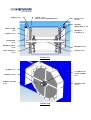
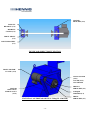
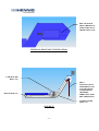
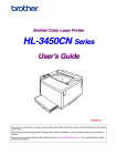
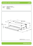
Chip Disc Filtration System
Service Manual
Hennig, Inc.
9900 N. Alpine Road
Machesney Park, Il 61115
(815)636-9900 (Ph.) (815)636-9737 (Fax)
E-Mail: [email protected]
Manual Revision Date: 1/15/09
HENNIG CHIP DISC FILTRATION SYSTEM
-1-
The Hennig Chip Disc Filtration System, or CDF System, is available in a variety of
configurations to be adaptable to a wide array of machine tool applications. The CDF System is
designed to remove chips and debris from coolant used in machine tool applications. The life of
the CDF System can be extended greatly by following the instructions and guidelines in this
manual. For assistance in new applications or questions regarding your system, please contact a
Customer Service Representative at our U.S. manufacturing facility:
Hennig, Inc.
9900 N. Alpine Road
Machesney Park, Il 61115
(815) 636-9900
(815) 636-9737 (fax)
Index
Introduction to Hennig CDF System ……………………………………………… Page 2
Ordering Instructions for Parts ……………………………………………………. Page 2
Installation and Start-up Instructions ……………………………………………… Page 3
Scheduled Maintenance Procedures …………...………………………………..… Page 4
Belt Removal, Maintenance, & Installation Procedure …………………………… Page 5 & 6
Parts List and Drawings ………………………………………………………….... Page 7 - 13
IIM
MPPO
OR
RTTA
AN
NTT IIN
NSSTTR
RU
UC
CTTIIO
ON
NSS F
FO
OR
R
O
OR
RD
DE
ER
RIIN
NG
G PPA
AR
RTTSS
It is important to have the following information available when ordering parts:
• Hennig CDF System Model Number*
• Hennig Serial Number*
• Part Name & Number (per parts list)
• Manual Revision Date (found on page 1)
(*) - May be found on the name plate located on the side of the head section of the conveyor.
-2-
INSTALLATION AND START-UP INSTRUCTIONS
Your new Hennig CDF System has been tested and inspected prior to delivery to ensure its
proper function upon installation. Please follow these instructions for start-up of your system:
1. Visually inspect your system for any shipping damage. Contact Hennig, Inc. immediately if
damage has occurred.
2. Roll entire system (filter/conveyor and tank) into position so that the filter/conveyor chip
chute is located under the machine coolant/chip discharge.
3. Level coolant tank using leveling screws mounted on the sides. After the tank is level, adjust
the support feet or casters (if supplied) of the filter/conveyor for sufficient support. Tighten
locknuts.
4. Install power and auxiliary control cables into electrical box or switch. Be sure to use the
correct voltage and phase for the system. Proper rotation of the filter/conveyor belt & pumps
may be obtained by reversing power connection. It is very important that all motors rotate in
the proper direction.
5. Make sure all foreign objects such as shipping papers, crating, cleaning rags, etc. are
removed from the filter/conveyor prior to start-up.
6. Check the belt tension of the conveyor. Adjust tension using tension bolts and lock in place
using jam nuts if required.
7. Install Disc(s) if shipped loose – Very important - Be sure to grease “v-seal” and/or
“wearplate” surface with standard bearing/axel grease. Slide “disk ass’y” onto disc
“shaft,” install “clamp nut” and tighten until “v-seal” is compressed to overall height
12.5/13.5 mm. Tighten “lock screw” on “clamp nut.” (Figure #3A, #3B, & #3C)
8. Fill the coolant tank to the level indicated on the CDF System layout drawing. Typically the
coolant level can be maintained approximately 2” below the covers of the tank. Check for
any leakage and contact Hennig, Inc. if any occurs. If an integral super-clean tank is
supplied, be sure to fill it with coolant also. Warning: Never fill a tank with the pumps
running (tank may overflow when coolant returns from machine due to over filling).
9. Install all required plumbing to pumps, chillers, bag filters, etc. Ensure that all fittings are
correctly tightened before starting pumps. Check for leaking fittings and tighten accordingly.
10. Install wiring for pumps, chillers, oil skimmers, hi/low float switches, etc. to machine
electrical system if required. Ensure that all electrical service meets local codes.
11. Make sure hands, feet, and clothing are clear of all moving parts before start-up.
12. Make sure all drive train guarding is in place and securely attached before start-up.
13. Locate a chip hopper under the filter/conveyor discharge for collection of chips.
14. Start-up machine and Hennig CDF System.
15. Set filter backwash flow rate using valve as shown in chart (Figure #1).
Note: The filter conveyor should be set up to run continuously while machine tool is discharging
coolant and chips. Unusually high amounts of chips during a short period of time can result in
jamming the filter/conveyor.
C
CA
AU
UT
TIIO
ON
N::
K
KE
EE
EPP H
HA
AN
ND
DSS,, F
FE
EE
ETT,, A
AN
ND
DC
CLLO
OTTH
HIIN
NG
GC
CLLE
EA
AR
R
O
OF
FM
MO
OV
VIIN
NG
G PPA
AR
RTTSS O
OF
FF
FIILLTTE
ER
R//C
CO
ON
NV
VE
EYYO
OR
R
-3-
SCHEDULED MAINTENANCE PROCEDURES
Daily Maintenance:
1. Check coolant level in tank. Fill if necessary. Never fill tank with pumps in operation –
overflow may occur due to overfilling once pumps are shut off.
2. Check filter “backwash system” for sufficient spray. Check “Y – Strainer” for chips and
clean out as required. (Figure #1)
3. Insert 1-3 shop rags down under the discharge of hinge belt filters/conveyors and allow them
to run through the conveyor in an effort to clean out any chips. Repeat if necessary.
Caution: Do not stick hands into harms way of conveyor belt – avoid pinch points.
4. Check the coolant discharge level of the “disc.” If the coolant level in the conveyor is higher
than normal, check the “filter screen” for abnormal blockage. If the “backwash system” is
operating properly, consideration should be given to steam cleaning or replacing the “filter
screen.”
1000 Hour Maintenance:
1. Check tension of filter/conveyor “hinge/scraper belt” by checking the torque setting of the
“adjusting screws” for the “take-up bearings” on each side of the head (Figure 4D). Torque
to be set at 25 in-lbs. Note: If the “hinge/scraper belt” tension is adjusted please check the
“motor drive chain” tension as it may have changed. (Figure #4C) Adjust “chain guard” as
required (Figure #4A).
2. The “torque limiter” (or clutch) is set at the factory. The torque setting can vary between
individual systems but typically ranges between 20 – 60 ft-lbs. Do not over-tighten the
“torque limiter” as damage may occur to the filter/conveyor in the event of a jam. (Figure
#4C)
3. Check the tension and alignment of the “motor drive chain.” There should be approximately
½” of slack (side to side) on the chain. The chain should also be lightly oiled at this time,
taking care not to introduce oil to the “torque limiter friction pads.” (Figure #4C)
4. Grease “take-up bearings” with grease gun. Do not over grease – seals can be damaged.
(Figure #4B & #4D)
5. Inspect “hinge/scraper belt” for wear or damage. (See Hinge/Scraper Belt Removal and
Installation Procedure if necessary)
6. Remove “disc assembly” and check seal and screen for damage. Replace or clean if
necessary. Upon re-installation, be sure to tighten “clampnut” until “v-seal” is compressed to
overall height of 12.5-13.5 mm. Lock “clampnut” in place by tightening “lock screw.”
(Figure #3A, #3B, & #3C)
7. Check “backwash system” for sufficient flow and pressure. Clean out any chips found in “Y
– Strainer” or “spray nozzles.” (Figure #1 & #3A)
8. Check “disc drive bearings” and lubricate with grease. Check “wear plate” for wear –
replace as necessary. (Figure #3A)
9. Maintain pumps, chillers, oil skimmers, etc. per manufacturer’s service manual.
10. For “Cast Iron Filter” option, check “scraper blade” for wear and adjust as necessary. Also,
check “idler chain” and “drum drive chain” for slack. Adjust tension with “adjusting screws”
grease “pillow block bearings” & “magnetic drum bearings” with grease gun. (Figure #8B)
-4-
BELT REMOVAL, MAINTENANCE, AND INSTALLATION
Hennig CDF Systems are typically equipped with either a “hinge belt” or “scraper belt”
dependant upon the specific application. The “scraper belt” is wide open for viewing of critical
components so maintenance requirements are easily seen. On the other hand, inspection of the
“hinge belt” can be slightly more involved. General inspection of either belt type can be
accomplished at the discharge opening at the head of the filter/conveyor, by removal of the slide
lid, or through openings in the trough (Figure #2). Detailed inspection of a “hinge belt,”
however, requires complete removal of the belt from the filter/conveyor body to provide
complete access to all the integrated components.
“Hinge Belt” Removal:
1. Disconnect power source to filter/conveyor.
2. Drain tank or remove filter/conveyor from tank as required.
3. Run filter/conveyor until the “master shaft” (identified as shaft with cotter pins and washers)
are positioned at the slot opening located near the discharge of the conveyor (so that the
“master shaft” may be knocked out – Figure #6). Note: if the filter/conveyor is jammed and
cannot be run, go to step #4.
4. Remove “flip lid,” “bearing cover,” “outside chain guard,” and “slot guards” (found at
discharge end of conveyor – Figure #2).
5. Remove “drive chain” from the “gear motor” by reducing tension and removing “chain
master link.” (Figure #5) For optional direct drive motor mounting, remove motor mounting
screws and nuts and pull motor off drive shaft. (Figure #4A)
6. Turn “take-up bearing screws” counter-clockwise to reduce tension of “hinge belt.” Be sure
to note the position of the bearings prior to reducing tension so the correct tension may be
easily set upon re-installation. (Figure #4D)
7. Remove “cotter pin” and “washer” from “master shaft.” Slide the “master shaft” out of the
belt assembly. If the “master shaft” cannot be moved into removal position (as stated in step
#3), any “shaft” located in the slot near the discharge of the filter/conveyor may be removed
by, first, grinding the crimp from the end of the “shaft” to allow for removal (a new “master
shaft” may be obtained from Hennig, Inc.). (Figure #5)
8. At this point, the belt should easily be disconnected. Re-install the “master shaft” into the
belt in the top section only to aid in belt removal.
9. Remove “disc cover” and loosen the “clampnut” & “lock screw” enough to relieve the
friction of the “seal” with the “wear plate.” (Figure #3A & #3B)
10. Remove the belt assembly from the filter/conveyor by pulling out the bottom end of the belt
assembly first (the “master shaft” should trail the belt assembly as it comes out). (Figure #7)
C
CA
AU
UT
TIIO
ON
N::
A
ALLW
WA
AYYSS D
DIISSC
CO
ON
NN
NE
EC
CTT PPO
OW
WE
ER
RB
BE
EF
FO
OR
RE
E
PPE
R
F
O
R
M
I
N
G
A
N
Y
M
A
I
N
T
E
N
A
N
C
E
ERFORMING ANY MAINTENANCE
-5-
“Hinge Belt” Maintenance:
1. Clean belt – remove excessive build up of chips and swarf.
2. Visually inspect belt for damage and wear.
a. Ensure that rollers are rotating freely and check for wear. (Figure #5)
b. Check belt shafts for wear. (Figure #5)
c. Ensure that stainless steel scrapers &/or polyurethane wipers (mounted to cleats on hinge
belt) are not worn or damaged – replace if necessary.
d. Check “hinge plates” for damage. (Figure #5)
3. Check guide rails, sprockets, rail knobs, and conveyor body for wear or damage. (Figure #7)
C
CA
AU
UT
TIIO
ON
N::
A
ALLW
WA
AYYSS W
WE
EA
AR
R PPR
RO
OTTE
EC
CTTIIV
VE
EG
GLLO
OV
VE
ESS W
WH
HE
EN
N
H
HA
AN
ND
DLLIIN
NG
GA
AH
HIIN
NG
GE
EB
BE
ELLTT
“Hinge Belt” Installation:
1. With “master shaft” installed as stated in the “Hinge Belt Removal” procedure (step #8), feed
the belt in (master shaft first) on lower rail system until the ends of the belt meet back up at
the discharge of the filter/conveyor. (Figure #7)
2. Remove the “master shaft” and mesh the two knuckles of the mating hinge plates together.
Slide the master shaft through the mating parts of the belt assembly (install “washers” and
“cotter pin” on each end). (Figure #5)
3. Adjust the belt tension by checking the torque setting of the “adjusting screws” for the “takeup bearings” on each side of the head. Torque to be set at 25 in-lbs or adjust “take-up
bearings” to original position. (Figure #4D)
4. For overhead drives, install “motor drive chain” and tension until there is ½” of play side to
side (Figure #4C). For direct drive motor option, install gearmotor by sliding over shaft and
key, and replace motor mounting screws and nuts. (Figure #9)
5. Tighten “clampnut” until filter disc seal is compressed to overall height of 12.5 to 13.5 mm
overall height. Lock “clampnut” in place with “lock screw” and replace “disc cover.”
(Figure #3A & #3B)
6. Replace all guards and covers.
7. Re-install filter/conveyor into tank and add coolant as required.
8. Connect power source.
SSP
PA
AR
RE
EB
BE
EL
LT
TP
PA
AR
RT
TSS A
AN
ND
D
C
CO
OM
MP
PL
LE
ET
TE
EB
BE
EL
LT
TA
ASSSSE
EM
MB
BL
LIIE
ESS C
CA
AN
N
B
BE
EP
PU
UR
RC
CH
HA
ASSE
ED
DA
AT
TH
HE
EN
NN
NIIG
G,, IIN
NC
C..
-6-
PARTS LISTS
HOSE (1-1)
VALVE (1-2)
BACKWASH
PUMP (1-4)
FIGURE #1
Y-STRAINER
(1-3)
SLIDE LID
(2-1)
FLIP LID (2-4)
FILTER
HOUSING
COVER (2-6)
HEAD (2-5)
TROUGH
(2-3)
FILTER
ASS’Y (2-2)
FIGURE #2
-7-
SCREW (3-1)
V-SEAL (3-14)
(12.5/13.5 mm COMPRESSION)
Bearing/Axel
Grease
FILTER
SPROCKET (3-15)
DISC COVER
(3-2)
BEARING
COVER (3-7)
NOZZLE (3-5)
MANIFOLD
(3-4)
BEARING SEAT
(3-16)
BEARING (3-9)
DISC CASTING
(3-13)
SHAFT (3-12)
FIGURE #3A
SCREW (3-3)
CLAMPNUT &
LOCK SCREW
(3-6)
SCREEN (3-10)
SCREEN CLAMP
(3-11)
WEARPLATE
(3-15)
FIGURE #3B
-8-
SCREEN (3-10)
DISC CASTING
(3-13)
SCREEN CLAMP
(3-11)
V-SEAL (3-14)
FIGURE #3C (DISK ASS’Y)
DRIVE MOTOR DIRECT DRIVE
(4-9)
CHAIN GUARD
(4-8)
FIGURE #4A (DIRECT DRIVE – FLIP LID NOT SHOWN)
-9-
MOTOR
BRACKET (4-8)
TAKE-UP
BEARING (4-6)
BEARING
COVER (4-5)
DRIVE SHAFT
(4-2)
BELT SPROCKET
(4-1)
FIGURE #4B (DIRECT DRIVE SECTION)
DRIVE MOTOR IN LINE (4-11)
CHAIN GUARD
(4-10)
COVER (4-15)
NOT SHOWN
DRIVEN
SPROCKET (4-3)
MOTOR
ADJUSTING
SCREW & NUT
(4-14)
TORQUE
LIMITER (4-4)
FIGURE #4C (OVERHEAD DRIVE W/ TORQUE LIMITER)
- 10 -
DRIVE
SPROCKET (4-7)
BEARING
BRACKET (4-12)
TAKE-UP
BEARING (4-6)
JAM NUT (4-13)
ADJUSTING
SCREW (4-9)
FIGURE #4D (BEARING COVER REMOVED)
CLEAT (5-1)
HINGE PLATE (5-2)
SIDEWING (5-3)
SHAFT (5-4)
CHAIN SIDE LINK
(5-5)
CHAIN ROLLER
LINK (5-6)
WASHER (5-7)
COTTER PIN (5-8)
MASTER SHAFT
(5-9)
FIGURE #5 (HINGE BELT ASS’Y.)
- 11 -
BELT MASTER
SHAFT REMOVAL
THRU THIS SLOT
(REMOVE PLATE)
FIGURE #6 (HINGE BELT FILTER HEAD)
UPPER GUIDE
RAIL (7-2)
BELT
INSTALLATION:
FEED BELT INTO
CONVEYOR ON
LOWER RAILS
(REVERSE
DIRECTION FOR
BELT REMOVAL)
RAIL KNOB (7-3)
LOWER GUIDE
RAIL (7-1)
FIGURE #7
- 12 -
CAST IRON
FILTER
HOUSING (7-1)
FIGURE #8A (CAST IRON OPTION)
ADJUSTING
SCREW & NUT
(7-11)
DRUM DRIVE
CHAIN
(7-6)
MAGNETIC DRUM
(BEARINGS NOT
SHOWN) (7-3)
DRUM DRIVE
SPROCKET
(7-4)
ADJUSTABLE
SCRAPER BLADE
(7-12)
DRUM DRIVE
SHAFT
(7-5)
SCRAPER BLADE
BRACKET
(7-13)
BEARING
(7-7)
IDLER SHAFT
(7-8)
FILTER DRIVE
SPROCKET
(7-2)
IDLER SPROCKET
(7-9)
IDLER CHAIN
(7-10)
FIGURE #7B (CAST IRON OPTION)
- 13 -