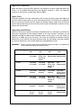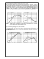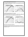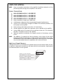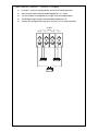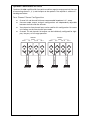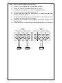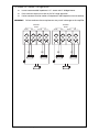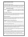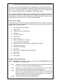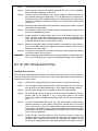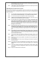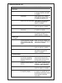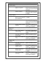
1
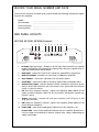
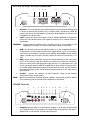
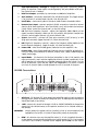
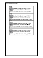
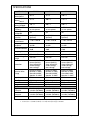
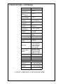
Warranty
LIMITED TWO YEAR CONSUMER WARRANTY:
Directed Electronics promises to the original purchaser, to replace this product should it prove to
be defective in workmanship or material under normal use, for a period of two years from the date
of purchase by the dealer as indicated by the date code marking of the product PROVIDED the
product was installed by an authorized Directed dealer. During this two year period, there will be
no charge for this replacement PROVIDED the unit is returned to Directed, shipping pre-paid. If
the unit is installed by anyone other than an authorized Directed dealer, the warranty period will
be 1 year from date of purchase by the dealer as indicated by the date code marking of the
product. During this 1 year period, there will be no charge for this replacement PROVIDED the
unit is returned to Directed, shipping pre-paid. This warranty is non-transferable and does not
apply to any unit that has been modified or used in a manner contrary to its intended purpose,
and does not cover damage to the unit caused by installation or removal of the unit. This warranty
is void if the product has been damaged by accident or unreasonable use, neglect, improper service
or other causes not arising out of defects in materials or construction. ALL WARRANTIES
INCLUDING BUT NOT LIMITED TO EXPRESS WARRANTY, IMPLIED WARRANTY, WARRANTY
OF MERCHANTABILITY, FITNESS FOR PARTICULAR PURPOSE, AND WARRANTY OF NONINFRINGEMENT OF INTELLECTUAL PROPERTY ARE EXPRESSLY EXCLUDED TO THE
MAXIMUM EXTENT ALLOWED BY LAW, AND DIRECTED NEITHER ASSUMES NOR
AUTHORIZES ANY PERSON TO ASSUME FOR IT ANY LIABILITY IN CONNECTION WITH THE
SALE OF THE PRODUCT. DIRECTED HAS ABSOLUTELY NO LIABILITY FOR ANY AND ALL ACTS
OF THIRD PARTIES INCLUDING ITS AUTHORIZED DEALERS OR INSTALLERS. Unit must be
returned to Directed, postage pre-paid, with: consumer's name, telephone number, and address,
authorized dealer's name and address, and product description. IN ORDER FOR THIS WARRANTY
TO BE VALID, YOUR UNIT MUST BE SHIPPED WITH PROOF OF INSTALLATION BY AN
AUTHORIZED DIRECTED DEALER. ALL UNITS RECEIVED BY DIRECTED FOR WARRANTY
REPAIR WITHOUT PROOF OF DIRECTED DEALER INSTALLATION WILL BE COVERED BY THE
LIMITED 1 YEAR PARTS AND LABOR WARRANTY. Note: This warranty does not cover labor costs
for the removal and reinstallation of the unit.
BY PURCHASING THIS PRODUCT, THE CONSUMER AGREES AND CONSENTS THAT ALL
DISPUTES BETWEEN THE CONSUMER AND DIRECTED SHALL BE RESOLVED IN ACCORDANCE
WITH CALIFORNIA LAWS IN SAN DIEGO COUNTY, CALIFORNIA.
© 2006 Directed Electronics, All rights reserved. G47520.25.30.40 05-06
HP-2300
HP-2400
HP-2600
HP-4600
CONTENTS
Introduction . . . . . . . . . . . . . . . . . . . . . . . . . . . . . . . . . . . . . . . . . . . . . . . . . . . . . . . . . . . . . . . .2
What’s in the Box . . . . . . . . . . . . . . . . . . . . . . . . . . . . . . . . . . . . . . . . . . . . . . . . . . . . . . .2
Practice Safe Sound™ . . . . . . . . . . . . . . . . . . . . . . . . . . . . . . . . . . . . . . . . . . . . . . . . . . . . . . . .2
Record Your Serial Number and Date . . . . . . . . . . . . . . . . . . . . . . . . . . . . . . . . . . . . . . . . . . .3
End Panel Layouts . . . . . . . . . . . . . . . . . . . . . . . . . . . . . . . . . . . . . . . . . . . . . . . . . . . . . . . . . . .3
HP-2300, HP-2400, HP-2600 Controls . . . . . . . . . . . . . . . . . . . . . . . . . . . . . . . . . . . . . . . .3
HP-2300, HP-2400, HP-2600 Connections . . . . . . . . . . . . . . . . . . . . . . . . . . . . . . . . . . . . .4
HP4600 Controls . . . . . . . . . . . . . . . . . . . . . . . . . . . . . . . . . . . . . . . . . . . . . . . . . . . . . . . .4
HP4600 Connections . . . . . . . . . . . . . . . . . . . . . . . . . . . . . . . . . . . . . . . . . . . . . . . . . . . . .5
CEA Specifications . . . . . . . . . . . . . . . . . . . . . . . . . . . . . . . . . . . . . . . . . . . . . . . . . . . . . . . . . . .7
specifications . . . . . . . . . . . . . . . . . . . . . . . . . . . . . . . . . . . . . . . . . . . . . . . . . . . . . . . . . . . . . . .8
specifications—Continued . . . . . . . . . . . . . . . . . . . . . . . . . . . . . . . . . . . . . . . . . . . . . . . . . . . . .9
Amplifier Settings . . . . . . . . . . . . . . . . . . . . . . . . . . . . . . . . . . . . . . . . . . . . . . . . . . . . . . . . . .10
Signal Input and Output Configurations . . . . . . . . . . . . . . . . . . . . . . . . . . . . . . . . . . . .10
Input Gain . . . . . . . . . . . . . . . . . . . . . . . . . . . . . . . . . . . . . . . . . . . . . . . . . . . . . . . . . . . .10
Line Output Configurations . . . . . . . . . . . . . . . . . . . . . . . . . . . . . . . . . . . . . . . . . . . . . .10
Low-Pass Crossover . . . . . . . . . . . . . . . . . . . . . . . . . . . . . . . . . . . . . . . . . . . . . . . . . . . . .10
High-Pass Crossover . . . . . . . . . . . . . . . . . . . . . . . . . . . . . . . . . . . . . . . . . . . . . . . . . . . . .11
Adjusting Intelli-Bass . . . . . . . . . . . . . . . . . . . . . . . . . . . . . . . . . . . . . . . . . . . . . . . . . . . .11
Infinite Baffle Example High-Pass Set at 30Hz . . . . . . . . . . . . . . . . . . . . . . . . . . . . . . .12
Sealed Example High-Pass Set at 20Hz . . . . . . . . . . . . . . . . . . . . . . . . . . . . . . . . . . . . .12
Sealed Example High-Pass Set at 30Hz . . . . . . . . . . . . . . . . . . . . . . . . . . . . . . . . . . . . .13
Vented Example High-Pass Set at 30Hz . . . . . . . . . . . . . . . . . . . . . . . . . . . . . . . . . . . . .13
Remote Bass Operation (optional) . . . . . . . . . . . . . . . . . . . . . . . . . . . . . . . . . . . . . . . . .13
Amplifier Wiring . . . . . . . . . . . . . . . . . . . . . . . . . . . . . . . . . . . . . . . . . . . . . . . . . . . . . . . . . . .14
Power Connections . . . . . . . . . . . . . . . . . . . . . . . . . . . . . . . . . . . . . . . . . . . . . . . . . . . . .14
High Level Input Harness . . . . . . . . . . . . . . . . . . . . . . . . . . . . . . . . . . . . . . . . . . . . . . . .14
Speaker Connections HP-2300, HP-2400, and HP-2600 . . . . . . . . . . . . . . . . . . . . . . . . .15
Speaker Connections HP-4600 . . . . . . . . . . . . . . . . . . . . . . . . . . . . . . . . . . . . . . . . . . . .17
Amplifier Installation . . . . . . . . . . . . . . . . . . . . . . . . . . . . . . . . . . . . . . . . . . . . . . . . . . . . . . .20
Choosing Mounting Locations . . . . . . . . . . . . . . . . . . . . . . . . . . . . . . . . . . . . . . . . . . . .20
Passenger Compartment . . . . . . . . . . . . . . . . . . . . . . . . . . . . . . . . . . . . . . . . . . . . . . . . .20
Trunk Compartment . . . . . . . . . . . . . . . . . . . . . . . . . . . . . . . . . . . . . . . . . . . . . . . . . . . .20
General Precautions and Installation Tips . . . . . . . . . . . . . . . . . . . . . . . . . . . . . . . . . . .20
Tools of the Trade . . . . . . . . . . . . . . . . . . . . . . . . . . . . . . . . . . . . . . . . . . . . . . . . . . . . . .21
Step By Step Installation . . . . . . . . . . . . . . . . . . . . . . . . . . . . . . . . . . . . . . . . . . . . . . . . .21
Set Up and Troubleshooting . . . . . . . . . . . . . . . . . . . . . . . . . . . . . . . . . . . . . . . . . . . . . . . . . .22
Testing the System . . . . . . . . . . . . . . . . . . . . . . . . . . . . . . . . . . . . . . . . . . . . . . . . . . . . . .22
Adjusting the Sound of the System . . . . . . . . . . . . . . . . . . . . . . . . . . . . . . . . . . . . . . . .23
Troubleshooting Tips . . . . . . . . . . . . . . . . . . . . . . . . . . . . . . . . . . . . . . . . . . . . . . . . . . . .24
© 2006 Directed Electronics, all rights reserved
1
INTRODUCTION
Thank you for your purchase of Orion's amplifier. Each Orion amplifier is designed to be the
leader in its class offering ease of use, advanced features, and the most power. Orion amplifiers are designed as the best affordable high end car audio amplifier money can buy. Listed
below are the features of these new Orion amplifiers.
●
HP-2300 - 50 Watts per channel, two-channel amplifier with dual built-in highpass and low-pass 12dB/octave crossover centered at 100Hz and Intelli-Bass. The
HP-2300 is capable of 3, 2, or 1 channel operation with a maximum power of 150
Watts into 4W mono.
●
HP-2400 - 75 Watts per channel, two-channel amplifier with dual built-in highpass and low-pass 12dB/octave crossover centered at 100Hz and Intelli-Bass. The
HP-2400 is capable of 3, 2, or 1 channel operation with a maximum power of 200
Watts into 4W mono.
●
HP-2600 - 100 Watts per channel, two-channel amplifier with dual built-in highpass and low-pass 12dB/octave crossover centered at 100Hz and Intelli-Bass. The
HP-2400 is capable of 3, 2, or 1 channel operation with a maximum power of 300
Watts into 4W mono.
●
HP-4600 - 50 Watts per channel, four-channel amplifier with dual built-in highpass and low-pass 12dB/octave crossover centered at 100Hz and Intelli-Bass. The
HP-4600 is capable of 6, 5, 4, 3, or 2 channel operation with a maximum power
capability of 300 Watts into 4W stereo (channels 1/2 and 3/4 bridged.)
The installation of all Orion amplifiers will determine the overall performance result.
Improper installation will not only limit the performance of your Orion system but also
potentially compromise the reliability of the amplifier. To ensure proper sonic results and
component reliability, please refer to your Authorized Orion dealer for installation assistance or advice. If you decide to perform the installation yourself, read the entire manual
before beginning the installation.
What’s in the Box
●
(1) amplifier
●
(1) spare fuse(s)
●
(1) Allen wrench 4mm
●
(1) Allen wrench 3mm
●
(1) hardware kit
●
(1) Amplifier installation and operation manual
●
(1) Window decal
PRACTICE SAFE SOUND™
Continuous exposure to sound pressure levels over 100dB may cause permanent hearing
loss. High power automotive sound systems can generate sound pressure levels in excess of
130dB. When playing your system at high levels, please use hearing protection and avoid
long term exposure.
2
© 2006 Directed Electronics, all rights reserved
RECORD YOUR SERIAL NUMBER AND DATE
To ensure your warranty (see back cover), please record the following information regarding your new amplifier.
Model:
__________________________________________________
Serial Number:
__________________________________________________
Date of Purchase: __________________________________________________
Purchased from:
__________________________________________________
END PANEL LAYOUTS
HP-2300, HP-2400, HP-2600 Controls
1
2
3
HI INPUT
INPUT
LINE OUT
L CH
L CH
4
5
6
7
8
9
X-OVER
HPF
10
POWER
(GREEN)
GAIN
INTELLI-BASE REMOTE
LPF
PROTECT
(RED)
LPF
MIN
R CH
MAX
0dB
12dB
50Hz
500Hz
FLAT
HPF
50Hz
500Hz
R CH
1.
Hi Input (high level input) - Accepts 1V to 10V input from the head unit’s speaker
output. The amplifier will automatically wake-up when the input is greater than 1V.
High level input harness shown below.
2.
RCA Input - accepts RCA input from a head unit, preamplifier, or equalizer.
3.
RCA Line Output - provides easy connection to additional amplifiers.
4.
Gain Control - continuous adjustment for full power output.
5.
Intelli-Bass - continuously adjusts from 0 to 12dB of boost centered at 45Hz.
6.
Remote Bass Input - connects optional HP-RB1 remote bass control to control
the bass level from the driver’s seat. This control is only active when the crossover
switch is at the LPF setting.
7.
LPF (Low-Pass Frequency Control) - adjusts the frequency (50Hz–500Hz) of the
upper crossover frequency. When set for this position the optional remote bass
control is active.
8.
X-Over (cross-over) - activates LPF (low pass crossover), FLAT (all pass), or HPF
(high pass crossover).
9.
HPF (High-Pass Frequency Control) - adjusts the frequency (50Hz–500Hz) of the
lower crossover frequency.
10. Power LED - when illuminated (green) indicates that the amplifier is on.
Protect LED - when illuminated (red) indicates that the amplifier protective circuitry has been activated due to thermal, output short, supply undervoltage or
supply overvoltage.
© 2006 Directed Electronics, all rights reserved
3
HP-2300, HP-2400, HP-2600 Connections
1
2
3
4
REM
GND
5
SPEAKER
FUSE
+BAT
L CH
+
BRIDGE
R CH
-
L CH
+
R CH
-
1.
ATC Fuse - ATC fuses protect the amplifier against internal electrical damage and
is meant to protect the amplifier only. All other power connections should be
fused at the source. The HP-2300 has (1) 20-amp, the HP-2400 has (1) 30-amp, the
HP-2600 has (2) 20-amp fuses.
2.
+BAT - connect this terminal through a FUSE or CIRCUIT BREAKER to the positive
terminal of the vehicle battery or the positive terminal of an isolated audio system battery.
WARNING:
Always protect this power wire by installing a fuse or circuit breaker of the
appropriate size within 12 inches of the battery terminal connection.
3.
REM - this terminal turns on the amplifier when (+) 12 volt is applied. Connect it
to the remote turn on lead of the head unit or signal source. If a (+) 12 volt remote
turn lead is not available, a Remote Power Adapter (P/N #55000) can be used to
supply a remote turn on signal. DO NOT connect this terminal to constant (+) 12
volt.
4.
GND - power return connection. Connect this terminal directly to the sheet metal
chassis of the vehicle, using the shortest wire necessary to make this connection.
Always use wire of the same gauge or larger than the (+) 12 volt power wire. The
chassis connection point should be scraped free of paint and dirt. Use only quality crimped and/or soldered connectors at both ends of this wire. DO NOT connect
this terminal directly to the vehicle battery ground terminal or any other factory
ground points.
5.
Speaker - connect the speakers to these terminals. (refer to the Speaker
Connection section of this guide.)
NOTE:
Make all connections to power, ground, speakers, and remote terminals before
final positioning and installation of the amplifier in the vehicle.
HP4600 Controls
1
2
HI INPUT
1/2 CH
3
INPUT
1 CH
4
5
6
7
8
9
X-OVER
HPF
L CH
11
POWER
(GREEN)
LINE OUT
3 CH
10
GAIN INTELLIBASS REMOTE
LPF
PROTECT
(YELLOW)
LPF
HI INPUT
MIN
MAX
0dB
12dB
50Hz
500Hz
MIN
MAX
0dB
12dB
50Hz
500Hz
FLAT
HPF
X-OVER
50Hz
500Hz
50Hz
500Hz
3/4 CH
LPF
LPF
2 CH
1.
4
4 CH
R CH
FLAT
HPF
HPF
INPUT
MODE
1/2 CH
3/4 CH
GAIN INTELLIBASS
Hi Input (high level input Ch 1/2 and Ch 3/4) - Accepts 1v to 10v input from the head
unit’s speaker output. The amplifier will automatically wake-up when the input is
greater than 1V (on channel 1/2 high level input only).
© 2006 Directed Electronics, all rights reserved
2.
RCA Input Channels 1 through 4 - accepts RCA input from a head unit, preamplifier, or equalizer. These inputs are configured by the Input Mode switch position (refer to item 11 below).
3.
RCA Line Output - provides easy connection to additional amplifiers.
4.
Gain Control - continuous adjustment for full power output. The upper control
is for channels 1/2 and the lower control is for channels 3/4.
5.
Intelli-Bass - continuously adjusts from 0 to 12dB of boost centered at 45Hz.
6.
Remote Bass Input - connects optional HP-RB1 remote bass control to control
the bass level from the driver’s seat. The HP-RB1 is only active when the crossover
switch (lower switch) for channels 3/4 is at the LPF setting.
7.
LPF (Low-Pass Frequency Control) - adjusts the frequency (50Hz–500Hz) of the
upper crossover frequency. When set for this position the optional remote bass
control is active (upper channels 1/2, lower channels 3/4).
8.
X-Over (cross-over) - activates LPF (low pass crossover), FLAT (all pass), or HPF
(high pass crossover) (upper channels 1/2, lower channels 3/4).
9.
HPF (High-Pass Frequency Control) - adjusts the frequency (50Hz–500Hz) of the
lower crossover frequency (upper channels 1/2, lower channels 3/4).
10. Power LED - when illuminated (green) indicates that the amplifier is on.
Protect LED - when illuminated (red) indicates that the amplifier protective circuitry has been activated due to thermal, output short, supply undervoltage or
supply overvoltage.
11. Input Mode - 1/2 channel or 3/4 channel selectable. In the 1/2 CH position, the
input to channels 1 and 2 are also supplied to channels 3 and 4, respectively. In the
3/4 CH position all 4 channels are supplied separately When the switch is to the
left (4 CH position), front and rear inputs are independent. This allows a source
unit with an internal fader to fade between the 1/2 CH and 3/4 CH outputs.
HP4600 Connections
1
2
3
4
FUSE
+BAT
REM
GND
5
6
SPEAKER
1CH
+
1CH
BRIDGE
2CH
-
SPEAKER
+
2CH
-
3CH
+
3CH
BRIDGE
4CH
-
+
4CH
-
1.
ATC Fuse - (2) 20-amp ATC fuses protect the amplifier against internal electrical
damage and is meant to protect the amplifier only. All other power connections
should be fused at the source.
2.
+BAT - connect this terminal through a FUSE or CIRCUIT BREAKER to the positive
terminal of the vehicle battery or the positive terminal of an isolated audio system battery.
WARNING:
3.
Always protect this power wire by installing a fuse or circuit breaker of the
appropriate size within 12 inches of the battery terminal connection.
REM - this terminal turns on the amplifier when (+) 12 volt is applied. Connect it
to the remote turn on lead of the head unit or signal source. If a (+) 12 volt remote
turn lead is not available, a Remote Power Adapter (P/N #55000) can be used to
© 2006 Directed Electronics, all rights reserved
5
supply a remote turn on signal. DO NOT connect this terminal to constant (+) 12
volt.
4.
GND - power return connection. Connect this terminal directly to the sheet metal
chassis of the vehicle, using the shortest wire necessary to make this connection.
Always use wire of the same gauge or larger than the (+) 12 volt power wire. The
chassis connection point should be scraped free of paint and dirt. Use only quality crimped and/or soldered connectors at both ends of this wire. DO NOT connect
this terminal directly to the vehicle battery ground terminal or any other factory
ground points.
5, 6. Speaker - connect the speakers to these terminals. (refer to the Speaker
Connection section of this guide.)
NOTE:
6
Make all connections to power, ground, speakers, and remote terminals before
final positioning and installation of the amplifier in the vehicle.
© 2006 Directed Electronics, all rights reserved
CEA SPECIFICATIONS
HP-2300
Power Output: 50 Watts RMS x 2 at 4 ohms and < 1% THD+N
Signal to Noise Ratio: -70 dBA (reference 1 Watt into 4 ohms)
Additional Power Output: 75 Watts RMS x 2 at 2 ohm at 14.4 Supply<1% THD+N
HP-2400
Power Output: 75 Watts RMS x 2 at 4 ohms and < 1% THD+N
Signal to Noise Ratio: -75 dBA (reference 1 Watt into 4 ohms)
Additional Power Output: 100 Watts RMS x 2 at 2 ohm at 14.4 Supply<1% THD+N
HP-2600
Power Output: 100 Watts RMS x 2 at 4 ohms and < 1% THD+N
Signal to Noise Ratio: -75 dBA (reference 1 Watt into 4 ohms)
Additional Power Output: 175 Watts RMS x 2 at 2 ohm at 14.4 Supply<1% THD+N
HP-4600
Power Output: 50 Watts RMS x 4 at 4 ohms and < 1% THD+N
Signal to Noise Ratio: -80 dBA (reference 1 Watt into 4 ohms)
Additional Power Output: 75 Watts RMS x 4 at 2 ohm at 14.4 Supply<1% THD+N
© 2006 Directed Electronics, all rights reserved
7
SPECIFICATIONS
Amplifier Section
Power Output 4W
(Watts)note 1
Power Output 2W
(Watts)note 2
HP-2300
HP-2400
HP-2600
50 x 2
75 x 2
100 x 2
75 x 2
100 x 2
175 x 2
150 x 1
200 x 1
350 x 1
> 55% into 2W load
at max. power
> 55% into 2W load
at max. power
> 55% into 2W load
at max. power
yes
yes
yes
yes (HP-RB1
optional)
yes (HP-RB1
optional)
yes (HP-RB1
optional)
< 1.0% THD+N
< 1.0% THD+N
< 1.0% THD+N
20Hz to 20kHz
±0.5dB
10Hz to 50kHz
±3dB
> 200
150mV to 5V rms
20Hz to 20kHz
±2.5dB
10Hz to 50kHz
±3dB
> 200
150mV to 5V rms
20Hz to 20kHz
±2.5dB
10Hz to 50kHz
±3dB
> 200
150mV to 5V rms
9 to 18V
9 to 18V
9 to 18V
Protection
thermal, DC offset,
reverse polarity,
short protection,
under-voltage,
over-voltage
thermal, DC offset,
reverse polarity,
short protection,
under-voltage,
over-voltage
thermal, DC offset,
reverse polarity,
short protection,
under-voltage,
over-voltage
Terminal Wire
Gauge
Power 0/1 AWG,
Remote 12 AWG,
Ground 0/1AWG,
Speaker 12 AWG
Power 0/1 AWG,
Remote 12 AWG,
Ground 0/1AWG,
Speaker 12 AWG
Power 0/1 AWG,
Remote 12 AWG,
Ground 0/1AWG,
Speaker 12 AWG
Power Output 4W
(Watts) Bridged
Amplifier
Efficiency
Externally
Bridgeable
Remote Bass
Function
Distortion at
Rated Power
Frequency
Response
Linear Bandwidth
Damping Factor
Input Sensitivity
Supply Voltage
Range
Input Impedance
Fuse Type
Dimensions
Weight
High Pass
Crossover
Low Pass
Crossover
Intelli-Bass
20kW
20kW
(1) 20 Amp
(1) 30 Amp
7.5"x10.25 x 2.4"
7.5"x10.25 x 2.4"
5.0 lbs.
5.0 lbs.
Crossover Section
Continuously
Continuously
variable (50-500Hz)
variable (50-500Hz)
Continuously
Continuously
variable (50-500Hz)
variable (50-500Hz)
yes
yes
20kW
(2) 20 Amp
10.5"x10.25 x 2.4"
7.6 lbs.
Continuously
variable (50-500Hz)
Continuously
variable (50-500Hz)
yes
1. Continuous 4W load 20Hz to 20kHz, < 1% THD, with input voltage at 14.4VDC.
2. Continuous 2W load 20Hz to 20kHz, < 1% THD, with input voltage at 14.4VDC.
8
© 2006 Directed Electronics, all rights reserved
SPECIFICATIONS—CONTINUED
Amplifier Section
Power Output 4W
(Watts)note 1
Power Output 2W
(Watts)note 2
Power Output 4W
(Watts) Bridged
Amplifier
Efficiency
Externally
Bridgeable
Remote Bass
Function
Distortion at
Rated Power
Frequency
Response
Linear Bandwidth
Damping Factor
Input Sensitivity
Supply Voltage
Range
HP-4600
50 x 4
75 x 4
150 x 2
> 50% into 2W load
at max. power
yes
yes (HP-RB1
optional)
< 1.0% THD+N
20Hz to 20kHz
±0.25dB
10Hz to 50kHz
±3dB
> 300
250mV to 5V rms
9 to 18V
Protection
thermal, DC offset,
reverse polarity,
short protection,
under-voltage,
over-voltage
Terminal Wire
Gauge
Power 0/1 AWG,
Remote 12 AWG,
Ground 0/1AWG,
Speaker 12 AWG
20kW
Input Impedance
Fuse Type
(2) 20 Amp
Dimensions
10.5"x10.25” x 2.4"
Weight
7.6 lbs.
Crossover Section
High Pass
Continuously
Crossover
variable (50-500Hz)
Low Pass
Continuously
Crossover
variable (50-500Hz)
Intelli-Bass
yes
1. Continuous 4W load 20Hz to 20kHz, < 1% THD, with input voltage at 14.4VDC.
2. Continuous 2W load 20Hz to 20kHz, < 1% THD, with input voltage at 14.4VDC.
© 2006 Directed Electronics, all rights reserved
9
AMPLIFIER SETTINGS
Signal Input and Output Configurations
Depending on your model, the input section of the amplifier consists of gain controls, high
pass and low pass crossovers controls, Intelli-Bass control and RCA inputs and outputs. The
input section makes it easy to adapt this amplifier to most system configurations.
Input Gain
These Orion amplifiers have level adjustments to allow for easy integration with any source
unit. The input sensitivity can be adjusted from 150mV to 5V. Refer to Testing the System
and Adjusting the Sound of the System sections of this guide for detailed instructions on
setting the gain.
Line Output Configurations
The line outputs on Orion amplifiers offer easy system expansion. Routing signal from the
RCA line outputs to the next Orion amplifier’s RCA line inputs in the signal chain.
Internal Crossover Configurations
The crossover section of HP2300, HP2400 and HP2600 amplifiers are continuously variable
and extremely flexible. There are eight different crossover configurations possible allowing
high-pass, low-pass, and band-pass operation. This circuit is designed to optimize the performance of subwoofers in all types of enclosures.
When using Orion loudspeakers, minor deviations from the recommended frequency
ranges can provide superior results depending on your speaker locations and your vehicle
acoustics. Setting crossover frequencies higher than recommended will not cause damage
and may provide superior sonic results depending on your system's performance goals.
Refer to your loudspeaker owner's manual for assistance in choosing the proper crossover
frequencies for your system.
WARNING!
DO NOT set crossover frequencies lower than the speakers recommended
operating range. This can cause driver failure that is not covered by manufacturer's warranty.
Crossover Switch
Controls the type of filter for the onboard active crossover. The HP-4800 has two switches,
the upper switch is for channels 1/2, the lower switch is for channels 3/4.
Full position does not attenuate any frequencies and is for full range speaker systems.
High attenuates low frequencies and is used for mid-range speakers and tweeters.
Low attenuates high frequencies and is used for subwoofer speakers.
Low-Pass Crossover
When the switch is to the left (FULL position), the low-pass crossover is bypassed. When the
switch is to the right (LOW position), the low-pass crossover is active. The low-pass crossover
is continuously variable from 50Hz to 500Hz.
10
© 2006 Directed Electronics, all rights reserved
High-Pass Crossover
When the switch is to the left (FULL position), the high-pass crossover is bypassed. When the
switch is in the middle (HIGH position), the high-pass crossover is active. The high-pass
crossover is continuously variable from 50Hz to 500Hz.
Input Gain
The Orion amplifiers have gain adjustments with an input sensitivity range from 200mV up
to 5V on the RCA inputs and 1V to 10 on the high-level inputs. This allows easy integration
from any source unit either with RCA outputs or speaker outputs. Refer to the Testing the
System and the Adjusting the Sound of the System sections for detailed instructions on setting up the level controls.
Adjusting Intelli-Bass
Intelli-Bass on the rear channels maximizes the performance of a subwoofer and allows for
continuous adjustment of low frequency boost on the rear channels. Intelli-Bass can be
adjusted from 0dB to 18dB of boost centered at 45Hz. Initially the Q is very low (wide). As
Intelli-Bass is added, the Q rises (narrows). This allows the amplifier to overcome acoustic
deficiencies in your vehicle. The type of enclosure used, the sub-woofer's excursion capability, personal preference, and attitude determine acceptable boost levels.
WARNING!
Exercise caution when setting Intelli-Bass. Maximum boost can potentially
cause woofer damage due to overexcursion.
Enclosure Type
Boost Levels
+6dB
0dB
+3dB
Infinite Baffle
Tune above
Fs of woofer
High X-Max
Drivers--Tune
above Fs of
woofer
Not
Not
Recommended Recommended
Sealed
Tune above
Fs of woofer
Tune above
Fs of woofer
High X-Max
Drivers--Tune
above Fs of
woofer
Not
Recommended
Vented
Tune to port
frequency
Tune to port
frequency
Tune to port
frequency
High X-Max
Drivers--Tune to
port frequency
Sealed Band-pass
Tune above
Fs of woofer
Tune above
Fs of woofer
High X-Max
Drivers--Tune
above Fs of
woofer
Not
Recommended
Vented Band-pass
Tune to port
frequency
Tune to port
frequency
Tune to port
frequency
High X-Max
Drivers--Tune to
port frequency
Aperiodic
Set crossover
to Fs of
woofer
Set crossover
to Fs of
woofer
Set crossover
to Fs of
woofer
Not
Recommended
© 2006 Directed Electronics, all rights reserved
+10dB
11
Infinite Baffle Example High-Pass Set at 30Hz
By removing low frequency signal that the woofer cannot produce, the woofer can play its
capable range louder. The first example is an infinite baffle situation. The left graph displays
the frequency response of a 12-inch woofer in an infinite baffle application without the
high-pass filter. As you can see, with +3dB of boost and the high pass filter set to 30Hz, the
woofer has more output down to 25Hz and less overall excursion when compared to the
non-high-pass response. Maximum physical excursion capability of the woofer is 15mm.
NOTE:
The left graph is the response; the right graph is the driver excursion. These designations apply to the following graphs as well.
Sealed Example High-Pass Set at 20Hz
This sealed example is the same 12-inch woofer in the recommended sealed enclosure. Up
to 6 dB of boost is capable if 20 Hz was used. With +6dB of boost, the woofer has more output down to 15 Hz.
12
© 2006 Directed Electronics, all rights reserved
Sealed Example High-Pass Set at 30Hz
In this example, the frequency has been increased to 30 Hz. Up to 6 dB of boost is capable
at this frequency. With +6dB of boost, the woofer has more output down to 23 Hz. The
overall usable output is increased.
Vented Example High-Pass Set at 30Hz
Vented enclosures benefit most from the Intelli-Q. Up to 10 dB of boost is capable at the
box tuning frequency of 30 Hz. With +10dB of boost, the woofer has more output down to
22 Hz. The excursion below the tuning frequency has been greatly reduced.
Remote Bass Operation (optional)
The remote bass port provides easy remote access to the internal gain structure of the HP
power amplifier. The optional HP-RB1 plugs into the amplifier via the 1/8" mini jack plug.
The HP-RB1 can be installed in the front of the vehicle near the driver’s position to control
the amplifier bass level.
© 2006 Directed Electronics, all rights reserved
13
AMPLIFIER WIRING
NOTE:
Power and speaker connections to the amplifier should be made prior to final
positioning and mounting of the amplifier in the vehicle.
Power Connections
●
Orion HP-2300 Fuse Size: 1 x 20 AMP ATC.
●
Orion HP-2400 Fuse Size: 1 x 30 AMP ATC.
●
Orion HP-2600 Fuse Size: 2 x 20 AMP ATC.
●
Orion HP-4600 Fuse Size: 2 x 20 AMP ATC.
●
Power connections accept up to 4 AWG wire.
●
4 AWG power and ground wire recommended for optimal performance.
●
Connect 12V+ to the battery through fuse holder. This connection provides +12V
main power to the amplifier.
●
Power wire must be fused no more than 12" from battery.
●
Ground amplifier to a good chassis ground as close as possible to the amplifier.
●
Connect REM terminal to remote turn-on lead from source unit. This connection
provides +12V power to turn-on the amplifier.
●
Add extra ground wire between the negative terminal of the battery and the
chassis.
NOTE:
The addition of a ground wire from the battery to the chassis of the vehicle
improves the ability of the battery to supply power to the amplifier. This is recommended because the current delivery of the factory electrical system was designed
only to accommodate electronics supplied by the auto manufacturer.
High Level Input Harness
The high level harness is connected to the speaker terminals of the vehicle. Make sure that
the polarity is observed in connection to the right and left channel speakers. Signal ground
must be connected to a chassis ground.
WHITE (+) Left Channel
WHITE/BLACK (-) Left Channel
BLACK (-) Signal Ground
GRAY/BLACK (-) Right Channel
GRAY (+) Right Channel
14
© 2006 Directed Electronics, all rights reserved
Speaker Connections HP-2300, HP-2400, and HP-2600
One Channel/Two Channel Configuration
The Orion HP-2300/2400/2600 amplifiers offer two positive and two negative output terminals for ease of connecting channel 1 and/or 2 outputs to the speakers. The amplifier is stable to 2W. See diagrams below.
●
Lowest recommended impedance is 2W stereo.
●
Outputs can be configured for high-pass, low-pass, or full range operation.
SPEAKER
-
+
2CH
-
1CH
+
CHANNEL 1
1CH
BRIDGE
2CH
-
+
2CH
-
CHANNEL 2
+
CHANNEL 1
1CH
SPEAKER
BRIDGE
1CH
2CH
Bridge Configuration
Bridging allows one speaker to be driven at a higher power level from the amplifier.
SPEAKER
+
1CH
BRIDGE
2CH
-
+
2CH
-
BRIDGED
1CH
© 2006 Directed Electronics, all rights reserved
15
Three Channel (Channel 1, Channel 2, Bridged)
●
Channels 1 and 2 are configured for two-channel stereo operation.
●
Front channel lowest recommended impedance is 2W stereo.
●
The third output is configured for a single channel bridged output.
●
The bridged outputs lowest recommended impedance is 4W.
●
Outputs are configured for high-pass, low-pass, or full range operation.
SPEAKER
1CH
16
+
1CH
BRIDGE
2CH
-
+
2CH
-
© 2006 Directed Electronics, all rights reserved
Speaker Connections HP-4600
The Orion HP-4600 amplifier offer four positive and four negative output terminals for ease
of connecting channel 1, 2, 3, and 4 outputs to the speakers. The amplifier is stable to 2W.
See diagrams below.
Four Channel Stereo Configuration
●
Channel 1/2 and channel 3/4 lowest recommended impedance is 2W stereo.
●
Crossover mode, output, and gain configurations are independently adjustable
between the front and rear channels.
●
Two-channel or four-channel input can be used for this configuration. For source
unit fading, use the four-channel input mode.
●
Channels 1/2 and channels 3/4 outputs can be individually configured for highpass, low-pass, or full range operation.
+
© 2006 Directed Electronics, all rights reserved
2CH
-
3CH
+
3CH
CHANNEL 3
-
CHANNEL 2
+
SPEAKER
CHANNEL 1
1CH
BRIDGE
1CH
2CH
BRIDGE
4CH
-
+
4CH
-
CHANNEL 4
SPEAKER
17
Three Channel Stereo/Bridged Configuration
●
Channels 1/2 are configured for 2-channel stereo operation.
●
Channel 1/2 lowest recommended impedance is 2W stereo.
●
Channels 3/4 are configured for a single channel bridged output.
●
Channel 3/4 lowest recommended impedance is 4W.
●
Crossover mode, output, and gain configurations are independently adjustable
between channels 1/2 and 3/4.
●
Two-channel or four-channel input can be used for this configuration. For source
unit fading, use the four-channel input mode.
●
Channel 1/2 and 3/4 outputs can be configured for high-pass, low-pass, or full
range operation.
●
Channel 3/4 outputs are configured for summed bridged operation for subwoofer.
SPEAKER
18
+
2CH
-
3CH
+
3CH
BRIDGE
4CH
-
+
4CH
-
BRIDGED
-
SPEAKER
CHANNEL 2
+
CHANNEL 1
1CH
BRIDGE
1CH
2CH
© 2006 Directed Electronics, all rights reserved
Tri-Mode Six Channel Configuration
●
Lowest recommended impedance is 2W stereo and 4W bridged mono.
●
Front and rear outputs must be set for full range operation.
●
Passive crossovers must be used on all components and frequencies must not overlap.
WARNING!
Failure to observe these requirements may result in damage to the amplifier.
SPEAKER
1CH
+
BRIDGE
1CH
2CH
-
SPEAKER
+
© 2006 Directed Electronics, all rights reserved
2CH
-
3CH
+
3CH
BRIDGE
4CH
-
+
4CH
-
19
AMPLIFIER INSTALLATION
Choosing Mounting Locations
The location of your amplifier will depend on several important issues. Due to the low profile size of the Orion amplifiers, there are many possible installation locations that will yield
satisfactory amplifier performance. Always mount the amplifier in a place that protects the
amplifier from the elements. In addition, mount the amplifier on a stable, flat surface.
NOTE:
Mounting amplifiers upside down is not recommended and may cause
premature thermal shutdown.
WARNING!
Do not mount any amplifier in the engine compartment. Amplifiers
are not designed to endure the harsh environment of the exterior
elements.
Passenger Compartment
If you are going to mount the amplifier in the passenger compartment, make sure you have
adequate room for ventilation. The amplifiers have been designed to make under-seat
mounting possible. When mounting your amplifier under a seat or similar area, keep a minimum of 1" of clearance around the amplifier for adequate cooling.
Trunk Compartment
Mounting your amplifier in the trunk provides excellent performance as long as you do not
restrict the airflow around the heatsink of the amplifier. For optimal results, mount the
amplifier with as much clearance as possible. This type of mounting will yield the best cooling due to the convection effect of the amplifier chassis.
General Precautions and Installation Tips
WARNING!
Be careful not to cut or drill into gas tanks, fuel lines, brake lines, hydraulic
lines, vacuum lines, or electrical wiring when working on your vehicle.
Disconnect the vehicle's ground wire at the battery before making or breaking connections
to the audio system's power supply terminals.
Do not use this amplifier unmounted. Failing to securely mount the amplifier can result in
damage or injury, particularly in the event of an accident. An unmounted amplifier becomes
a dangerous projectile in the event of a crash. Never mount the amplifier where it might
get wet. Mount the amplifier so the wire connections will not be pulled. Route the wires
where they will not be scraped, pinched or damaged in any fashion.
The +12V power supply wire must be fused as close as possible to the battery terminal, ideally within 12". Use the recommended fuse size or circuit breaker listed in the Power
Connections section of this manual.
If you need to replace the fuse plugged into the side of the amplifier, replace the fuse with
the same size and type fuse that came with the amplifier. If you are not sure as to the correct
value, refer to the Power Connections section of this manual for details. Using a higher current fuse may result in damage to the amplifier that is not covered under warranty.
NOTE:
20
Make sure all the equipment in the system is turned off when making or breaking connections to the input RCAs or speaker terminals. Turn on the system and
© 2006 Directed Electronics, all rights reserved
slowly turn up the volume control only after double checking all wire connections.
Power for systems with a single amplifier can be supplied by most automotive electrical systems. Systems with multiple amplifiers may require a higher capacity battery, alternator or
the use of a storage capacitor. We strongly recommend the use of a Directed Audio
Essentials power capacitor with an extra battery in larger stereo systems.
Orion amplifiers generate a certain amount of heat as part of normal operation. Be sure the
area around the amplifier is unobstructed to allow adequate air circulation. Remember,
beach blankets, last week's laundry, school books and homework papers located on top of
the amplifier do not improve air flow and may become damaged.
Tools of the Trade
Listed below are the majority of the tools required to perform an installation. Having the
proper tools will make the installation that much easier. Some of these tools are necessities;
some will just make the job easier.
●
Allen Wrenches (4mm and 3mm)
●
DMM or VOM
●
Electric drill with assorted drill bits
●
Grommets
●
Heat shrink tubing
●
Marking pen
●
Nylon tie straps
●
Phillips and flat blade screw drivers
●
Pliers (standard and needle nose)
●
Reference CD with 1 kHz Sine Wave at 0dB level (all bits high)
●
RTA (real time analyzer)
●
Soldering iron and solder
●
Utility knife
●
Wire brush or sandpaper for chassis grounding
●
Wire crimper
●
Wire cutters
●
Wire strippers
Step By Step Installation
NOTE:
Connect all input, power and speaker connections to amplifier before mounting
the amplifier in its final location.
Step 1
Determine the location for the amplifier. Refer to the Choosing Mounting
Locations section of this guide for detailed information.
Step 2
Decide on the system configuration for your amplifier. For system suggestions, refer to the Speaker Connections section of this guide.
Step 3
Run all the wires from the amplifier location to the speakers, source unit, and
battery. Do not connect the battery at this time. Be sure to run RCAs and
power and speaker wires away from factory electrical wires and system as
they pose a great potential for induced system noise.
Step 6
Turn the vehicle's key switch to the off position.
© 2006 Directed Electronics, all rights reserved
21
Step 7
Disconnect the vehicle's battery ground terminal.
Step 8
Connect power wires to the amplifier (ground first, then 12 V(+) and REM).
Do not connect the battery at this time.
Step 9
Connect the RCA and speaker wires to the amplifier. Check the quality of
your speakers and signal connections. This will determine the ultimate performance of your Orion amplifier. Refer to the Signal Input and Output Level
Controls and Speaker Connections sections of this guide for correct wiring
instructions.
Step 10
Reconnect the ground terminal to the battery after power, speaker, and RCA
connections are completed.
Step 11
Set crossovers. Refer to the Internal Crossover Configuration section of this
manual for detailed instructions.
Step 12
Pre-drill amplifier mounting holes. Be sure to "think before you drill". Gas
tanks, fuel lines, and other obstructions have a nasty way of hiding themselves. For best results use a marking pen to mark the mounting holes and
pre-drill these holes with a standard 1/8" drill bit.
Step 13
Mount the amplifier. Make sure the amplifier is mounted on a flat surface. If
this is not possible, do not over tighten the screws so that the chassis of the
amplifier is twisted or bent.
Step 14
install the fuse located near the vehicle's battery and proceed to the Testing
the System section of this manual.
WARNING!
Never exceed the recommended fuse size of this amplifier. Failure to do so will
result in the voiding of your warranty and possible damage to the amplifier.
SET UP AND TROUBLESHOOTING
Testing the System
After you have completed the installation, you need to test the system. This will help ensure
years of trouble-free operation. Please refer to the listed steps below when testing the
sound of your Orion system.
22
Step 1
Check all the wiring connections to be sure they are correct and secure.
Step 2
Turn the signal source volume control all the way down. Set any tone controls to their flat or defeated positions. This includes the loudness control.
Step 3
Turn the level controls of the amplifier to their minimum positions.
Step 4
Turn the source unit on. Check to see if the power LED located on the connection side of the amplifier is on. If not, please refer to the Power
Connections and the Troubleshooting Tips sections of this manual for instructions.
Step 5
If using an aftermarket source unit, turn the level controls of the amplifier
about one quarter of a turn. Slowly increase the volume level of the source
unit to so that you can hear the output of the system. If no sound is heard or
if the output is distorted, turn the system off immediately. Refer to the Power
Connections and the Troubleshooting Tips sections of this manual to solve
your installation problems.
Step 6
Check to make sure the output for each channel is correct. If the active
crossovers are used, check to make sure that each output is correct from the
amplifier. When using active crossovers on midrange and tweeters, do not
use crossover frequencies lower than recommended. If the system is not con© 2006 Directed Electronics, all rights reserved
figured properly, refer to the Internal Crossover Configuration section of this
manual and take corrective action.
Step 7
If the output is clear and undistorted, continue to the Adjusting the Sound
of the System section of this manual.
Adjusting the Sound of the System
Once you have checked the system's operation, adjust the sound of the system. Adjusting
the sound of the system is accomplished by setting the level controls and adjusting the
internal crossovers.
Step 1
Turn the signal source volume control all the way down. Set any tone controls to their flat or defeated positions. This includes the loudness control.
Step 2
Turn the level controls of the amplifier to their minimum positions.
Step 3
Choose music with high dynamic content that you like, with which you are
familiar, and will be used most often in the system.
Step 4
Turn the source unit's volume control up to its highest undistorted output
level. If you lack test equipment, this point occurs between 3/4 to full volume
depending on the quality of your source unit. Listen for any audible distortion. If any distortion is audible, reduce the volume of the source unit until
you have an undistorted output. Leave the volume control at this position
during your system tuning.
Step 5
While listening to your chosen dynamic music, turn up the level control corresponding to the midrange output until you hear slight distortion and turn
the level control back slightly for an undistorted output. Depending on your
system, the midrange and tweeter output may be on the same output channels.
Step 6
Turn up the level control corresponding to the tweeter output until you hear
slight distortion and turn back the level control slightly for an undistorted
output. Depending on your system the midrange and tweeter output may be
on the same output channels.
Step 7
Fine-tune the output level between midrange and tweeters. Refer to the
Internal Crossover Configuration section of this manual for detailed instructions.
Step 8
Repeat Steps 5-7 for the rear speakers. If you do not have rear speakers continue to Step 10.
Step 9
Set levels between the front and rear midrange and tweeters for optimum
front/rear balance.
Step 10
Turn up the level control corresponding to the woofer output until you hear
slight distortion and turn back the level control slightly for an undistorted
output.
Step 11
Fine-tune the output level between satellite speakers and the woofers. Refer
to the Internal Crossover Configuration section of this manual for detailed
instructions.
Step 12
Enjoy your awesome Orion sound system.
© 2006 Directed Electronics, all rights reserved
23
Troubleshooting Tips
Symptom
Probable Cause
Action To Take
Low or no remote turn-on
Check remote turn-on voltage
at voltage amplifier and repair
as needed.
Fuse blown
Check power wire's integrity
and check for speaker shorts. Fix
as needed and replace fuse.
No output
Power wires not connected Check power wire and ground
connections and repair or
replace as needed.
Audio input not connected Check RCA connections and
repair or replace as needed.
Speaker wires not
connected
Check speaker wires and repair
or replace as needed.
Speakers are blown
Check system with known work
ing speaker and repair or
replace speakers as needed.
Thermal protection engages
when amplifier heat sink
temperature exceeds 90°C
(190°F)
Make sure there is proper venti
lation for amplifier and improve
ventilation as needed.
Loose or poor audio input
Check RCA connections and
repair or replace as needed.
Loose power connections
Check power wire and ground
connections and repair or
replace as needed.
Amplifier level sensitivity
set too high exceeding
maximum capability of
amplifier
Readjust gain. Refer to the
Adjusting the Sound of the
System section of this manual
for detailed instructions.
Impedance load to amplifier
too low
Check speaker impedance load,
if below 1W, rewire the speakers
to achieve higher impedance.
Shorted speaker wires
Check speaker wire connections
and fix or replace as needed.
Speaker not connected
to amplifier properly
Check speaker wiring and repair
or replace as needed. Refer to
the Speaker Connections section
of this guide for detailed
instructions.
Audio cycles
on and off
Distorted output
24
© 2006 Directed Electronics, all rights reserved
Symptom
Probable Cause
Action To Take
Internal crossover not set
properly for speakers
Readjust crossovers. Refer to the
Internal Crossover Configuration
section of this guide for detailed
instructions.
Speakers are blown
Check system with known work
ing speakers and fix or replace
as needed.
Distorted output
Poor bass response
Speakers wired with wrong Check speaker polarity and fix
polarity causing cancellation as needed.
at low frequencies
Crossover set incorrectly
Reset crossovers. Refer to the
Internal Crossover Configuration
section of this guide for detailed
instructions.
Impedance load at amplifier Check speaker impedance load,
is too low
if below 1W, rewire speakers to
achieve higher impedance.
Battery fuse
blowing
Short in power wire or
incorrect wiring
Check power and ground connections and replace or repair as
needed.
Fuse used is smaller than
recommended
Replace with proper fuse size.
Actual current exceeds fuse Check speaker impedance load.
rating
If below 1W, rewire speakers to
achieve higher impedance.
Amplifier fuse
blowing
Fuse used is smaller than
recommended
Replace with proper fuse size.
Impedance load at
amplifier too low
Check speaker impedance load.
If below 1W, rewire speakers to
achieve higher impedance.
Speaker is blown with
shorted outputs
Check system with known work
ing speakers and fix or replace
as needed.
Actual current exceeds
fuse rating
Check speaker impedance load.
If below 1W, rewire speakers to
achieve higher impedance.
© 2006 Directed Electronics, all rights reserved
25
26
© 2006 Directed Electronics, all rights reserved
NOTES
____________________________________________________
____________________________________________________
____________________________________________________
____________________________________________________
____________________________________________________
____________________________________________________
____________________________________________________
____________________________________________________
____________________________________________________
____________________________________________________
____________________________________________________
____________________________________________________
____________________________________________________
____________________________________________________
____________________________________________________
____________________________________________________
____________________________________________________
____________________________________________________
____________________________________________________
____________________________________________________
____________________________________________________
____________________________________________________
____________________________________________________
____________________________________________________
____________________________________________________
____________________________________________________
____________________________________________________
____________________________________________________
____________________________________________________
____________________________________________________
____________________________________________________
____________________________________________________
____________________________________________________
© 2006 Directed Electronics, all rights reserved
27