1
Examensarbete MEE 97-08
Public version
Design and implementation of a
test system for DECT audio
measurement system
Tore Nestenius
This thesis is presented as part of the Degree of Master of Science in Electrical Engineering
University ofKarlskrona/Ronneby
January 1998
_________________________________________
Magisterprogrammet i elektroteknik
Högskolan i Karlskrona/Ronneby
Institutionen för signalbehandling
Examinator: Benny Lövström
Handledare: Patrik Holmberg, Flextronics VR/E
Table of Contents
1
ABSTRACT
4
2
INTRODUCTION
5
3
4
5
2.1 Background
5
2.2 DECT DRA-1900
5
2.3 The test-configuration
6
ADPCM
7
3.1 ADPCM recommendation G.726
8
ADPCM Encoder
9
3.2 ADPCM Decoder
10
3.3 The ADPCM internals
3.3.1 Encoder parts
3.3.2 Decoder parts
10
10
11
3.4 Adaptive predictor
11
3.5 Verification of the ADPCM encoder and decoder
11
3.6 ADPCM performance
12
ROHDE & SCHWARZ DIGITAL RADIO COMMUNICATION TESTER
13
4.1 Typical displays of CMD 60
13
4.2 CMD-60 ADPCM interface
14
WANDEL & GOLTERMANN PCM CHANNEL MEASURING SET
5.1 Digital Interface:
16
16
6
THE TRANSLATOR DEVICE
18
7
PCM MEASUREMENTS
19
8
7.1 PCM Level measurements
19
7.2 Overall loss
19
7.3 Variation of gain with frequency
19
7.4 Variation of gain with input level
19
7.5 Total distortion including quantization distortion
19
EVALUATIONS
21
2
9
8.1 Evaluation of the PCM interface using bit-error tests
21
8.2 Evaluation of the PCM interface using audio tests
21
8.3 Evaluation of the ADPCM compression using audio tests
22
8.4 Evaluation of all digital connections using audio tests
22
8.5 Evaluation of the complete design using audio tests
22
CONCLUSION
24
10 REFERENCES
25
10.1
Databooks and manuals
25
10.2
WWW references
26
10.3
Standards & recommendations
26
11 COMPONENT LIST
27
11.1
Component list for this project
11.1.1
Resistors:
11.1.2
Capacitors:
11.1.3
Integrated Circuits:
11.1.4
Various components
27
27
27
27
27
12 SCHEMATICS
28
3
1
Abstract
This master thesis is for my exam in Master of Science in Electrical Engineering with
emphasis on Telecommunications/Signal Processing at the university of Karlskrona /
Ronneby. It was carried out at Flextronics International in Karlskrona and this report is a
follow-up to my bachelor thesis made at the same premises. My assignment was to develop
and implement an interface unit so that two different test instruments could communicate with
each other. The instruments are used in the production of DECT (Digital Enhanced Cordless
Telecommunications) based products. This report deals with the theory, design, construction
and test of how to build this interface unit.
Result:
This report shows that it is possible to build a fully functional interface unit with few parts and
that the quality of the interface box is as expected.
4
2
Introduction
2.1 Background
The work in this thesis was carried out at the production facilities of Flextronics International
Sweden AB in Karlskrona. Flextronics is a world leading contract manufacturer of electronic
products and they have over 10.000 workers around the world.
One of the many products that Flextronics are manufacturing here in Karlskrona is the DRA1900 system. DRA-1900 is manufactured for Ericsson Business Networks and it is based on
the DECT (Digital Enhanced Cordless Telecommunications) standard. One part in the DRA1900 system is the DECT Access Unit (DAU) and this thesis deals with the production tests of
this product.
This thesis report is a direct follow-up to my bachelor report BEE 96-08 that i wrote in August
1996. That report was a pre-study of how to solve the problem and building a simple
prototype. Flextronics has since that report was written changed DECT-tester test-instruments
and that means that my previous report was no longer valid. This current report deals with the
new conditions caused by the change of instrument and the building of a real prototype that
can be directly used in live production.
2.2 DECT DRA-1900
In a DECT radio access system, each subscriber has a fixed access unit (FAU) into which a
standard telephone (or fax or modem) is plugged. The DECT Access Unit (DAU) is a part of
the FAU. Somewhere nearby is a radio base station that serves all the radio-connected
subscribers in the locality. A benefit of a DECT-based radio access system, compared to the
use of systems based on one of the cellular standards, is that no frequency planning is
required.
The DECT-based Ericsson DRA 1900 radio access system makes very efficient use of radio
spectrum to link subscribers into the fixed telephone network, as an alternative or a
complement to wired access.
The Ericsson DRA 1900 is a DECT-based WLL (Wireless Local Loop) system designed for
use in urban, suburban and rural networks, to bring telephony and data services to residential
and small business subscribers.
It is a cost-effective solution for small groups of subscribers, and can also serve high
densities of subscribers (up to 100,000 users per square kilometre). Installation is faster than
with wired access, and the installation or expansion of a DRA 1900 access systems requires
no frequency planning.
The essential element in this radio access system is the DECT radio base station, called the
DECT Access Node. Measuring only 300mm x 500mm x 400mm, it can be installed on a
rooftop or mast, and support up to approximately 600 radio-connected subscribers within a
radius of a few kilometres. It is connected to the host local exchange by a 2 Mb/s wired link or
an Ericsson MINI-LINK microwave link. Each subscriber is equipped with a DECT fixed
access unit (FAU) into which a standard telephone is connected. Group 3 fax machines or
data modems can also be connected. From the subscriber's viewpoint, having a DECT radio
access to the telephone network rather than a conventional wired access makes no
difference. The telephone socket is standard, the dialling and other tones are the same, and
all the standard PSTN services are available. Speech quality is the same as with a wired
access.
5
From the network operator's perspective, this digital radio access system provides a flexible
way of adding new subscribers quickly and with minimal investment in civil engineering. Life
cycle costs are low, and system planning and expansion is easy, since there is no frequency
planning required.
Once the base station is installed in an area, extra subscribers can be added simply by
installing the subscriber radio equipment on their premises. No hardware or software changes
are required in the host local exchange when subscribers are connected by DRA1900. Even
the PSTN numbering plans are unaffected.
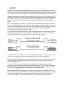
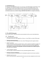
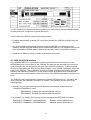
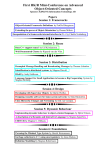
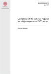
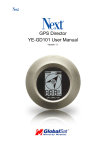
2.3 The test-configuration
The configuration of the involved test instrument and test object is shown in the figure below.
Due to the fact that the two test-instruments can’t communicate directly with each other, some
sort of translating device had to be built and the “?” box below shows the device that this
report is all about.
Rohde
DECT Tester
ADPCM
data
2 Mbit/s
PCM data
Radio link
Environment chamber
Analog link
Device
to test
6
W&G AudioAnalyzer
3
ADPCM
ADPCM is a speech compression algorithm that is used in the DRA-1900 system to reduce
the number of bits needed to represent the speech data in each channel. To be able to build
this converter, some basic knowledge of the ADPCM compression algorithm is necessary and
in this chapter, we will take a deep look at how the ADPCM compression algorithm operates.
Adaptive differential pulse code modulation (ADPCM) compression is a very efficient way to
code digital waveforms. It is widely used in speech compression application because it makes
it possible to reduce the bit flow while maintaining an acceptable level of quality. ADPCM is
also used for other types of data like data-storage, image, high-quality audio and modem
data.
The use of ADPCM compression in, for example telecommunication exchanges can double
the number of callers per trunk and therefore double the profit for the operator. We can now
send two 32 kbit/s ADPCM voice connections over a standard 64 kbit/s connection instead of
just sending one connection. It is also quite easy and cheap to implement ADPCM
compression in the existing telephone system.
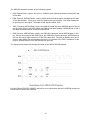
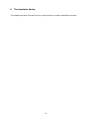
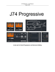
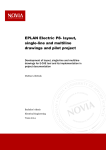
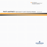
The picture below shows the benefits of using ADPCM compression in the telephone system.
Instead of just being able to send two calls on two 64kbit/s channels, we can now with the
help of ADPCM send four calls at the same time over the same channels.
Exchange
Without ADPCM
Caller A
Exchange
Receiver A
two 64 kbit/s channel
Caller B
Caller A
Caller B
Caller C
Caller D
Receiver B
Exchange
With ADPCM
two 64 kbit/s channel
Exchange
Receiver A
Receiver B
Receiver C
Receiver D
The basic principle of ADPCM is to use our knowledge of the signal in the past time to predict
it in the future and the resulting compressed signal is the error of this prediction.
Many different ADPCM algorithms have been proposed and we are in this report only dealing
with the 32 kbit/s ADPCM recommendation G.726 from CCITT that is widely used in the
telecommunication world.
The CCITT (The International Telegraph and Telephone Consultative Committee) is a
permanent organ of the International Telecommunication Union (ITU). They are responsible
for studying technical, operating and tariff question and issuing recommendations on them
with a view to standardizing telecommunications on a worldwide basis.
Implementing ADPCM compression can be done in either software or hardware and in this
report we are using a single ADPCM hardware chip that handles all the conversion. G.726 has
an effective bandwidth of 4Khz when operating at 32kbit/s datarate. One advantage with
G.726 ADPCM compression compared with other algorithms is the low signal delay.
7
3.1 ADPCM recommendation G.726
This recommendation deals with the conversion of a 64 kbit/s A-Law or µ-Law pulse code
modulation (PCM) channel to and from a 40, 32, 24 or 16 kbit/s channel. The conversion is
applied to the PCM bit stream using an ADPCM transcoding technique. Note that we are only
referring to the 32 Kbit/s ADPCM version in this report.
The CCITT ADPCM was designed to meet several specific requirements, the design goals
were to:
•
•
•
•
•
Provide compression while satisfying the objective signal quality requirements specified in
the CCITT recommendation G.712.
Have a high enough level of subjective quality (defined by listening tests) even after a
series of encodings and decodings.
Provide compatibility with the existing A-Law and µ-Law PCM formats.
Operate stable in the presence of high bit-error rates during transmissions.
Operate properly on the presence of voiceband data (modems) at rates up to 4.8 Kbit/s.
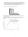
The block diagrams below shows a simplified version of the ADPCM compression encoder
and decoder:
8
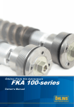
ADPCM Encoder
The purpose of the ADPCM encoder is to convert the 8-Bit PCM A-Law or µ-Law data to 4-bit
ADPCM data. The block schematic below shows the structure of the ADPCM encoder:
The encoder starts with a conversion of the A-Law or µ-Law PCM input signal to uniform
PCM. After that a difference signal is obtained, by subtracting an estimate of the input signal
from the input signal itself. An adaptive 15 level quantizer is then used to assign 4 binary digits
to the value of the difference signal. The resulting 4 bits are then send to the output of the
encoder and to the adaptive predictor.
An inverse quantizer produces a quantized difference signal from the output of the encoder.
The signal estimate is added to this quantized difference signal to produce the reconstructed
version of the input signal. Both the reconstructed signal and the quantized difference signal
are fed into an adaptive predictor who produces the estimate of the input signal, thereby
completing the feedback loop.
9
3.2 ADPCM Decoder
The purpose of the ADPCM Decoder is to convert the 4-bit ADPCM data to 8-Bit PCM A-Law
or µ-Law data. The decoder includes a structure identical to the feedback portion of the
encoder, together with a uniform PCM to A-Law or µ-Law conversion and a synchronous
coding adjustment unit. The synchronous coding adjustment prevents cumulative distortion
occurring on synchronous tandem codings (ADPCM-PCM-ADPCM, etc. digital connections),
3.3 The ADPCM internals
As you can se above, ADPCM contains several subparts and they are all described below:
3.3.1
Encoder parts
•
Input PCM format conversion
This block converts the input signal from A-Law or µ-Law PCM to a uniform PCM signal.
•
Difference signal computation
Calculated the difference signal from the uniform PCM signal and the signal estimate.
•
Adaptive quantizer
This is a non-uniform adaptive quantizer that is used to quantize the difference signal into
15 discrete levels. Prior to quantization, the signal is converted to a base 2 logarithmic
representation and scaled by a factor from the scale and speed factor adaptation block.
The reason for quantizing in the logarithmic domain is becuase a more uniform signal-tonoise ratio can be achived.
•
Inverse adaptive quantizer
Here the signal is transformed back from the quantized logarithmic domain.
•
Quantizer scale factor adaptation
This block computes the scaling factor for the adaptive quantizer and inverse quantizer.
•
Adaptation speed control
Here a control parameter is generated that tells the scale factor adaptation block the rate10
of-change of the signal. The rate-of-change speed is used to tell if the input signal is a
slow speech signal or faster voiceband data signal. The speed-control factor weights the
fast and the slow adaptation factors for form a single quantization scale factor.
•
Adaptive Predictor and Reconstructed signal calculator
This block is responsible for calculating the signal estimate that is used by the difference
signal computation block described above.
•
Tone and transition detector
This block is used to improve the performance for signals originating from frequency shift
keying (FSK) modems
3.3.2
Decoder parts
•
Output PCM format conversion
This block converts the reconstructed uniform PCM signal into an A-Law or µ-Law PCM
signal.
•
Synchronous coding adjustment
This block prevents cumulative distortion occurring on synchronous tandem coding PCMADPCM-PCM-ADPCM-PCM etc. This works when the transmission channel is error free
and when external digital signal processing does not disturb the ADPCM data.
Se the encoder parts for description on the rest of the blocks.
3.4 Adaptive predictor
Two adaptive predictors are used, as a sixth order section that models zeros and a second
order section that models poles in the input signal. This dual structure effectively caters for the
variety of input signals that might be encountered. The adaptation method used is the
feedback type and this means that no extra control information has to be transmitted with the
data. The predictor coefficients are updated using a simplified gradient algorithm. The sixthorder all-zero section helps to stabilise the filter and to prevent it from drifting into oscillation.
The predictor coefficients are updated on every sample by a simplified gradient search
algorithm.
3.5 Verification of the ADPCM encoder and decoder
The verification of ADPCM is very difficult to perform due to the adaptive nature of the
ADPCM algorithm. This means that there is almost an infinite number of possible test
sequences.
To avoid having to test all possible test sequences CCITT have pre-generated digital test
sequences that are used to verify the conformance of an ADPCM implementation. These
sequences have been chosen to exercise the major arithmetic parts and thus giving a
reasonable level of confidence of the implementation. Special reset-sequences are used
before for every test to reset the ADPCM converter into a default know state. Otherwise, the
results would not always be the same.
11
The test sequences consists of 39 different test sequences and they divided in the following
three categories:
1. A general set of various sinusoidal input PCM signals
2. Overload vectors, consisting of very high level input PCM signals
3. Special sequences that exercise the ADPCM algorithm in a manner that is not possible
with a normal PCM input sequence.
3.6 ADPCM performance
The performances of ADPCM channels are very signal dependent and random signals like
data transmissions should be avoided. ADPCM compressed links are not suitable for high
speed data transmissions and only transmissions up to 2400 bit/s can be used without serious
degradation of the transmission speed.
ADPCM systems are affected differently by bit errors than PCM systems because the ADPCM
decoder loop causes error propagation, while a PCM error does not propagate in time.
Under error free transmission conditions the perceived quality of transmitted speech over 32
kbit/s ADPCM links is only slightly lower than that over 64 kbit/s PCM links. However, when
the transmission error ratio is higher than 104 bits/error the perceived quality of speech over
32 kbit/s ADPCM links is better than that over 64 kbit/s PCM links.
12
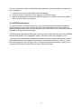
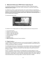
4
Rohde & Schwarz Digital Radio Communication Tester
The Rohde & Schwarz Digital Radio Communication Tester CMD-60 is a flexible instrument
that is used when performing tests on DECT compatible devices. The instrument is used at
Flextronics in the testing of the customers DECT products.
The CMD-60 instrument can for example test the following parameters on a DECT-device:
•
•
•
•
•
•
•
•
•
Accuracy and stability of the RF-carrier
Timing jitter and accuracy
Reference timing accuracy of a RFP (Radio Fixed Part, a DECT-device)
Packet accuracy and delay
Transmission burst
Transmitted power
RF carrier modulation
Radio receiver reference sensitivity
frame and Bit error
The CMD-60 instrument looks like this:
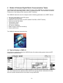
4.1 Typical displays of CMD 60
Here are two examples of what the CMD-60 looks like when making power-ramp and RFmodulation measurements.
Power ramp measurement gives in-depth analysis of the burst power transmitted by the DECT
unit. The measurement is synchronized to bit P0, thus giving precise information not only
about the power transmitted but also about timing parameters.
13
The RF modulation measurement menu presents in a scope picture the demodulated signal
for easy and quick recognition of typical data forms.
In this project the CMD-60 have the following purposes:
1. Establish and maintain a reliable RF connection between the CMD-60 and DAU while the
test lasts.
2. Act as a transparent bridge that passes through the ADPCM voice data that is sent
between the DAU and the CMD-60 to the external ADPCM-port. The translation device will
then translate the ADPCM data to PCM-format and then feed it to the W&G instrument.
3. Generate the 8KHz sync that is used to synchronize the system.
4.2 CMD-60 ADPCM interface
On a standard CMD-60, it is possible to connect external devices that can listen to the
ADPCM data sent from the DAU to the CMD-60. The data can be extracted from the 50-pin
multi-connector that can be found on the rear of the CMD-60 instrument. To allow external
devices to send data to the DAU via the CMD-60 some sort of internal modification has to be
made to the CMD-60. The modification is made by Rohde & Schwarz themself to avoid any
warranty and calibration problems. For this project, Rohde & Schwarz have modified one
instrument and it is now possible to have full control of the ADPCM data send to and from the
DAU.
The CMD-60 must be configured to activate the external ADPCM-input pin. This has to be
done every time the CMD-60 is turned-on or reseted. The activation can be done in the
following ways:
1. Manually, by using the following special undocumented escape sequences in the
”connection Established” menu.
”EE00000000”, Disables the external ADPCM input pin.
”EE01000000”, Enables the external ADPCM input pin.
2. By software, by sending the following special undocumented IEEE-488 commands:
SEND:DECT:COMMAND ”100E2008002000”
SEND:DECT:COMMAND ”100E2008000020”
14
Enables external ADPCM input
disables external ADPCM input
The ADPCM-interface consists of the following signals:
• DCK (Digital Clock, output), this is the 1.152MHz clock signal that defines the transfer rate
of the data.
• RAS (Receive ADPCM Strobe, output), 8kHz synchronization signal, that defines the start
of the data transfer. This sync is used for synchronizing this project. The PCM-5 bases all
its operation on this signal. The width of this signal is about 10µs.
• TAD (Transmitt ADPCM Data, input), the CMD-60 reads the serial ADPCM data on this pin.
On the rising edge of the RAS signal, the CMD-60 will start reading 4 ADPCM bits on the 4
first high-to-low transitions of the DCK data clock.
• RAD (Receive ADPCM Data, output), the CMD-60 outputs the serial ADPCM data on this
pin. On the rising edge of the RAS signal, the CMD-60 will start transmit 4 ADPCM bits on
the four first low-to-high transitions of the DCK data clock. The data is actually sent out 12
times in each 8KHz time slot because there are 12 timeslots in the DECT standard. In this
project, all data after the four ADPCM bits are ignored.
The figure below shows the timing and format of the above ADPCM signals:
See the Philips PCD5032 CODEC manual for more information about the ADPCM timing and
format that is used by the CMD-60.
15
5
Wandel & Goltermann PCM Channel measuring set
The Wandel & Goltermann PCM Channel measuring set PCM-5 is a general-purpose
telecommunication test instrument that is used in this project for making the actual audio
measurements of the DAU.
The PCM-5 are reference measuring sets which can be used to determine characteristics
between the analog and digital levels ("half-channel" measurements) with excellent speed and
precision. The instruments include built-in self-tests and calibration routines to handle the
demanding requirements that the digital systems used in transmission and switching makes of
test and measurement equipment.
The instrument looks like this:
The PCM-5 can for example perform the following measurements with a high precision:
•
•
•
•
•
•
•
•
•
Level measurements
Overall loss, echo return loss
Variation of gain with frequency
Variation of gain with input level
Total and harmonic distortion
Idle channel noise
Crosstalk
Overload capacity
Digital error measurements and frame evaluations
5.1 Digital Interface:
To communicate with the W&G instrument, we are using the standard E1 2.048Mbit/s PCMinterface. This type of interface is very common in telecommunication environments and it is
normally used between telephone exchanges.
The 2.048 Mbit/s PCM (Pulse Code Modulation) communication standard is defined by CCITT
and can transmit 30 telephone or data channels in each direction over a digital 2.048 Mbit/s
channel. This type of channel is also called E1 and used mainly in Europe and some nonEuropean countries.
Each E1 2.048 Mbit/s channel carries 30 voice/data plus two auxiliary channels. The two
auxiliary channels are used for framing, synchronization and signaling between the transmitter
and receiver. Everything sent on the E1 channel is grouped in frames. Each frame contains an
8-bit sample of each channel and the transmitter sends 8000 frames every second. 8-Bits per
frame and 8000 frames a second generates an effective data rate of 64 Kbit/s.
16
When voice data is sent over a channel, a compression standard called A-Law is applied to
the signal. The A-Law standard is defined in the ITU-T recommendation G. 711. For more
detailed information about the A-Law and PCM, see the CCITT/ITU-T standards. Knowledge
of the PCM format and nomenclature of the E1 operating environment are necessary when
constructing around this communication system.
A PCM channel can be configured in many different ways and in this project, we are using the
following settings:
•
•
•
•
•
•
•
A-Law compressed data.
HDB-3 digital transmission line encoding.
75-Ohm coaxial transmission cables.
Timeslot 0 and 16 are used for synchronizing and signaling.
W&G instrument is externally synchronized.
Timeslot 1 is used for data transmission, all other slots are unused.
2.048MBit/s bitrate
17
6
The translator device
This chapter has been removed from this report because it contains classified information.
18
7
PCM measurements
Several transmission measurements are used when measuring the transmission
characteristics of a pulse code modulation (PCM) channel. How to perform these
measurements has been standardised by the CCITT (the international telegraph and
telephone consultative committee).
The PCM channel-measuring instrument from Wandel & Goltermann that is used in this
project can perform most of these measurements. More detailed information can be read in
the G.712 and G.714 standard from CCITT and the W&G operating manual.
This chapter will deal only with the measurements that are used in this project.
7.1 PCM Level measurements
Here the received level of the sent signal is measured and by using this test it is possible to
get an overall view of what happens to the signal level as it passes through the system.
7.2 Overall loss
This loss measurement measures the level difference between the expected and the actually
received level.
This measurement is performed by first internally connecting the signal generator directly to
the receiver. The received level is measured and after that the internal loop is opened and a
second measurement is made through the external test object. The result is the difference in
level between the internal measurement and the external measurement. The reason for doing
this is that the attenuation characteristics of the generator and receiver should not influence
the result.
7.3 Variation of gain with frequency
This measurement shows the variation of gain at different frequencies. First a reference level
is measured at a fixed reference frequency. Then a single frequency sweep is performed and
the result is the difference between the reference level and the level measured at the different
frequencies.
7.4 Variation of gain with input level
With this measurement, it is possible to measure linearity of the test-object. First a reference
level is measured at a fixed reference level and frequency. Then a single level sweep is
performed at the same frequency and the result is the difference between the reference level
and the level measured at the different levels.
7.5 Total distortion including quantization distortion
Here the total distortion and the quantization distortion of the system are measured.
Quantization distortion occurs for example when a:
•
•
•
Analog signal is sampled and described with discrete values.
Digital linear signal is compressed/decompressed with A-Law or µ-Law
Digital PCM signal is compressed/decompressed with ADPCM
There are two methods used when measuring the quantizing distortion:
19
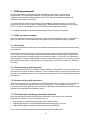
1. A band-limited noise signal with a power-spectrum within the range 350 Hz to 550 Hz. is
applied to the input port of a channel. The signal-to-total distortion power is then measured
as the ratio of the power in the frequency range 350-550Hz and in the 800-3400 Hz range.
The noise in the 800-3400Hz range is caused by the quantizing distortion.
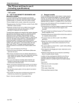
2. Here the noise signal is replaced with a sinusoidal signal with the frequency 1020 Hz.
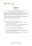
The picture below shows the principles for the measurement:
Level (dB)
Sent noise signal
S/Q
Measured Quantizing
distortion
Freq. (Hz)
The resulting distortion is measured as the level difference between the test signal and the
received quantized signal.
The diagram below shows the results of an quantizing distortion measurement on a error-free
PCM channel. The ripple in the graph is caused by the quantizing noise and the A-Law
compression.
20
8
Evaluations
The resulting measurements in this chapter have been removed because they contain
classified information.
Several measurements were done on the device to verify that the device operated as
expected. All the tests were performed using the W&G instrument that were acting as a signal
generator and a signal analyser at the same time. The result of the tests was very satisfying
and the results were checked and confirmed by one of Flextronics own measurement experts.
See the PCM measurement chapter for information about the various PCM-measurements
that are described in this chapter.
8.1 Evaluation of the PCM interface using bit-error tests
To test the 2.048 Mbit/s PCM interface we used the bit-error test function on the W&G
instrument. The W&G instrument can perform various kinds of bit-error measurements and in
this test, we used the pseudo random bit-generator to generate the test-sequences. The
schematic below shows the configuration of the bit-error test.
W&G
instrument
PCM Channel
2.048 Mbit/s
PCM interface
After running this test for over 30 minutes we found that no bit errors were detected and this
means that we can be quite confident that there’s no interfering distortions or bit-slips.
Performing a PCM->ADPCM->PCM bit-error test is not possible due to the destructiveness by
the ADPCM compression.
8.2 Evaluation of the PCM interface using audio tests
To ensure that there were no audio-distortions on the PCM-part of the design we compared
the results of various audio-measurements of the two configurations below.
W&G
instrument
W&G
instrument
PCM Channel
2.048 Mbit/s
PCM interface
PCM Channel
2.048 Mbit/s
PCM interface
No difference in the two above configurations was detected and now when the bit-error and
audio tests have passed, we can be very confident that we have a reliable PCMcommunication.
21
8.3 Evaluation of the ADPCM compression using audio tests
The following test configuration was used in this test:
PCM
W&G
instrument
PCM Channel
2.048 Mbit/s
PCM interface
ADPCM
ADPCM
converter
To evaluate the performance of the ADPCM converter we performed the same tests as we did
above when we tested the PCM channel. The result shows that the performance is dropping a
little due to the ADPCM converter, but it is still within acceptable limits.
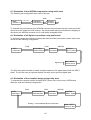
8.4 Evaluation of all digital connections using audio tests
To test all the digital connections (including the radio and DAU) we used the same audio tests
above and the following configuration:
PCM
PCM
CMD-60
DECT Tester
ADPCM
converter
Digital loop
DAU - DECT
Device to test
The DAU was patched inside to enable a digital loopback of the digital data to/from the DECTtester. The results were as expected exactly the same as the previous digital tests.
8.5 Evaluation of the complete design using audio tests
To evaluate the complete system including DECT-tester, DAU (unit to test), ADPCM and
W&G we used the following configuration:
PCM
PCM
W&G
instrument
2.048 Mbit/s
PCM interface
ADPCM
ADPCM
converter
Analog - 2 wire standard phone connection
22
CMD-60
DECT Tester
DAU - DECT
Device to test
Digital radio link
2.048 Mbit/s
PCM interface
W&G
instrument
ADPCM
The signal path in this configuration includes PCM, ADPCM and analog connections, this
means that there are many sources of errors when performing these measurements. In this
test we are using two different measurement modes, Digital->Analog and Analog->Digital
tests. These modes represent the two different measurement directions that can be measured
in a DECT system.
The result shows that measurements in both directions are matching well, except at the lower
frequencies/levels where there is some difference. This is due to the quantization and
compression of the signals.
23
9
Conclusion
I only had one major problem in developing this product and that was the lack of accurate
documentation on the CMD-60 ADPCM interface. I spent over 5 weeks investigating why the
ADPCM data received by the CMD-60 was corrupted by noise. During this time, i reconfigured
the design over 10 times and it was very frustrating not being able to solve the problem.
I found the solution on my last week at Flextronics and it turned out that there was an
undocumented inverting schmittrigger circuit on the ADPCM input stage. This meant that I had
to externally invert the ADPCM data send to the CMD-60. After adding this inverter, everything
worked fine and as planned. I found this bug by analysing the digital data stream sent over the
radio.
I learned my lesson that i should never trust written documentation, since it actually can
contain serious errors.
After solving this problem, I finally had a clean, reliable and simple design that did exactly as
planned. The result of the tests was very satisfying and the results were checked and
confirmed by one of Flextronics own measurement experts. Flextronics now have the solution
to their measurement problem and they can now start testing the DAU-product the way they
wanted to in the first place.
24
10
References
10.1 Databooks and manuals
• Design and evaluation of an interface for DECT audio testing, bachelor thesis number BEE
96-08 by Tore Nestenius, University of Karlskrona/Ronneby , August 1996.
• Object specifications, ADPCM CODEC for Digital Cordless Telephone PCD5032 from
Philips semiconductors.
• Wandel & Goltermann PCM-5 operating manual, BN 0984/00.71
• Operating manual for CMD60 digital radiocommunication tester for DECT 1050.9008.60
from Rohde & Schwarz
• Telecommunications Data Book from Dallas Semiconductor. (DS2164Q)
• DSP56000, Digital signal Processor family manual, DSP56KFAMUM/AD
• DSP56002, Digital Signal Processor user’s manual, DSP56002UM/AD rev1
• Digital Signal Processing using the Motorola DSP Family written by Robert J. Simpson,
ISBN 0-13-490632-2, Prentice Hall
• Motorola Semiconductors, DSP Application Notes
• DRA 1900, System manual, LZB 133 130 P1C, by Ericsson Business Network AB
• Digital Coding of Waveforms, principles and Applications to speech and video written by
N.S. Jayant - Peter Noll, ISBN 0-13-211913-7
• Advanced electronic communications systems written by Wayne, Tomasi, Prentice Hall,
ISBN 0-13-288309-0
• Digital Transmission, Kenth Lindgren, Liber utbildning, ISBN 91-634-0049-9
25
10.2 WWW references
http://www.programmersheaven.com
http://www.motorola.com
http://www.hp.com
http://www.wg.com
http://www.dalsemi.com
http://htsa.htsa.hva.nl/~arjanj/dect.htm
http://www.mitel.com
http://www.eg3.com/dsp.htm
http://www.analog.com
http://www.burr-brown.com
http://www.natinst.com
http://www.tapr.org/dsp
Programmers Heaven
Motorola
Hewlett Packard
Wandel & Goltermann, Inc.
Dallas Semiconductors
DECT homepage
Mitel
DSP Internet Resource List
Analog Devices
Burr-Brown Corporation
National Instruments
DSP Experimenter's Page
10.3 Standards & recommendations
• ITU-T recommendations G. 701, Vocabulary of digital transmission and multiplexing, and
pulse code modulation (PCM) terms.
• ITU-T recommendations G. 703, Physical/Electrical characteristics of hierarchical digital
interfaces.
• ITU-T recommendations G. 711, Pulse Code Modulation (PCM) of voice frequencies (ALaw)
• ITU-T recommendations G. 712, Transmission performance characteristics of pulse code
modulation.
• ITU-T recommendations G. 726, 40, 32, 24, 16 kbit/s Adaptive Differential Pulse Code
modulation (ADPCM)
• Technical Basis for Regulation (TBR) 10, DECT general terminal attachment requirements:
Telephony applications.
•
European Telecommunication Standards (ETS) 300 175-8, Digital European
Telecommunications (DECT) Common Interface (CI); Part 8: speech coding and
transmission.
26
11
Component list
11.1 Component list for this project
11.1.1
Resistors:
R1, R2, R3, R4
R5, R6, R7, R8
R9-R13, R17
R14-R16
11.1.2
Capacitors:
C1, C2, C3, C4, C5
C6, C7
Decoupling capacitors not listed
11.1.3
D1-D2
D3
B1
0.1uF
10uF
Integrated Circuits:
IC1, IC2, IC3, IC4
IC5, IC6
IC7
IC8
11.1.4
330 Ohm
270 Ohm
4.7 Kohm
220 Ohm
HP2400 optocouplers
74HCT04
DS2164Q (ADPCM Transcoder)
74HC241 Buffer
Various components
Greed LED
Red LED
Dallas DS2153Q Evaluation board
27
12
Schematics
This chapter has been removed from this report because it contains classified information.
28