1
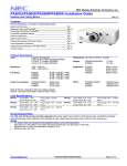
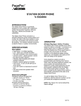
QUALITY ASSURANCE/QUALITY CONTROL DOCUMENTATION SERIES
TITLE
SERVICING AND CALIBRATION OF OPTICAL MONITORING
DATALOGGERS
TYPE
STANDARD OPERATING PROCEDURE
NUMBER
4250
DATE
MARCH 1994
AUTHORIZATIONS
TITLE
NAME
ORIGINATOR
James H. Wagner
PROJECT MANAGER
James H. Wagner
PROGRAM MANAGER
David L. Dietrich
QA MANAGER
Gloria S. Mercer
SIGNATURE
OTHER
REVISION HISTORY
REVISION
NO.
1.0
CHANGE
DESCRIPTION
Add responsibilities and equipment.
DATE
May 1996
AUTHORIZATIONS
Number 4250
Revision 1.0
Date MAY 1996
Page i of i
TABLE OF CONTENTS
Section
Page
1.0
PURPOSE AND APPLICABILITY
1
2.0
RESPONSIBILITIES
1
2.1
2.2
2.3
2.4
1
2
2
2
3.0
4.0
5.0
Project Manager
Instrument Technician
Data Coordinator
Field Specialist
REQUIRED EQUIPMENT AND MATERIALS
2
3.1
3.2
3.3
2
3
3
Campbell 21X Datalogger
Handar 540A/570A DCP
Primeline 6723 Strip Chart Recorder
METHODS
4
4.1
4.2
4.3
4
4
5
Campbell 21X Datalogger Servicing Procedures
Handar 540A/570A DCP Servicing Procedures
Primeline 6723 Strip Chart Recorder Servicing Procedures
REFERENCES
5
Number 4250
Revision 1.0
Date MAY 1996
Page 1 of 5
1.0
PURPOSE AND APPLICABILITY
This standard operating procedure (SOP) outlines the general procedures for servicing and
calibrating dataloggers used with optical monitoring systems. Accurate and reliable operation of
on-site dataloggers is critical to collection of high quality optical monitoring data. Regular
servicing, performance testing, and calibration of dataloggers is performed to assure quality data
capture and minimize data loss by:
• Performing functional checks and performance tests annually.
• Performing preventive maintenance servicing annually.
• Recalibrating the datalogger when performance tests indicate the unit is not operating
within specifications.
• Documenting all servicing, repairs, and calibrations performed.
The following technical instructions (TIs) provide detailed information regarding specific
datalogger servicing and calibration procedures:
• TI 4250-2000
Servicing and Calibration of Campbell 21X Dataloggers
• TI 4250-2010
Servicing and Calibration of the Handar 540A/570A DCP
• TI 4250-2020
Servicing and Calibration of Primeline 6723 Strip Chart Recorders
Campbell 21X dataloggers are used as the primary datalogger for the IMPROVE
nephelometer network, transmissometer calibration, and transmissometer field audits. Handar
540A/570A DCPs are used as the primary datalogger in the IMPROVE transmissometer network.
Primeline 6723 strip chart recorders are used as backup dataloggers in the IMPROVE
transmissometer network.
2.0
RESPONSIBILITIES
2.1
PROJECT MANAGER
The project manager shall:
• Ensure that performance testing is conducted on all data dataloggers annually.
• Ensure that fully serviced, calibrated, and field ready dataloggers are available as
backups for units operating in the field.
• Ensure that all dataloggers that do not operate within factory specifications are returned
to the manufacturer for factory servicing and recalibration.
• Ensure that all servicing and calibration is performed and documented according to
procedures described in the datalogger-specific servicing and calibration TIs.
Number 4250
Revision 1.0
Date MAY 1996
Page 2 of 5
2.2
INSTRUMENT TECHNICIAN
The instrument technician shall:
• Perform all servicing and calibration of optical monitoring dataloggers.
• Coordinate with the manufacturer for return of dataloggers that fail to operate within
factory specifications.
• Document and archive all datalogger servicing records.
2.3
DATA COORDINATOR
The data coordinator shall:
• Inform the instrument technician when a datalogger is removed from the field.
• Provide the instrument technician with a description of the field problems observed with
the datalogger.
2.4
FIELD SPECIALIST
The field specialist shall:
• Perform strip chart recorder checks annually.
• Provide the instrument technician with a description of problems observed during annual
site visit testing.
3.0
REQUIRED EQUIPMENT AND MATERIALS
The following subsections provide summary lists of test equipment and materials required
to service and calibrate optical monitoring dataloggers.
3.1
CAMPBELL 21X DATALOGGER
• Calibrated voltage source
• Campbell Scientific datalogger communications software (SMCOM)
• Campbell Scientific SC532 Peripheral Interface Module
• ARS Campbell 21X datalogger test program (21X_TEST.DLD)
• Digital voltmeter
• Waveform generator
• Frequency counter
• Campbell Scientific, Inc. 21X Micrologger Operator's Manual and 21X Prompt Sheet
Number 4250
Revision 1.0
Date MAY 1996
Page 3 of 5
• Reference thermometer (°C)
• Replacement components as required
• Battery pack
• Battery charger
• Desiccant packets
• Standard electronics laboratory small tools
• TI 4250-2000, Servicing and Calibration of Campbell 21X Dataloggers
3.2
HANDAR 540A/570A DCP
• Calibrated voltage source
• RF Wattmeter with 50 ohm RF load
• Digital voltmeter
• Reference AT/RH sensor
• Handar, Inc. Operating and Service Manual for 540A Multiple Access Data Acquisition
System, 560A Hydrologic Data Collection System, and 545A Programming Set
• Handar, Inc. 570A Data Acquisition System Operating and Service Manual
• Handar "TERM" program
• IBM PC-compatible computer
• Spare circuit boards as required
• 12 volt battery
• Desiccant packets
• Standard electronics laboratory small tools
• TI 4250-2010, Servicing and Calibration of the Handar 540A/570A DCP
3.3
PRIMELINE 6723 STRIP CHART RECORDER
• Regulated 12 VDC power supply
• Calibrated voltage source
• Digital voltmeter
Number 4250
Revision 1.0
Date MAY 1996
Page 4 of 5
• Frequency counter
• Standard electronics laboratory small tools
• Soltec Distribution, Primeline 6723 Instruction Manual
• Stopwatch
• Replacement components (fuses, chart pens, chart paper)
• Cleaning supplies (window cleaner, alcohol, foam tip swabs)
• TI 4250-2020, Servicing and Calibration of Primeline 6723 Strip Chart Recorders
4.0
METHODS
This section includes three (3) subsections:
4.1 Campbell 21X Datalogger Servicing Procedures
4.2 Handar 540A/570A DCP Servicing Procedures
4.3 Primeline 6723 Strip Chart Recorder Servicing Procedures
4.1
CAMPBELL 21X DATALOGGER SERVICING PROCEDURES
Campbell 21X dataloggers are used as the primary datalogger for the IMPROVE
nephelometer network, transmissometer calibration, and transmissometer field audits. Servicing
procedures for the Campbell 21X datalogger are described in detail in TI 4250-2000, Servicing
and Calibration of Campbell 21X Dataloggers. Servicing procedures include:
• Internal memory check
• Analog input check
• Analog output check
• Pulse counter check
• Panel temperature check
• Internal battery servicing
• Archiving Campbell 21X datalogger service records
4.2
HANDAR 540A/570A DCP SERVICING PROCEDURES
The Handar 540A/570A DCP is the primary datalogger in the IMPROVE transmissometer
network. Servicing procedures for the Handar 540A/570A DCP are described in detail in TI
4250-2010, Servicing and Calibration of the Handar 540A/570A DCP. Servicing procedures
include:
• Post-field inspection and performance checks
Number 4250
Revision 1.0
Date MAY 1996
Page 5 of 5
• Routine laboratory servicing
• DCP programming
• Pre-field performance testing
• Archiving Handar 540A/570A DCP service records
4.3
PRIMELINE 6723 STRIP CHART RECORDER SERVICING PROCEDURES
The Primeline 6723 strip chart recorder is used as the backup recorder in the IMPROVE
transmissometer network. Servicing procedures for the Primeline 6723 strip chart recorder are
described in detail in TI 4250-2020, Servicing and Calibration of Primeline 6723 Strip Chart
Recorders. Servicing procedures include:
• Post-field inspection and performance checks
• Routine servicing
• Pre-field calibration and testing
• Archiving Primeline 6723 strip chart recorder service records
5.0
REFERENCES
Campbell Scientific, Inc., 1993, 21X Micrologger Operator's Manual. July.
Campbell Scientific, Inc., 1993, 21X Prompt Sheet.
Handar, Inc., 1982, Operating and Service Manual for 540A Multiple Access Data Acquisition
System, 560A Hydrologic Data Collection System, and 545A Programming Set. June.
Handar, Inc., 1988, 570A Data Acquisition System Operating and Service Manual. March.
Soltec Distribution, Primeline 6723 Instruction Manual.
QUALITY ASSURANCE/QUALITY CONTROL DOCUMENTATION SERIES
TITLE
SERVICING AND CALIBRATION OF CAMPBELL 21X DATALOGGERS
TYPE
TECHNICAL INSTRUCTION
NUMBER
4250-2000
DATE
FEBRUARY 1994
AUTHORIZATIONS
TITLE
NAME
ORIGINATOR
James H. Wagner
PROJECT MANAGER
James H. Wagner
PROGRAM MANAGER
David L. Dietrich
QA MANAGER
Gloria S. Mercer
SIGNATURE
OTHER
REVISION HISTORY
REVISION
NO.
1.0
CHANGE
DESCRIPTION
Add data coordinator respon./update format
DATE
May 1996
AUTHORIZATIONS
Number 4250-2000
Revision 1.0
Date MAY 1996
Page i of i
TABLE OF CONTENTS
Section
Page
1.0
PURPOSE AND APPLICABILITY
1
2.0
RESPONSIBILITIES
1
2.1
2.2
2.3
1
2
2
Project Manager
Instrument Technician
Data Coordinator
3.0
REQUIRED EQUIPMENT AND MATERIALS
2
4.0
METHODS
3
4.1
4.2
4.3
4.4
4.5
4.6
4.7
3
5
5
6
6
6
7
5.0
Internal Memory Check
Analog Input Checks
Analog Output Checks
Pulse Counter Check
Panel Temperature Test
Internal Battery Servicing
Archiving Datalogger Service Records
REFERENCES
7
LIST OF FIGURES
Figure
4-1
Campbell 21X Datalogger Servicing Documentation Form
Page
4
Number 4250-2000
Revision 1.0
Date MAY 1996
Page 1 of 7
1.0
PURPOSE AND APPLICABILITY
This technical instruction (TI) describes procedures for servicing and verifying calibration
of Campbell 21X dataloggers. This TI, as referenced in Standard Operating Procedure (SOP)
4250, Servicing and Calibration of Optical Monitoring Dataloggers, specifically describes
procedures for:
• Testing datalogger memory functions
• Checking the accuracy of all analog voltage input channels
• Checking the accuracy of the analog output ports
• Checking the accuracy of the pulse input port
• Checking the accuracy of the panel temperature measurement
• Checking the condition of the internal battery
• Replacing the internal battery
• Archiving datalogger servicing records
Campbell 21X dataloggers are primarily used by ARS as the:
• Primary datalogger at NGN-2 nephelometer monitoring sites (Refer to TI 4300-4006,
Nephelometer Data Collection via Campbell Scientific Data Storage Module
(IMPROVE Protocol)).
• Primary datalogger for transmissometer calibration (Refer to TI 4200-2100, Calibration
of Optec LPV-2 Transmissometers (IMPROVE Protocol)).
• Primary datalogger for field audit of transmissometers (Refer to SOP 4710,
Transmissometer Field Audit Procedures).
2.0
RESPONSIBILITIES
2.1
PROJECT MANAGER
The project manager shall:
• Verify that all Campbell 21X dataloggers are serviced at least annually.
• Verify that calibration checks are performed on all Campbell 21x dataloggers at least
annually.
• Verify that all Campbell 21X dataloggers are operating within factory specifications
prior to being shipped to the field.
• Verify that all Campbell 21X dataloggers that do not operate within factory
specifications are returned to Campbell Scientific for factory servicing and recalibration.
Number 4250-2000
Revision 1.0
Date MAY 1996
Page 2 of 7
• Ensure that all datalogger servicing is documented and archived in accordance with the
procedures described in this TI.
2.2
INSTRUMENT TECHNICIAN
The instrument technician shall:
• Perform and document all calibration checks.
• Coordinate with Campbell Scientific for return and recalibration of Campbell 21X
dataloggers that fail to operate within factory specifications.
• Prepare purchase orders for factory servicing and recalibration of Campbell 21X
dataloggers.
• Replace the Campbell 21X internal battery as required.
• Archive all datalogger servicing records.
2.3
DATA COORDINATOR
The data coordinator shall:
• Inform the instrument technician when a 21X is being removed from the field.
• Provide the instrument technician with a description of the field problems observed with
the 21X.
3.0
REQUIRED EQUIPMENT AND MATERIALS
Specific instrumentation, tools, equipment, and materials required to service the Campbell
21X datalogger and to verify the datalogger calibration are:
• Calibrated voltage source - Datel Model DVC-350A or equivalent
• Campbell Scientific datalogger communications software (SMCOM)
• Campbell Scientific SC532 Peripheral Interface Module
• ARS Campbell 21X datalogger test program (21X_TEST.DLD)
• Digital voltmeter (4 1/2 digits)
• Waveform generator - Wavetek Model 185 or equivalent
• Frequency counter - Tenma Model 72-375 or equivalent
• Campbell Scientific, Inc. 21X Micrologger Operator's Manual and 21X Prompt Sheet
• Laboratory reference thermometer (°C)
Number 4250-2000
Revision 1.0
Date MAY 1996
Page 3 of 7
• Replacement components as required
• Medium screwdrivers (flat-blade and Phillips-head)
• Battery charger
• Replacement sealed lead acid battery pack
• Two (2) dry half-unit DESI PAK desiccant packets
4.0
METHODS
Campbell 21X dataloggers should be serviced according to the following schedule:
• Prior to installation at a field monitoring site
• On an annual schedule (for units not used at field sites)
• Any time the operation or accuracy of the datalogger appears to be suspect
Calibration of the Campbell 21X datalogger is required any time calibration checks indicate
that the datalogger is not operating within factory specifications.
This section includes six (6) subsections:
4.1
4.2
4.3
4.4
4.5
4.6
4.7
Internal Memory Check
Analog Input Checks
Analog Output Checks
Pulse Counter Check
Panel Temperature Test
Internal Battery Servicing
Archiving Datalogger Service Records
Procedures for performing the internal memory check are documented on the Campbell
21X Datalogger Servicing Documentation Form (Figure 4-1) and are described in the following
sections.
RECORD
GENERAL
INFORMATION
4.1
Record the datalogger serial number and the current date. The
initials of the technician performing the inspection should also be
recorded.
INTERNAL MEMORY CHECK
The Campbell 21X datalogger will perform an internal memory check on power-up. This
check indicates the status of each memory chip on the datalogger's CPU board. Procedures for
performing the internal memory check are documented on the Campbell 21X Datalogger
Servicing Documentation Form (Figure 4-1) and are as follows:
TURN
DATALOGGER
ON
Turn the datalogger ON.
"HELLO."
The datalogger display will read
Number 4250-2000
Revision 1.0
Date MAY 1996
Page 4 of 7
CAMPBELL 21X DATALOGGER
SERVICING DOCUMENTATION FORM
Date: ___________________________
Datalogger S/N: __________________
Technician: ______________________
INTERNAL MEMORY CHECK
Memory Status = 11:111111?
!Yes !No
Status __:______
ANALOG INPUT CHECK
Datalogger Readings (mV)
Input
Voltage (mV)
0.000
2.500
5.000
CH1
CH2
CH3
CH4
CH5
CH6
CH7
CH8
ANALOG OUTPUT CHECK
CAO PORT #
#1
#2
CORRECT OUTPUT (mV)
2500±1
5000±1
ACTUAL OUTPUT (mV)
PULSE COUNTER CHECK
Waveform Generator Frequency ____________________ Hz
Datalogger Counts _______________________________
PANEL TEMPERATURE CHECK
Ambient Temperature - Lab Reference _______________ °C
Datalogger Panel Temperature _____________________ °C
INTERNAL BATTERY SERVICING
Battery Voltage ___________________________ Volts
Battery Installation Date ____________________
!Yes
!No
Battery Replaced
Desiccant Replaced!Yes !No Comment _______________________________
Factory servicing or calibration required !Yes !No
Describe Servicing required ______________________________________________
_____________________________________________________________________
_____________________________________________________________________
Figure 4-1. Campbell 21X Datalogger Servicing Documentation Form.
Number 4250-2000
Revision 1.0
Date MAY 1996
Page 5 of 7
After a few seconds delay, the memory check results will be
displayed. If all memory is installed and operating, the display will
read "11:111111." The eight (8) characters in the display represent
the eight (8) memory sockets numbered from left to right. A "1"
indicates a good chip is in the corresponding socket. A "0" indicates
the socket is empty or an error was detected in the chip. The five (5)
left-most characters of the display represent the 8K ram chips. The
three (3) right-most characters of the display are the 8K PROMs.
If the memory check results indicate that one or more memory chips
are faulty, return the instrument to Campbell Scientific for repair.
4.2
ANALOG INPUT CHECKS
CONNECT
VOLTAGE
CALIBRATOR
Connect the Datel voltage calibrator to the datalogger using the
datalogger "analog inputs" test cable. This cable provides a
connection from the voltage output of the calibrator to each of the
eight (8) analog input channels of the datalogger.
DOWNLOAD
TEST PROGRAM
Download the datalogger test program (21X_TEST.DLD) to the
datalogger to be tested using the Campbell Scientific datalogger
communications software (SMCOM) and the Campbell Scientific
SC532 Peripheral Interface Module.
RUN TEST
PROGRAM
Press *0 on the datalogger to compile and run the test program.
SET VOLTAGES
Set the calibrator to the input voltages specified on the Campbell
21X Datalogger Servicing Documentation Form (Figure 4-1). All
input voltages are specified in millivolts. All datalogger readings
should be recorded as millivolts.
RECORD
DISPLAY
READINGS
Enter *6 on the datalogger and record the datalogger display
reading (storage locations 01 - 08) for each of the eight analog
channels at each of the three input voltages specified on the
Campbell 21X Datalogger Servicing Documentation Form.
If the datalogger readings for any of the analog channels differ from
the specified values by more than ± 5.0 millivolts, return the
datalogger to Campbell Scientific for recalibration.
4.3
ANALOG OUTPUT CHECKS
The test program sets up a continuous DC voltage output on both analog output ports
(CAO 1 and CAO 2).
MEASURE
OUTPUT
VOLTAGE
Measure the output voltage at CAO ports 1 and 2 with a calibrated
and certified 4 ½ digit voltmeter. Record these measurements (in
millivolts) on the Campbell 21X Datalogger Servicing
Number 4250-2000
Revision 1.0
Date MAY 1996
Page 6 of 7
Documentation Form. The correct reading for each port is shown,
along with the manufacturers' specified accuracy, on the Campbell
21X Datalogger Servicing Documentation Form.
If the datalogger readings for either CAO port differ from the
specified values by more than ± 5.0 millivolts, return the datalogger
to Campbell Scientific for recalibration.
4.4
PULSE COUNTER CHECK
CONNECT
GENERATOR TO
FREQUENCY
COUNTER
Connect the waveform generator to pulse input channel #1.
SETUP
WAVEFORM
GENERATOR
Setup the waveform generator for a square wave output with a
frequency of 1000 Hz and an amplitude of 1 volt(rms).
RECORD
COUNTS
The test program will count pulses from the waveform generator
for a period of 10 seconds. Record the number of counts in the
pulse counter channel at storage location 09 ( press *6 9 on the
datalogger). Based on an input frequency of 1000 Hz, a datalogger
count of 10,000 should be displayed.
If the datalogger reading for the pulse counter channel differs from
the specified value by more than ± 5 counts, return the datalogger to
Campbell Scientific for recalibration.
4.5
PANEL TEMPERATURE CHECK
RECORD
AMBIENT
TEMPERATURE
Read the ambient temperature in the laboratory with the laboratory
reference thermometer. Record this temperature (°C) on the
Campbell 21X Datalogger Servicing Documentation Form (Figure
4-1).
RECORD
PANEL
TEMPERATURE
Read the datalogger panel temperature at storage location 10 (press
*6 10 on the datalogger) and record the reading on the Campbell
21X Datalogger Servicing Documentation Form.
If the datalogger panel temperature measurement differs from the
laboratory reference thermometer reading by more than ± 1.7 °C,
return the datalogger to Campbell Scientific for recalibration.
4.6
INTERNAL BATTERY SERVICING
RECORD
BATTERY
VOLTAGE
Read the internal battery voltage at storage location 11 (press *6 11
on the datalogger). Record this reading on the Campbell 21X
Datalogger Servicing Documentation Form.
Number 4250-2000
Revision 1.0
Date MAY 1996
Page 7 of 7
RECHARGE
BATTERY
If the battery voltage is less than 11.76 volts, connect the
datalogger to the battery charger. Recharge the battery for eight (8)
hours.
REPLACE
BATTERY
Disconnect the datalogger from the battery charger and recheck the
battery voltage (press *6 11 on the datalogger). If the battery
voltage is still less than 11.76 volts, replace the battery as described
below:
• Turn the power switch OFF.
• Remove the two front panel screws and carefully raise the front
panel away from the datalogger case.
• Disconnect the used battery from the charging circuit and remove
from the datalogger case.
• Install a fresh battery. Mark the installation date on the battery.
• Remove the datalogger desiccant packets and replace with two
(2) dry half unit DESI PAK desiccant packets.
• Replace the front panel.
• Turn the power switch ON and recheck the battery voltage.
4.7
ARCHIVING DATALOGGER SERVICE RECORDS
All service records for Campbell 21X dataloggers are maintained by the instrument
technician. The records are archived by datalogger serial number in three-ring notebooks located
in the ARS instrumentation laboratory.
5.0
REFERENCES
Campbell Scientific, Inc., 1993, 21X Micrologger Operator's Manual. July.
Campbell Scientific, Inc., 1993, 21X Prompt Sheet.
QUALITY ASSURANCE/QUALITY CONTROL DOCUMENTATION SERIES
TITLE
SERVICING AND CALIBRATION OF THE HANDAR 540A/570A DCP
TYPE
TECHNICAL INSTRUCTION
NUMBER
4250-2010
DATE
FEBRUARY 1994
AUTHORIZATIONS
TITLE
NAME
ORIGINATOR
James H. Wagner
PROJECT MANAGER
James H. Wagner
PROGRAM MANAGER
David L. Dietrich
QA MANAGER
Gloria S. Mercer
SIGNATURE
OTHER
REVISION HISTORY
REVISION
NO.
0.1
CHANGE
DESCRIPTION
Updated format.
DATE
May 1996
AUTHORIZATIONS
Number 4250-2010
Revision 0.1
Date MAY 1996
Page i of ii
TABLE OF CONTENTS
Section
Page
1.0
PURPOSE AND APPLICABILITY
1
2.0
RESPONSIBILITIES
1
2.1
2.2
2.3
1
1
2
Project Manager
Instrument Technician
Data Coordinator
3.0
REQUIRED EQUIPMENT AND MATERIALS
2
4.0
METHODS
3
4.1
3
Post-Field Inspection and Performance Checks
4.1.1
4.1.2
4.1.3
4.1.4
4.1.5
4.1.6
4.2
4.3
4.4
4.5
5.0
General Information
Physical Inspection - External
Physical Inspection - Internal
DCP Timing Checks
DCP A/D Converter Checks
Transmission Test
3
6
6
6
8
13
Routine Laboratory Servicing
DCP Programming
Pre-Field Performance Testing
13
19
23
4.4.1
4.4.2
4.4.3
4.4.4
General Information
Laboratory Performance Testing
Run Mode Timing Checks
Field Testing of the Handar 540A/570A DCP
23
23
25
25
Archiving Handar 540A/570A DCP Service Records
26
REFERENCES
26
APPENDIX A HANDAR 540A DCP CONFIGURATION PROGRAM 540ROT.DCP
27
APPENDIX B HANDAR 570A DCP CONFIGURATION PROGRAM 570ROT.DCP
32
LIST OF FIGURES
Figure
4-1
Post-Field Inspection Checklist - Handar 540A/570A DCP
Page
4
Number 4250-2010
Revision 0.1
Date MAY 1996
Page ii of ii
LIST OF FIGURES (CONTINUED)
Figure
Page
4-2
Front Panel Configurations - Handar 540A/570A DCP
5
4-3
DCP Component Diagram
7
4-4
"TERM" Setup Screen
9
4-5
"TERM" DCP Programming Screen (Program in DCP Memory)
10
4-6
"TERM" DCP Programming Screen (No Program in DCP Memory)
11
4-7
Routine Servicing Checklist - Handar 540A/570A DCP
14
4-8
Handar 570A ADC Board - Component Locations
17
4-9
Handar 540A Met Board - Component Locations
18
4-10 Laboratory Performance Testing Form - Handar 540A/570A DCP
24
LIST OF TABLES
Table
4-1
Page
DCP ID Assignments, IMPROVE Transmissometer Network
20
Number 4250-2010
Revision 0.1
Date MAY 1996
Page 1 of 37
1.0
PURPOSE AND APPLICABILITY
This technical instruction (TI) describes procedures for servicing and calibration testing of
Handar 540A/570A Data Collection Platforms (DCPs). This TI, as referenced in Standard
Operating Procedure 4250, Servicing and Calibration of Optical Monitoring Dataloggers,
specifically describes procedures for:
• Performing post-field inspections
• Performing post-field timing and performance checks
• Performing routine laboratory servicing and cleaning
• Checking and performing laboratory modifications
• Programming the DCP
• Performing pre-field operational tests
• Documenting all servicing tasks
• Archiving servicing, repair, and calibration records
Handar 540A/570A DCPs are used as the primary dataloggers in the IMPROVE
transmissometer network.
2.0
RESPONSIBILITIES
2.1
PROJECT MANAGER
The project manager shall:
• Verify that all Handar 540A/570A DCPs are serviced at least annually.
• Verify that calibration, timing, and transmission checks are performed on all Handar
540A/570A DCPs at least annually.
• Verify that all Handar 540A/570A DCPs are operating within factory specifications
prior to being shipped to the field for use at an operational monitoring site.
• Verify that all Handar 540A/570A DCPs that do not operate within factory
specifications are returned to Handar for factory servicing and recalibration.
• Ensure that all DCP servicing is documented and archived in accordance with the
procedures described in this TI.
2.2
INSTRUMENT TECHNICIAN
The instrument technician shall:
• Perform and document all servicing, modifications, calibration checks, and operational
tests.
Number 4250-2010
Revision 0.1
Date MAY 1996
Page 2 of 37
• Coordinate with Handar for return, servicing, and recalibration of 540A/570A DCPs
that fail to operate within factory specifications.
• Prepare purchase orders for factory servicing and recalibration of Handar 540A/570A
DCPs.
• Replace the Handar 540A/570A internal battery as required.
• Archive all DCP servicing records.
2.3
DATA COORDINATOR
The data coordinator shall:
• Inform the instrument technician when a DCP is being removed from the field.
• Provide the instrument technician with a description of the field problems observed
with the DCP.
3.0
REQUIRED EQUIPMENT AND MATERIALS
Specific instrumentation, tools, equipment, and materials required to service and test the
Handar 540A/570A DCP are as follows:
• Calibrated voltage source - Datel Model DVC-350A or equivalent
• RF wattmeter - Bird Model 43 with #250D power element and 50 ohm RF load or
equivalent
• Digital voltmeter (4 1/2 digits)
• Handar, Inc. Operating and Service Manual for 540A Multiple Access Data Acquisition
System, 560A Hydrologic Data Collection System, and 545A Programming Set
• Handar, Inc. 570A Data Acquisition System Operating and Service Manual
• Handar "TERM" program (DCP communication and interface software)
• IBM PC-compatible computer
• Spare circuit boards as required
• Replacement internal 12 volt battery
• Two (2) packs desiccant
• Reference AT/RH sensor (Rotronics GT-L or equivalent)
• Rotronics AT/RH Sensor (Model MP-100F, wired for use with the Handar 540A/570A
DCP)
Number 4250-2010
Revision 0.1
Date MAY 1996
Page 3 of 37
• Electronic contacts cleaning fluid
• Medium screwdrivers (flat-blade and Phillips-head)
4.0
METHODS
Handar 540A/570A DCPs should be serviced according to the following schedule:
• Prior to installation at a field monitoring site
• On an annual schedule
• Any time the operation or accuracy of the datalogger appears to be suspect
Factory servicing and calibration of the Handar 540A/570A DCP is required when timing
and performance checks indicate that the DCP is not operating within factory specifications.
This section includes five (5) major subsections:
4.1
4.2
4.3
4.4
4.5
4.1
Post-Field Inspection and Performance Checks
Routine Laboratory Servicing
DCP Programming
Pre-Field Performance Testing
Archiving Handar 540A/570A DCP Service Records
POST-FIELD INSPECTION AND PERFORMANCE CHECKS
When a DCP is returned from a field site, the external and internal physical condition is
visually inspected prior to performing any performance tests or laboratory servicing. If the DCP
is received with the power switch in the "ON" position and there are no loose circuit boards,
disconnected or damaged connectors, or other apparent problems that might affect the operation
of the DCP, performance tests that evaluate DCP timing, A/D converter operation, transmission
power, and the DCP program are performed. Results and comments related to inspection and
performance testing are fully documented on the Post-Field Inspection Checklist - Handar
540A/570A DCP (Figure 4-1).
4.1.1 General Information
RECORD
GENERAL
INFORMATION
Record the DCP serial number, the site it was received from, and
the date it was received. The initials of the technician performing
the inspection should also be recorded.
IDENTIFY
DCP MODEL
Identify the DCP model (Figure 4-2 shows the front panel layout
of each of the three DCP models used by ARS).
NOTE REASON
FOR RETURN
Note whether the DCP was returned for annual servicing (no
observed operational problems in the field) or for unscheduled
maintenance (unit malfunctioning). If returned for unscheduled
maintenance, describe the observed field symptoms.
Number 4250-2010
Revision 0.1
Date MAY 1996
Page 4 of 37
POST-FIELD INSPECTION CHECKLIST
HANDAR 540A/570A DCP
DCP S/N: ______________________________
Site: __________________________________
Date: _________________________________
Technician: ____________________________
DCP Model: ¨540A1
¨540A2
¨570A
Received for: ¨Annual Servicing
¨Unscheduled Maintenance
Reason for unscheduled maintenance _____________________________________________________
____________________________________________________________________________________
____________________________________________________________________________________
PHYSICAL INSPECTION - EXTERNAL
Describe "as returned" condition of the following:
DCP Case _____________________________________________________________________
Case Latches ___________________________________________________________________
Connectors/Contacts _____________________________________________________________
Display (570A Only) ______________________________________________________________
Door Seal ______________________________________________________________________
PHYSICAL INSPECTION - INTERNAL
Describe "as returned" condition of the following:
Power switch
¨On
¨Off
GOES Radio Channel 1
¨900
¨Other ______________________________________
GOES Radio Channel 2
¨000
¨Other ______________________________________
Circuit Boards, Hold Down Bracket, Connectors ________________________________________
Battery and Hold Down Bracket _____________________________________________________
Battery Voltage ________________ Volts
DCP TIMING CHECKS
Program in Memory
¨Yes
¨No
DCP ID [I] _________________________
DCP Time [J] __ __ : __ __ : __ __
WWV Time __ __ : __ __ : __ __
DCP Time to Next Scan [S] __ __ : __ __ : __ __
DCP Time to Next Transmit [T] __ __ : __ __ : __ __
DCP A/D CONVERTER CHECKS
Test Input
Ch. 1,2,3
0.000 Volts
4.950 Volts
Lab AT/RH
DCP Channel # (Output)
CH1
CH2
CH3
CH4
CH5
CH10
_______
_______
_______
_______
_______
_______
_______
_______
_______
_______
_______
_______
_______
_______
TRANSMISSION TEST
Forced Transmit RF Power Output _____________________ Watts
Figure 4-1. Post-Field Inspection Checklist - Handar 540A/570A DCP.
Number 4250-2010
Revision 0.1
Date MAY 1996
Page 5 of 37
Figure 4-2. Front Panel Configurations - Handar 540A/570A DCP.
Number 4250-2010
Revision 0.1
Date MAY 1996
Page 6 of 37
4.1.2 Physical Inspection - External
INSPECT
CASE
Inspect the outside of the DCP case thoroughly. Look for signs of
external damage (dented, scraped, or gouged surfaces). Examine the
latches and external connectors. Describe any damage or general
deterioration noted.
RECORD
DISPLAY
If the DCP is a model 570A, step through the display, recording
the readings displayed for each channel.
INSPECT
SEAL
Open the cover on the DCP and inspect the seal between the cover
and the case. Look for loose sections of seal, tears, and worn spots.
4.1.3 Physical Inspection - Internal
NOTE POWER
Note whether the power switch is "ON" or "OFF" (see Figure 4-3
for switch location).
NOTE CHANNEL
SETTINGS
Note the settings of the GOES primary channel (#1) and secondary
channel (#2) switches (see Figure 4-3 for switch locations). The
GOES primary channel selection switch should be set to "900"
(inhibits transmission). The GOES secondary channel selection
switch should be set to "000" (channel unused). If the switches are
not set properly, they should be reset to these channel numbers
before proceeding with this inspection.
INSPECT DCP
INTERIOR
Inspect the interior of the DCP, checking that all circuit boards are
firmly seated, all hold-down brackets are in place and secure, and all
cables and connectors are undamaged and in place. Describe any
improper conditions.
MEASURE
BATTERY
VOLTAGE
Measure the internal battery voltage. If it is less than 11.8 volts,
connect a current limited power supply set at 16 volts and 500 ma
to the DCP Solar Panel/Battery Charger input for a period of 24
hours. If the battery voltage does not reach a minimum voltage of
13.8 volts, it must be replaced during servicing.
CHECK
INSTALLATION
DATE
Check the installation date on the battery. If the battery is more
than 5 years old, it must be replaced during servicing, regardless
of the battery's state of charge.
4.1.4 DCP Timing Checks
PROGRAM
NOTE! If the DCP power switch was off, or has been MEMORY
turned off for any reason, the program and timing will have been
lost from the DCP memory and this section of the post-field
inspection should be omitted.
EXECUTE
PROGRAM
Execute the Handar DCP communications program "TERM" from
the IBM PC-compatible computer.
Number 4250-2010
Revision 0.1
Date MAY 1996
Page 7 of 37
Figure 4-3. DCP Component Diagram.
Number 4250-2010
Revision 0.1
Date MAY 1996
Page 8 of 37
SWITCH
BAUD RATE
When the "TERM" setup screen (see Figure 4-4) is displayed on
the computer screen, press F2 to switch to the correct baud rate (300
baud).
CONNECT
COMPUTER
TO DCP
Connect the serial port of the computer to the DCP programming
port (see Figure 4-2 for location) using the DCP programming
cable. After the connection is complete, the "TERM" programming
screen (Figure 4-5) should be displayed on the computer screen.
NOTE
DISPLAY
If the program is still in memory, the computer display should be
as shown in Figure 4-5.
If the computer display appears as in Figure 4-6, the program
has been lost from memory and the DCP performance and
timing checks should be terminated. Exit the "TERM"
program and turn the DCP off before initiating the servicing
procedures. Be sure and document that the program was no
longer in memory.
SYNCHRONIZE
TIME
Verify that your watch is synchronized with WWV by calling the
NIST WWV time transmission telephone (303/499-7111).
ENTER
PARAMETERS
Obtain DCP ID and timing information by entering into the DCP
the boldface character that precedes each of the following
parameters:
• I
Station ID
• J
DCP time
• S
Time remaining before next scan
• T
Time remaining before next transmission
RECORD
VALUES
Record each of the values from the ID and timing checks and the
correct (WWV) time when the DCP time check, [J], was performed.
COMPARE
TIMES
Compare the DCP times to the correct time to determine the timing
drift relative to previous measurements (at installation or from
recent transmissions - Refer to TI 4300-4000, Data Collection via
DCP (IMPROVE Protocol).
4.1.5 DCP A/D Converter Checks
CONNECT
VOLTAGE
SOURCE
Connect a calibrated voltage source to the input of data channels
01, 02, and 03 of the DCP.
CONNECT
AT/RH SENSOR
Connect a calibrated Rotronic AT/RH sensor to the DCP's AT/RH
input connector.
Number 4250-2010
Revision 0.1
Date MAY 1996
Page 9 of 37
Figure 4-4. TERM Setup Screen.
Number 4250-2010
Revision 0.1
Date MAY 1996
Page 10 of 37
Figure 4-5. "TERM" DCP Programming Screen (Program in DCP Memory).
Number 4250-2010
Revision 0.1
Date MAY 1996
Page 11 of 37
Figure 4-6. TERM DCP Programming Screen (No Program in DCP Memory).
Number 4250-2010
Revision 0.1
Date MAY 1996
Page 12 of 37
SWITCH
MODES
Switch the DCP from "RUN" mode to "PROGRAM" mode by
entering ?.
The computer display will read "R Enter (1) = Service (2) = All."
Enter 2 to select "ALL."
SET OUTPUT
Set the output of the calibrated voltage source to 0.000 volts.
OBTAIN
READINGS
Obtain DCP readings for data channels 01, 02, and 03 using the
following procedure:
• Enter M (access data channel 01 - transmissometer raw readings).
• Enter $ (execute a forced scan).
• Record the DCP reading for data channel 01.
• Enter V (scroll down to data channel 02 - transmissometer toggle
signal).
• Enter $ (execute a forced scan).
• Record the DCP reading for data channel 02.
• Enter V (scroll down to data channel 03 - transmissometer
standard deviation).
• Enter $ (execute a forced scan).
• Record the DCP reading for data channel 03.
With a 0.000 volt input, DCP data channels 01, 02, and 03 should
all read "000."
SET OUTPUT
VOLTAGE
Set the output of the calibrated voltage source to 4.950 volts.
OBTAIN
READINGS
Obtain DCP readings for data channels 01-05 and 10 using the DCP
procedures described above for obtaining DCP readings for data
channels 01, 02, and 03.
OBTAIN
AT/RH
Obtain current laboratory measurements of ambient temperature and
relative humidity using the Rotronic GT-L hand held AT/RH sensor.
Record these values on the inspection checklist (DCP A/D
Converter Checks section) under channel 04 and channel 05,
respectively.
NOTE
READINGS
With a 4.950 volt input, DCP data channels 01 and 03 should read
"495." DCP data channel 02 should read "001."
Number 4250-2010
Revision 0.1
Date MAY 1996
Page 13 of 37
COMPARE
READINGS
The DCP data channel 04 reading (Rotronics AT output signal)
must be adjusted by subtracting 100 from the reading obtained
during the test. Compare this adjusted reading with the temperature
measurement obtained with the hand held sensor. The two values
should then match within ± 2 F°.
Compare the DCP data channel 05 reading (Rotronics RH output
signal) with the RH measurement obtained with the hand held
sensor. The two values should agree within ± 3%.
Compare the DCP data channel 10 reading (DCP internal battery
voltage) with the internal battery voltage measured during the DCP
internal physical inspection. The two values should agree within ±
0.005 volts.
4.1.6 Transmission Test
CONNECT
WATTMETER
Connect an RF wattmeter (with a 200-500 mHz, 25-watt power
element) to the "RF Output" connector located on the front panel of
the DCP. A 50 Ohm, 25-watt load resistor should be connected to
the output of the wattmeter.
SET CHANNEL
SWITCHES
Set the GOES primary channel select switches to the channel
number assigned to the ID programmed for the DCP under test.
INITIATE
TRANSMISSION
With the DCP in "PROGRAM" mode, initiate a transmission by
entering #.
RECORD
READING
The wattmeter should read 10 ± 2 watts. Record the observed
reading on the Post-Field Inspection Checklist - Handar 540A/570A
DCP (Figure 4-1).
RESET
SWITCHES
Reset the GOES primary channel select switches to 900.
4.2
ROUTINE LABORATORY SERVICING
Record and document all information and procedures on the Routine Servicing Checklist Handar 540A/570A DCP (Figure 4-7).
RECORD
GENERAL
INFORMATION
Record the DCP serial number, the site it was received from, and
the date it was received. The initials of the technician performing
the inspection should also be recorded.
IDENTIFY
DCP MODEL
Identify the DCP model (Figure 4-2 shows the front panel layout
of each of the three DCP models used by ARS).
NOTE REASON
FOR RETURN
Note whether the DCP was returned for annual servicing (no
observed operational problems in the field) or for unscheduled
maintenance (unit malfunctioning). If returned for unscheduled
maintenance, describe the observed field symptoms.
Number 4250-2010
Revision 0.1
Date MAY 1996
Page 14 of 37
ROUTINE SERVICING CHECKLIST
HANDAR 540A/570A DCP
DCP S/N: __________________________
Date: _____________________________
Technician: ________________________
DCP Model: ¨540A1
¨540A2
Received for:¨Annual Servicing
¨570A
¨Unscheduled Maintenance
Reason for unscheduled maintenance _____________________________________________
____________________________________________________________________________
____________________________________________________________________________
SETUP
¨ GOES Primary Channel Select Switches Set to 900
¨ GOES Secondary Channel Select Switches Set to 000
EXTERNAL CLEANING
¨ Front Panel Connector Contacts Cleaned
¨ Connector Mounting Screws Tightened
BATTERY REPLACEMENT
Internal 12-Volt Battery Replaced
¨ Yes ¨ No
INTERNAL CLEANING
¨ Plug in Circuit Board Connector Contacts Cleaned
¨ Backplane Connector Contacts Cleaned
¨ Inside of DCP Cleaned
570A MODIFICATIONS
Toggle Input ¨ Modified During Servicing
AT/RH Interface
¨ Previously Modified
¨ Modified During Servicing
¨ Previously Modified
¨ Modified During Servicing
¨ Previously Modified
540A MODIFICATION
AT/RH Interface
Figure 4-7. Routine Servicing Checklist - Handar 540A/570A DCP.
Number 4250-2010
Revision 0.1
Date MAY 1996
Page 15 of 37
VERIFY
GOES
SWITCHES
Verify that the GOES primary channel select switches are set to
“900” and the secondary channel select switches set to "000." If the
switches are not set to these channels, they must be reset prior to
continuing with servicing of the DCP.
CLEAN
EXTERNAL
CONTACTS
Spray the contacts on all external (front panel) connectors with
contact cleaner.
CHECK
MOUNTING
SCREWS
Check the mounting screws for all front panel connectors. Loose
screws should be tightened.
REPLACE
BATTERY
If the battery is more than five (5) years old (as indicated by the
installation date marked on the battery), or if the battery failed the
battery test during inspection, the battery must be replaced. Battery
replacement procedures are as follows:
• Turn the power switch OFF.
• Disconnect any external power source (battery or battery charger)
from the DCP.
• Disconnect the DCP internal battery connectors.
• Remove the circuit board hold-down bracket.
• Remove the battery hold-down bracket.
• Lift the battery out of the DCP case.
• With a permanent marker, write the installation date on the new
battery.
• Place the new battery in the DCP case.
• Replace the battery hold-down bracket.
CLEAN
CIRCUIT
BOARD
Check the power switch. If it is not "OFF," turn it OFF.
Remove the DCP plug-in circuit boards.
Clean printed circuit board's edge connector contacts and the ribbon
cable connector contacts with contact cleaner.
CLEAN
BACKPLANE
CONNECTORS
Clean the backplane connectors with contact cleaner.
Clean the contacts on the ribbon cable connectors with contact
cleaner.
Number 4250-2010
Revision 0.1
Date MAY 1996
Page 16 of 37
CLEAN INTERIOR
OF DCP
Clean the inside of the DCP with compressed air.
MODIFY 570A
TOGGLE INPUT
VOLTAGE
DIVIDER
If this is a Handar 570A DCP, the transmissometer toggle input
(DCP data channel 02) voltage divider must be modified to ensure
that the voltage divider always exceeds 3.0 volts when the toggle
input is at a logic "high" level. Modify the toggle input voltage
divider located on the 12-bit A/D Converter (ADC) board using the
following procedures:
• Remove the component platform in socket U17 of the ADC
board (see Figure 4-8 for the location of U17).
• Examine resistor R17-6 located between pins 6 and 11 of the
component platform (the resistor location on the component
platform is shown in Figure 4-8). If the modification has been
implemented, this resistor value will be 4.02K Ohms. If it is not
4.02K, remove the existing resistor (1.00K) and replace it with a
4.02K resistor.
• Replace the component platform in socket U17 of the ADC
board.
MODIFY 570A
FOR AT/RH
SENSOR
If this is a Handar 570A DCP, the AT/RH sensor interface circuit
on the ADC board must be modified to accept the Rotronics
MP100-F AT/RH sensor. To modify the sensor interface circuit,
remove the component platform from socket U7 of the ADC board
(refer to Figure 4-8 for the location of U7).
MODIFY 540A
FOR AT/RH
SENSOR
If this is a Handar 540A DCP, the AT/RH sensor interface circuit
on the Met board must be modified to accept the Rotronics
MP100-F AT/RH sensor. To modify the sensor interface circuit,
remove resistor R8 (see Figure 4-9 for the location of R8).
REINSTALL
CIRCUIT
BOARDS
If this is a Handar 570A DCP, reinstall the ADC board in slot #1.
If this is a Handar 540A DCP, reinstall the circuit boards in the slots
numbered as follows:
• Slot #6
Met board
• Slot #8
Microprocessor board
• Slot #9
Support board
Replace the circuit board hold-down bracket.
Reconnect the ribbon cables.
Reconnect the DCP internal battery connectors to the battery.
Turn the power switch ON.
Number 4250-2010
Revision 0.1
Date MAY 1996
Page 17 of 37
Figure 4-8. Handar 570A ADC Board - Component Locations.
Number 4250-2010
Revision 0.1
Date MAY 1996
Page 18 of 37
Figure 4-9. Handar 540A Met Board - Component Locations.
Number 4250-2010
Revision 0.1
Date MAY 1996
Page 19 of 37
4.3
DCP PROGRAMMING
The Handar 540A/570A DCP operational configuration is established through a user
program that performs the following functions:
• Defines the external sensors and signal inputs to be used
• Specifies the data acquisition channels associated with each sensor or input
• Defines processing options
• Selects reporting modes and formats
• Sets scanning, reporting, and transmission schedules
Basic concepts relating to the data acquisition functions of the Handar 540A/570A DCP are
described in detail in Section 6.1 of the Handar 570A Data Acquisition System Operating and
Service Manual.
For DCPs used with the IMPROVE transmissometer network, the most recent version of
the standard DCP configuration program is available as an ASCII file, either 540ROT.DCP
(Refer to Appendix A for a complete listing of the 540ROT.DCP configuration program) or
570ROT.DCP (Refer to Appendix B for a complete listing of the 570ROT.DCP configuration
program), depending on the type of DCP to be programmed. The standard program file is first
downloaded to the DCP.
After downloading, the program in the DCP is edited to include the site-specific operating
parameters (see Table 4-1 for a list of station IDs, GOES channel assignments, and transmit
times for all IMPROVE transmissometer sites) listed below:
• Station ID
• Transmit time
GOES channel selection is controlled by the DCP channel selection switches, not by the DCP
configuration program.
Procedures for downloading the standard DCP configuration program are as follows:
VERIFY
GOES
SWITCHES
Verify that the GOES primary channel select switches are set to
"900" and the secondary channel select switches set to "000." If
the switches are not set to these channels, they must be reset prior to
continuing with programming of the DCP.
SYNCHRONIZE
TIME
Verify that your watch is synchronized with WWV by calling the
NIST WWV time transmission telephone (303/499-7111).
DELETE DCP
MEMORY
Ensure that there is no program stored in the DCP memory by
turning the power switch to OFF, then turning it back to ON (refer
to Figure 4-3 for switch location).
Number 4250-2010
Revision 0.1
Date MAY 1996
Page 20 of 37
Table 4-1
DCP ID Assignments
IMPROVE Transmissometer Network
DCP-ID
FA43DOBE
FA43F652
FA441794
FA44C1FC
FA44D28A
FA44E710
FA44F466
FA450618
FA42D244
FA4306D6
FA4315A0
FA4356AA
FA436330
FA437046
FA4380C2
FA43A62E
FA42C132
CHAN LOCATION
014W
014W
014W
014W
014W
014W
014W
014W
014W
038W
038W
038W
038W
038W
038W
038W
009E
TIME *
RATE **
Fort Collins (Test)
0200
Grand Canyon (In-Canyon) 0202
X3
Glacier
0204
Rocky Mountain
0215
Grand Canyon (South Rim) 0216
X3
Great Basin
0217
Canyonlands
0218
X3
Chiricahua
0219
Yosemite
0220
San Gorgonio
0219
Badlands
0220
Big Bend
0224
Petrified Forest
0225
Guadalupe Mountains
0226
Bandelier
0227
Bridger
0229
Shenandoah
0232
*
GOES FIRST TRANSMISSION TIME (GMT)
**
GOES TRANSMISSION INTERVAL (X3 = 3 HOUR INTERVAL)
X3
X3
X3
X3
X3
X3
X3
X3
X3
X3
X3
X3
X3
X3
Number 4250-2010
Revision 0.1
Date MAY 1996
Page 21 of 37
EXECUTE
PROGRAM
Execute the Handar DCP communications program "TERM" from
the PC computer.
When the "TERM" setup screen (see Figure 4-4) is displayed on the
computer screen, press F2 to switch to the correct baud rate (300
baud).
Connect the serial port of the PC computer to the DCP
programming port (see Figure 4-2 for location) using the DCP
programming cable. After the connection is complete, the "TERM"
programming screen of Figure 4-6 should be displayed on the
computer screen.
Initiate the program download by pressing the F6 key.
The next screen prompt displayed is "LOAD PS PROG->DCP."
Press ENTER in response to this prompt.
The screen prompt "ENTER NAME OF PROGRAM FILE:" is then
displayed. Enter 540ROT.DCP to program a Handar 540 DCP. To
program a Handar 570A DCP, enter 570ROT.DCP.
While the program is loading, the message "P LOADING
PROGRAM" will be displayed. Upon completion of the download,
the message "P DONE" will be displayed. The "P" at the beginning
of a display message indicates that the DCP is in the "PROGRAM"
mode. An "R" at the beginning of a message indicates that the DCP
is in the "RUN" mode.
EDIT
PARAMETERS
Procedures for editing the site-specific parameters are as follows:
Editing commands (the boldfaced character) used in these
procedures are as follows:
• I
Station ID
• J
DCP time
• S
Time remaining before next scan
• T
Time remaining before next transmission
• M Data channel select
• N
Define Sensor Type
• K
Program GOES/Radio
• V
Scroll Down
• U
Scroll Up
Number 4250-2010
Revision 0.1
Date MAY 1996
Page 22 of 37
• $
Forced Scan
• #
Forced Transmit (GOES Radio)
Enter I to edit the station ID. The download program initially
assigns ID "FA43F652" to the DCP. The display message will be "P
ID FA43F652."
Enter an unused test ID (e.g., FA43D0BE). Note that all ID
characters are hexadecimal numbers (0-9 and A-F). The letter "O"
is not allowed. The display message will be "P ID FA43D0BE."
Enter K to program the GOES functions. The display message will
be "P GOES PRI XMT MODE 01."
Enter V to scroll down to the next prompt, "P 1ST GOES XMT
TIME 02:30:00."
Enter the "first transmit time" assigned to the selected station ID.
For ID FA43D0BE, the first transmit time is "02:00:00." Enter
020000 (the colons are added by the DCP). The display message
will be "P 1ST GOES XMT TIME 02:00:00."
Enter V to scroll down to the next prompt, "P PRI XMT
INTERVAL 03:00:00." This is the proper transmit interval for all
IMPROVE transmissometer sites. Editing is not required.
Enter V to scroll down to the next prompt, "P GOES SEC XMT
MODE 00." This is the proper secondary transmit mode for all
IMPROVE transmissometer sites. Editing is not required.
Enter J to set the DCP time and date. The display message will be
"P STATION TIME 23:27:45." (The actual time displayed in the
message is not important).
All DCP times are Greenwich Mean Time (GMT). Enter the time at
the top of the next minute (e.g., if the current GMT time is 14:32:28,
enter 14:33:00) and press ENTER at the top of the minute. The
display message will be "P STATION TIME 14:33:00."
Enter V to scroll down to the next prompt, "P YEAR (XX) 88."
Enter the last 2 digits of the current year (e.g., 94). The display
message will be "P YEAR (XX) 94."
Enter V to scroll down to the next prompt, "P DCP JULIAN DATE
326."
Enter the correct Julian date (e.g., for January 28, enter 028). The
display message will be "P DCP JULIAN DATE 028."
Number 4250-2010
Revision 0.1
Date MAY 1996
Page 23 of 37
Enter M to select DCP channel 01. The display message will be "P
CHANNEL 01."
Enter N to edit the sensor configuration. The display message will
be "P01 SENSOR TYPE 10."
Enter V to scroll through the sensor configuration until you reach
the "start of measurement prompt", "P01 START OF MEAS
23:30:00."
The start of measurement time should be programmed for 30
minutes after the current hour (e.g., if the current time is 17:04:29,
enter 17:30:00). A second prompt asking "CHANGE ALL
CHANNELS? (1=Y, 2=N) will be displayed.
Enter 1, setting the start of measurement time for all channels to
17:30:00. The display message will be "P01 START OF MEAS
17:30:00."
This completes programming of the Handar 540A/570A DCP.
4.4
PRE-FIELD PERFORMANCE TESTING
Pre-field performance testing of the Handar 540A/570A DCP includes laboratory
performance testing and a 7-day field test at the Fort Collins Transmissometer Calibration and
Test Facility. Laboratory performance testing verifies proper programming and calibration of the
DCP. Field testing exposes the DCP to a varying operational environment, testing the ability of
the DCP to maintain accurate timing and calibration over a wide range of operating conditions.
Document all performance checks and results on the Laboratory Performance Testing Form Handar 540A/570A DCP (see Figure 4-10).
4.4.1 General Information
RECORD
GENERAL
INFORMATION
Record the DCP serial number, the site it was received from, and
the date it was received. The initials of the technician performing
the inspection should also be recorded.
IDENTIFY
DCP MODEL
Identify the DCP model (Figure 4-2 shows the front panel layout
of each of the three DCP models used by ARS).
4.4.2 Laboratory Performance Testing
Laboratory performance testing repeats the DCP performance and timing checks and the
transmission test performed during the post-field inspection and performance checks. It also
adds a run mode timing check. Procedures for conducting laboratory performance testing are:
• Perform DCP timing checks as described in Section 4.1.4.
• Perform DCP A/D converter checks as described in Section 4.1.5.
• Perform the DCP transmission test as described in Section 4.1.6.
Number 4250-2010
Revision 0.1
Date MAY 1996
Page 24 of 37
LABORATORY PERFORMANCE TESTING
HANDAR 540A/570A DCP
DCP S/N: __________________________
Date: _____________________________
Technician: ________________________
DCP Model: ¨540A1
¨540A2
¨570A
DCP TIMING CHECKS
¨No
Program in Memory ¨Yes
DCP ID [I] ____________________
DCP Time [J] __ __ : __ __ : __ __ WWV Time __ __ : __ __ : __ __
DCP Time to Next Scan [S] __ __ : __ __ : __ __
DCP Time to Next Transmit [T] __ __ : __ __ : __ __
DCP A/D CONVERTER CHECKS
Test Input
Ch. 1,2,3
CH1
CH2
0.000 Volts
4.950 Volts
Lab AT/RH
_______
_______
_______
_______
DCP Channel # (Output)
CH3
CH4
CH5
CH10
_______
_______
_______
_______
_______
_______
_______
_______
_______
_______
TRANSMIT TEST
Forced Transmit RF Power Output _____________ Watts
RUN MODE TIMING CHECKS
¨ Primary Channel Select Switches Set to 900
¨ Secondary Channel Select Switches Set to 000
¨ DCP in Run Mode
Assigned ID _________________
Next Scheduled Scan Time __ __ : __ __ : __ __
Next Scheduled Transmit Time __ __ : __ __ : __ __
DCP ID [I] __________________
DCP Time [J] __ __ : __ __ : __ __
WWV Time __ __ : __ __ : __ __
DCP Time to Next Scan [S] __ __ : __ __ : __ __
WWV Time __ __ : __ __ : __ __
Next Scan Time (WWV Time + Time to Next Scan) __ __ : __ __ : __ __
DCP Time to Next Transmit [T] __ __ : __ __ : __ __
WWV Time __ __ : __ __ : __ __
Next Transmit Time (WWV Time + Time to Next Transmit) __ __ : __ __ : __ __
Figure 4-10. Laboratory Performance Testing Form - Handar 540A/570A DCP.
Number 4250-2010
Revision 0.1
Date MAY 1996
Page 25 of 37
4.4.3 Run Mode Timing Checks
VERIFY
GOES
SWITCHES
Verify that the GOES primary channel select switches are set to
"900" and the secondary channel select switches set to "000." If
the switches are not set to these channels, they must be reset prior to
continuing with laboratory testing of the DCP.
RECORD
PARAMETERS
Enter Y to place the DCP in the "RUN" mode.
Enter I to display the station ID. Verify that the ID displayed is the
ID programmed into the DCP.
At the top of the minute (using GMT as the reference), enter J to
display the station time. Record GMT and station time. If the
station time differs from GMT by more than 2 seconds, reset the
station time (see Section 4.3, DCP Programming).
Enter S to obtain the time remaining before the next scan. Record
GMT at the time the "S" command was entered and the time
remaining as reported by the DCP. Adding the time remaining to the
recorded GMT should give the next scheduled scan time (normally
set for 30 minutes after the hour).
Enter T to obtain the time remaining before the next transmission.
Record GMT at the time the "T" command was entered and the time
remaining as reported by the DCP. Adding the time remaining to the
recorded GMT should give the next scheduled transmission time
(see Table 4-1 for a list of station IDs and their assigned
transmission times).
4.4.4 Field Testing of the Handar 540A/570A DCP
INSTALL
Transport the DCP to field test site and install the unit in the DCP
transmissometer receiver shelter.
CONNECT
TRICKLE
LOCATION
Connect the on-site trickle charger to the DCP (see Figure 4-2 for
the DCP connector location).
CONNECT
ANTENNA
Connect the GOES antenna (mounted on the outside of the receiver
shelter and previously aligned) to the DCP RF output connector.
SET GOES
SWITCHES
Open the DCP case and set the GOES primary channels selection
switches to the channel assigned to the ID of the DCP under test
(see Table 4-1).
CONNECT
WATTMETER
Connect an RF wattmeter (with a 200-500 mHz, 25-watt power
element) between the "RF Output" connector located on the front
panel of the DCP and the DCP antenna cable.
Number 4250-2010
Revision 0.1
Date MAY 1996
Page 26 of 37
Set the power element of the wattmeter for the forward direction.
Monitor the wattmeter reading as the first transmit time approaches.
When the transmitter turns on (as indicated by a sharp increase in
the wattmeter reading), note the peak power reading in the forward
direction. Reverse the direction of the power element and note the
peak reading of the reflected power.
The forward direction wattmeter reading should be 10 ± 2 watts.
The reflected power reading should be less than two watts.
Disconnect the wattmeter and reconnect the antenna to the DCP.
Place two fresh desiccant packs inside the DCP. Close the DCP and
tighten all latches to ensure a tight seal.
The transmitted data are reviewed daily, verifying that the transmit
time, frequency deviation, and power level all meet factory
specifications (Refer to TI 4300-4000, Data Collection via DCP
(IMPROVE Protocol)).
If the transmitted data review indicates timing, frequency deviation,
or power related problems, the field test should be terminated and
the DCP returned to the laboratory. The instrument technician will
then coordinate with Handar to arrange for repair and/or
recalibration of the DCP.
If the DCP operates within factory specifications throughout the
seven day test period, the DCP is returned to the laboratory and
turned off until it is needed in the IMPROVE transmissometer
network.
All field test data printouts are archived with the DCP service
records as described in Section 4.5.
4.5
ARCHIVING HANDAR 540A/570A DCP SERVICE RECORDS
Service records for Handar DCPs are maintained by the instrument technician and archived
by DCP serial number in three-ring notebooks located in the ARS instrumentation laboratory.
5.0
REFERENCES
Handar, Inc., 1988, 570A Data Acquisition System Operating and Service Manual, March.
Handar, Inc., 1982, Operating and Service Manual for 540A Multiple Access Data Acquisition
System, 560A Hydrologic Data Collection System, and 545A Programming Set, June.
Number 4250-2010
Revision 0.1
Date MAY 1996
Page 27 of 37
APPENDIX A
HANDAR 540A DCP CONFIGURATION PROGRAM - 540ROT.DCP
Number 4250-2010
Revision 0.1
Date MAY 1996
Page 28 of 37
P ID
P STATION TIME
P YEAR (XX)
P DCP JULIAN DATE
P GOES PRI XMT MODE
P 1ST GOES XMT TIME
P PRI XMT INTERVAL
P GOES SEC XMT MODE
P TEL #:AREA CODE
P TEL #:LOCAL
P MODEM XMT FORMAT
P 1ST DIAL TIME
P DIAL INTERVAL
P TEL EMG XMIT 1=0N
P AUTO DUMP? 1=Y 0=N
P CHANNEL NO.
P01 SENSOR TYPE
P01 CARD SLOT #
P01 SENSOR INPUT ADRS
P01 SENSOR PWR ADRS
P01 SENSOR PWR ADV
P01 *FULL SCALE
P01 ZERO SCALE
P01 MEAS INTERVAL
P01 START OF MEAS
P01 LEVEL 1 MEAS TYPE
P01 XMIT 2 OR 3 BYTES?
P01 HIGH LIMIT
P01 LOW LIMIT
P01 HIGH DIFF LIMIT
P01 LOW DIFF LIMIT
P CHANNEL NO.
P02 SENSOR TYPE
P02 CARD SLOT #
P02 SENSOR INPUT ADRS
P02 SENSOR PWR ADRS
P02 SENSOR PWR ADV
P02 *FULL SCALE
P02 ZERO SCALE
P02 MEAS INTERVAL
P02 START OF MEAS
P02 LEVEL 1 MEAS TYPE
P02 XMIT 2 OR 3 BYTES?
P02 HIGH LIMIT
P02 LOW LIMIT
P02 HIGH DIFF LIMIT
P02 LOW DIFF LIMIT
FA43D0BE
15:47:38
94
055
01
02:00:00
03:00:00
00
1-303
224-9300
00
00:00:00
00:00:00
00
00
01
10
06
6
8
00:00:02
1000
0000
01:00:00
16:30:00
001
03
NO LIMIT
NO LIMIT
NO LIMIT
NO LIMIT
02
10
06
9
8
00:00:02
001
000
01:00:00
16:30:00
001
03
NO LIMIT
NO LIMIT
NO LIMIT
NO LIMIT
Number 4250-2010
Revision 0.1
Date MAY 1996
Page 29 of 37
P CHANNEL NO.
P03 SENSOR TYPE
P03 CARD SLOT #
P03 SENSOR INPUT ADRS
P03 SENSOR PWR ADRS
P03 SENSOR PWR ADV
P03 *FULL SCALE
P03 ZERO SCALE
P03 MEAS INTERVAL
P03 START OF MEAS
P03 LEVEL 1 MEAS TYPE
P03 XMIT 2 OR 3 BYTES?
P03 HIGH LIMIT
P03 LOW LIMIT
P03 HIGH DIFF LIMIT
P03 LOW DIFF LIMIT
P CHANNEL NO.
P04 SENSOR TYPE
P04 CARD SLOT #
P04 SENSOR INPUT ADRS
P04 SENSOR PWR ADRS
P04 SENSOR PWR ADV
P04 *FULL SCALE
P04 ZERO SCALE
P04 MEAS INTERVAL
P04 START OF MEAS
P04 LEVEL 1 MEAS TYPE
P04 XMIT 2 OR 3 BYTES?
P04 HIGH LIMIT
P04 LOW LIMIT
P04 HIGH DIFF LIMIT
P04 LOW DIFF LIMIT
P CHANNEL NO.
P05 SENSOR TYPE
P05 CARD SLOT #
P05 SENSOR PWR ADV
P05 HUMIDITY CHAN (1,2)
P05 *FULL SCALE
P05 ZERO SCALE
P05 MEAS INTERVAL
P05 START OF MEAS
P05 LEVEL 1 MEAS TYPE
P05 XMIT 2 OR 3 BYTES?
P05 HIGH LIMIT
P05 LOW LIMIT
P05 HIGH DIFF LIMIT
P05 LOW DIFF LIMIT
03
10
06
8
8
00:00:02
500
000
01:00:00
16:30:00
001
03
NO LIMIT
NO LIMIT
NO LIMIT
NO LIMIT
04
10
06
C
8
00:00:02
0978
0081
01:00:00
16:30:00
001
03
NO LIMIT
NO LIMIT
NO LIMIT
NO LIMIT
05
04
06
00:00:02
01
500
000
01:00:00
16:30:00
001
03
NO LIMIT
NO LIMIT
NO LIMIT
NO LIMIT
Number 4250-2010
Revision 0.1
Date MAY 1996
Page 30 of 37
P CHANNEL NO.
P06 SENSOR TYPE
P06 CARD SLOT #
P06 SENSOR INPUT ADRS
P06 SENSOR PWR ADRS
P06 SENSOR PWR ADV
P06 *FULL SCALE
P06 ZERO SCALE
P06 MEAS INTERVAL
P06 START OF MEAS
P06 LEVEL 1 MEAS TYPE
P06 XMIT 2 OR 3 BYTES?
P06 HIGH LIMIT
P06 LOW LIMIT
P06 HIGH DIFF LIMIT
P06 LOW DIFF LIMIT
P CHANNEL NO.
P07 SENSOR TYPE
P07 CARD SLOT #
P07 SENSOR INPUT ADRS
P07 SENSOR PWR ADRS
P07 SENSOR PWR ADV
P07 *FULL SCALE
P07 ZERO SCALE
P07 MEAS INTERVAL
P07 START OF MEAS
P07 LEVEL 1 MEAS TYPE
P07 XMIT 2 OR 3 BYTES?
P07 HIGH LIMIT
P07 LOW LIMIT
P07 HIGH DIFF LIMIT
P07 LOW DIFF LIMIT
P CHANNEL NO.
P08 SENSOR TYPE
P08 CARD SLOT #
P08 SENSOR INPUT ADRS
P08 SENSOR PWR ADRS
P08 SENSOR PWR ADV
P08 *FULL SCALE
P08 ZERO SCALE
P08 MEAS INTERVAL
P08 START OF MEAS
P08 LEVEL 1 MEAS TYPE
P08 XMIT 2 OR 3 BYTES?
P08 HIGH LIMIT
P08 LOW LIMIT
P08 HIGH DIFF LIMIT
06
10
06
5
8
00:00:02
000
000
01:00:00
16:30:00
001
03
NO LIMIT
NO LIMIT
NO LIMIT
NO LIMIT
07
10
06
D
8
00:00:02
000
000
01:00:00
16:30:00
001
03
NO LIMIT
NO LIMIT
NO LIMIT
NO LIMIT
08
10
06
A
8
00:00:02
000
000
01:00:00
16:30:00
001
03
NO LIMIT
NO LIMIT
NO LIMIT
Number 4250-2010
Revision 0.1
Date MAY 1996
Page 31 of 37
P08 LOW DIFF LIMIT
P CHANNEL NO.
P09 SENSOR TYPE
P09 CARD SLOT #
P09 SENSOR INPUT ADRS
P09 SENSOR PWR ADRS
P09 SENSOR PWR ADV
P09 *FULL SCALE
P09 ZERO SCALE
P09 MEAS INTERVAL
P09 START OF MEAS
P09 LEVEL 1 MEAS TYPE
P09 XMIT 2 OR 3 BYTES?
P09 HIGH LIMIT
P09 LOW LIMIT
P09 HIGH DIFF LIMIT
P09 LOW DIFF LIMIT
P CHANNEL NO.
P10 SENSOR TYPE
P10 MEAS INTERVAL
P10 START OF MEAS
P10 LEVEL 1 MEAS TYPE
P10 XMIT 2 OR 3 BYTES?
P10 HIGH LIMIT
P10 LOW LIMIT
P10 HIGH DIFF LIMIT
P10 LOW DIFF LIMIT
NO LIMIT
09
10
06
8
8
00:00:02
00.0
00.0
01:00:00
16:30:00
001
03
NO LIMIT
NO LIMIT
NO LIMIT
NO LIMIT
10
12
01:00:00
16:30:00
001
03
NO LIMIT
NO LIMIT
NO LIMIT
NO LIMIT
Number 4250-2010
Revision 0.1
Date MAY 1996
Page 32 of 37
APPENDIX B
HANDAR 570A DCP CONFIGURATION PROGRAM - 570TROT.DCP
Number 4250-2010
Revision 0.1
Date MAY 1996
Page 33 of 37
P ID
P STATION TIME
P YEAR (XX)
P DCP JULIAN DATE
P GOES PRI XMT MODE
P 1ST GOES XMT TIME
P PRI XMT INTERVAL
P GOES SEC XMT MODE
P TEL #:AREA CODE
P TEL #:LOCAL
P MODEM XMT FORMAT
P 1ST DIAL TIME
P DIAL INTERVAL
P TEL EMG XMIT 1=0N
P AUTO DUMP? 1=Y 0=N
P VOICE OUTPUT MODE
P TOUCH TONE PASSWD
P CHANNEL NO.
P01 SENSOR TYPE
P01 SENSOR NAME TAG
P01 CARD SLOT #
P01 ADC INPUT MODE
P01 ADC INPUT NUMBER
P01 ADC SCALE (5.0E-X)
P01 ADC OUTPUT NUMBER
P01 SENSOR PWR ADV
P01 *FULL SCALE
P01 ZERO SCALE
P01 MEAS INTERVAL
P01 START OF MEAS
P01 LEVEL 1 MEAS TYPE
P01 XMIT 2 OR 3 BYTES?
P01 HIGH LIMIT
P01 LOW LIMIT
P01 HIGH DIFF LIMIT
P01 LOW DIFF LIMIT
P CHANNEL NO.
P02 SENSOR TYPE
P02 SENSOR NAME TAG
P02 CARD SLOT #
P02 ADC INPUT MODE
P02 ADC INPUT NUMBER
P02 ADC SCALE (5.0E-X)
P02 ADC OUTPUT NUMBER
P02 SENSOR PWR ADV
P02 *FULL SCALE
P02 ZERO SCALE
FA43D0BE
22:46:25
94
047
01
02:00:00
03:00:00
00
0-000
000-0000
00
00:00:00
00:00:00
00
00
00
0
01
10
10
01
2
08
0
0
00:00:02
1000
0000
01:00:00
17:30:00
001
03
NO LIMIT
NO LIMIT
NO LIMIT
NO LIMIT
02
10
10
01
1
06
0
0
00:00:02
001
000
Number 4250-2010
Revision 0.1
Date MAY 1996
Page 34 of 37
P02 MEAS INTERVAL
P02 START OF MEAS
P02 LEVEL 1 MEAS TYPE
P02 XMIT 2 OR 3 BYTES?
P02 HIGH LIMIT
P02 LOW LIMIT
P02 HIGH DIFF LIMIT
P02 LOW DIFF LIMIT
P CHANNEL NO.
P03 SENSOR TYPE
P03 SENSOR NAME TAG
P03 CARD SLOT #
P03 ADC INPUT MODE
P03 ADC INPUT NUMBER
P03 ADC SCALE (5.0E-X)
P03 ADC OUTPUT NUMBER
P03 SENSOR PWR ADV
P03 *FULL SCALE
P03 ZERO SCALE
P03 MEAS INTERVAL
P03 START OF MEAS
P03 LEVEL 1 MEAS TYPE
P03 XMIT 2 OR 3 BYTES?
P03 HIGH LIMIT
P03 LOW LIMIT
P03 HIGH DIFF LIMIT
P03 LOW DIFF LIMIT
P CHANNEL NO.
P04 SENSOR TYPE
P04 SENSOR NAME TAG
P04 CARD SLOT #
P04 ADC INPUT MODE
P04 ADC INPUT NUMBER
P04 ADC SCALE (5.0E-X)
P04 ADC OUTPUT NUMBER
P04 SENSOR PWR ADV
P04 *FULL SCALE
P04 ZERO SCALE
P04 MEAS INTERVAL
P04 START OF MEAS
P04 LEVEL 1 MEAS TYPE
P04 XMIT 2 OR 3 BYTES?
P04 HIGH LIMIT
P04 LOW LIMIT
P04 HIGH DIFF LIMIT
P04 LOW DIFF LIMIT
P CHANNEL NO.
01:00:00
17:30:00
001
03
NO LIMIT
NO LIMIT
NO LIMIT
NO LIMIT
03
10
10
01
1
14
0
0
00:00:02
999
000
01:00:00
17:30:00
001
03
NO LIMIT
NO LIMIT
NO LIMIT
NO LIMIT
04
10
10
01
1
04
0
2
00:00:02
0978
0078
01:00:00
17:30:00
001
03
NO LIMIT
NO LIMIT
NO LIMIT
NO LIMIT
05
Number 4250-2010
Revision 0.1
Date MAY 1996
Page 35 of 37
P05 SENSOR TYPE
P05 SENSOR NAME TAG
P05 CARD SLOT #
P05 ADC INPUT MODE
P05 ADC INPUT NUMBER
P05 ADC SCALE (5.0E-X)
P05 ADC OUTPUT NUMBER
P05 SENSOR PWR ADV
P05 *FULL SCALE
P05 ZERO SCALE
P05 MEAS INTERVAL
P05 START OF MEAS
P05 LEVEL 1 MEAS TYPE
P05 XMIT 2 OR 3 BYTES?
P05 HIGH LIMIT
P05 LOW LIMIT
P05 HIGH DIFF LIMIT
P05 LOW DIFF LIMIT
P CHANNEL NO.
P06 SENSOR TYPE
P06 SENSOR NAME TAG
P06 CARD SLOT #
P06 ADC INPUT MODE
P06 ADC INPUT NUMBER
P06 ADC SCALE (5.0E-X)
P06 ADC OUTPUT NUMBER
P06 SENSOR PWR ADV
P06 *FULL SCALE
P06 ZERO SCALE
P06 MEAS INTERVAL
P06 START OF MEAS
P06 LEVEL 1 MEAS TYPE
P06 XMIT 2 OR 3 BYTES?
P06 HIGH LIMIT
P06 LOW LIMIT
P06 HIGH DIFF LIMIT
P06 LOW DIFF LIMIT
P CHANNEL NO.
P07 SENSOR TYPE
P07 SENSOR NAME TAG
P07 CARD SLOT #
P07 ADC INPUT MODE
P07 ADC INPUT NUMBER
P07 ADC SCALE (5.0E-X)
P07 ADC OUTPUT NUMBER
P07 SENSOR PWR ADV
P07 *FULL SCALE
10
10
01
1
12
0
2
00:00:02
500
000
01:00:00
17:30:00
001
03
NO LIMIT
NO LIMIT
NO LIMIT
NO LIMIT
06
10
10
01
1
05
0
0
00:00:02
000
000
01:00:00
17:30:00
001
03
NO LIMIT
NO LIMIT
NO LIMIT
NO LIMIT
07
10
10
01
1
13
0
0
00:00:02
000
Number 4250-2010
Revision 0.1
Date MAY 1996
Page 36 of 37
P07 ZERO SCALE
P07 MEAS INTERVAL
P07 START OF MEAS
P07 LEVEL 1 MEAS TYPE
P07 XMIT 2 OR 3 BYTES?
P07 HIGH LIMIT
P07 LOW LIMIT
P07 HIGH DIFF LIMIT
P07 LOW DIFF LIMIT
P CHANNEL NO.
P08 SENSOR TYPE
P08 SENSOR NAME TAG
P08 CARD SLOT #
P08 ADC INPUT MODE
P08 ADC INPUT NUMBER
P08 ADC SCALE (5.0E-X)
P08 ADC OUTPUT NUMBER
P08 SENSOR PWR ADV
P08 *FULL SCALE
P08 ZERO SCALE
P08 MEAS INTERVAL
P08 START OF MEAS
P08 LEVEL 1 MEAS TYPE
P08 XMIT 2 OR 3 BYTES?
P08 HIGH LIMIT
P08 LOW LIMIT
P08 HIGH DIFF LIMIT
P08 LOW DIFF LIMIT
P CHANNEL NO.
P09 SENSOR TYPE
P09 SENSOR NAME TAG
P09 CARD SLOT #
P09 ADC INPUT MODE
P09 ADC INPUT NUMBER
P09 ADC SCALE (5.0E-X)
P09 ADC OUTPUT NUMBER
P09 SENSOR PWR ADV
P09 *FULL SCALE
P09 ZERO SCALE
P09 MEAS INTERVAL
P09 START OF MEAS
P09 LEVEL 1 MEAS TYPE
P09 XMIT 2 OR 3 BYTES?
P09 HIGH LIMIT
P09 LOW LIMIT
P09 HIGH DIFF LIMIT
P09 LOW DIFF LIMIT
000
01:00:00
17:30:00
001
03
NO LIMIT
NO LIMIT
NO LIMIT
NO LIMIT
08
10
10
01
1
07
0
0
00:00:02
000
000
01:00:00
17:30:00
001
03
NO LIMIT
NO LIMIT
NO LIMIT
NO LIMIT
09
10
10
01
1
15
0
0
00:00:02
00.0
00.0
01:00:00
17:30:00
001
03
NO LIMIT
NO LIMIT
NO LIMIT
NO LIMIT
Number 4250-2010
Revision 0.1
Date MAY 1996
Page 37 of 37
P CHANNEL NO.
P10 SENSOR TYPE
P10 SENSOR NAME TAG
P10 MEAS INTERVAL
P10 START OF MEAS
P10 LEVEL 1 MEAS TYPE
P10 XMIT 2 OR 3 BYTES?
P10 HIGH LIMIT
P10 LOW LIMIT
P10 HIGH DIFF LIMIT
P10 LOW DIFF LIMIT
10
12
12
01:00:00
17:30:00
001
03
NO LIMIT
NO LIMIT
NO LIMIT
NO LIMIT