1
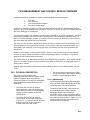
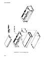
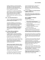
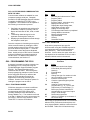
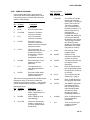
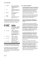
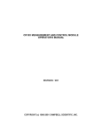
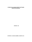
CR10 MEASUREMENT AND CONTROL MODULE
OPERATOR'S MANUAL
REVISION: 3/96
COPYRIGHT (c) 1987-1996 CAMPBELL SCIENTIFIC, INC.
This is a blank page.
CR10 MEASUREMENT AND CONTROL MODULE OVERVIEW
Campbell Scientific Inc. provides four aids to understanding and operating the CR10:
1.
2.
3.
4.
PCTOUR
This Overview
The CR10 Operator's Manual
The CR10 Prompt Sheet
PCTOUR is a computer-guided tour of CR10 operation and the use of the PC208 Datalogger Support
Software. Much of the material in this Overview is covered in PCTOUR. A copy of PCTOUR is included
with every datalogger or PC208 order.
This Overview introduces the concepts required to take advantage of the CR10's capabilities. Hands-on
programming examples start in Section OV5. Working with a CR10 will help the learning process, so
don't just read the examples, do them. If you want to start this minute, go ahead and try the examples,
then come back and read the rest of the Overview.
The sections of the Operator's Manual which should be read to complete a basic understanding of the
CR10 operation are the Programming Sections 1-3, the portions of the data retrieval Sections 4 and 5
appropriate to the method(s) you are using (see OV6), and Section 14 which covers installation and
maintenance.
Section 6 covers details of serial communications. Sections 7 and 8 contain programming examples.
Sections 9-12 have detailed descriptions of each programming instruction, and Section 13 goes into
detail on the CR10 measurement procedures.
The Prompt Sheet is an abbreviated description of the programming instructions. Once familiar with the
CR10, it is possible to program it using only the Prompt Sheet as a reference, consulting the manual if
further detail is needed.
Read the Selected Operating Details and Cautionary Notes at the front of the Manual before using the
CR10.
OV1. PHYSICAL DESCRIPTION
The CR10 is a fully programmable
datalogger/controller in a small, rugged, sealed
module. Programming is very similar to
Campbell Scientific's 21X and CR7 dataloggers.
Some fundamental physical differences are
listed below.
•
The CR10 does not have an integral
keyboard/display. The user accesses the
CR10 with the portable CR10KD Keyboard
Display or with a computer or terminal
(Section OV2).
•
The CR10 does not have an integral
terminal strip. A removable wiring panel
(Figure OV1.1-1) performs this function and
attaches to the two D-type connectors
located at the end of the module.
•
The power supply is external to the CR10.
This gives the user a wide range of options
(Section 14) for powering the CR10.
OV1.1 WIRING PANEL
The CR10 Wiring Panel and CR10 datalogger
make electrical contact through the two D-type
connectors at the (left) end of the CR10.
The Wiring Panel contains a 9-pin Serial I/O
port used when communicating with the
datalogger and provides terminals for
connecting sensor, control, and power leads to
the CR10. It also provides transient protection
and reverse polarity protection. Figure OV1.1-2
shows the panel and the instructions used to
access the various terminals.
OV-1
CR10 OVERVIEW
FIGURE OV1.1-1. CR10 and Wiring Panel
OV-2
CR10 OVERVIEW
FIGURE OV1.1-2. CR10 Wiring Panel/Instruction Access
OV-3
CR10 OVERVIEW
OV1.1.1 ANALOG INPUTS
The terminals labeled 1H to 6L are analog
inputs. These numbers refer to the high and
low inputs to the differential channels 1 through
6. In a differential measurement, the voltage on
the H input is measured with respect to the
voltage on the L input. When making singleended measurements, either the H or L input
may be used as an independent channel to
measure voltage with respect to the CR10
analog ground (AG). The single-ended
channels are numbered sequentially starting
with 1H; e.g., the H and L sides of differential
channel 1 are single-ended channels 1 and 2;
the H and L sides of differential channel 2 are
single-ended channels 3 and 4, etc. (The
single-ended channel numbers do NOT appear
on older wiring panels).
OV1.1.2 SWITCHED EXCITATION OUTPUTS
The terminals labeled E1, E2, and E3 are
precision, switched excitation outputs used to
supply programmable excitation voltages for
resistive bridge measurements. DC or AC
excitation at voltages between -2500 mV and
+2500 mV are user programmable (Section 9).
OV1.1.3 PULSE INPUTS
The terminals labeled P1 and P2 are the pulse
counter inputs for the CR10. They are
programmable for switch closure, high
frequency pulse or low level AC (Section 9,
Instruction 3).
OV1.1.4 DIGITAL I/O PORTS
Terminals C1 through C8 are digital
Input/Output ports. On power-up they are
configured as input ports, commonly used for
reading the status of an external signal. High
and low conditions are: 3V < high < 5.5V; -0.5V
< low < 0.8V.
Configured as outputs the ports allow on/off
control of external devices. A port can be set
high (5V ± 0.1V), set low (<0.1V), toggled or
pulsed (Sections 3, 8.3, and 12).
OV1.1.5 ANALOG GROUND (AG)
The AG terminals are analog grounds, used as
the reference for single-ended measurements
and excitation return.
OV-4
OV1.1.6 12V AND POWER GROUND (G)
TERMINALS
The 12V and power ground (G) terminals are
used to supply 12V DC power to the datalogger.
The extra 12V and G terminals can be used to
connect other devices requiring 12V power.
The G terminals are also used to tie cable
shields to ground, and to provide a ground
reference for pulse counters and binary inputs.
For protection against transient voltage spikes,
power ground should be connected to a good
earth ground (Section 14.3.1).
OV1.1.7 5V OUTPUTS
The two 5V (±0.2%) outputs are commonly
used to power peripherals such as the QD1
Incremental Encoder Interface, AVW1 or AVW4
Vibrating Wire Interface.
The 5V outputs are common with pin 1 on the 9
pin serial connector; 200 mA is the maximum
combined output.
OV1.1.8 SERIAL I/O
The 9 pin serial I/O port contains lines for serial
communication between the CR10 and external
devices such as computers, printers, Storage
Modules, etc. This port does NOT have the
same configuration as the 9 pin serial ports
currently used on many personal computers.
It has a 5VDC power line which is used to power
peripherals such as the SM192 or SM716
Storage Module or the DC112 Phone Modem.
The same 5VDC supply is used for the 5V
outputs on the lower terminal strip. Section 6
contains technical details on serial
communication.
OV1.1.9 SWITCHED 12 VOLT
Wiring panels introduced in March 1994 include
a switched 12 volt output. This can be used to
power sensors or devices requiring an
unregulated 12 volts. The output is limited to
600 mA current.
A control port is used to operate the switch.
Connect a wire from the control port to the
switched 12 volt control port. When the port is
set high, the 12 volts is turned on; when the port
is low, the switched 12 volts is off.
CR10 OVERVIEW
OV1.2 CONNECTING POWER TO THE CR10
The CR10 can be powered by any 12VDC
source. First connect the positive lead from the
power supply to one of the 12V terminals and
then connect the negative lead to one of the
power ground (G) terminals. The Wiring Panel
power connection is reverse polarity protected.
See Section 14 for details on power supply
connections.
CAUTION: The metal surfaces of the
CR10 Wiring Panel, and CR10KD Keyboard
Display are at the same potential as power
ground. To avoid shorting 12 volts to
ground, connect the 12 volt lead first, then
connect the ground lead.
OV2. MEMORY AND PROGRAMMING
CONCEPTS
The CR10 must be programmed before it will
make any measurements. A program consists
of a group of instructions entered into a
program table. The program table is given an
execution interval which determines how
frequently that table is executed. When the
table is executed, the instructions are executed
in sequence from beginning to end. After
executing the table, the CR10 waits the
remainder of the execution interval and then
executes the table again starting at the
beginning.
The interval at which the table is executed
generally determines the interval at which the
sensors are measured. The interval at which
data are stored is separate from how often the
table is executed, and may range from samples
every execution interval to processed
summaries output hourly, daily, or on longer or
irregular intervals.
Figure OV2.1-1 represents the measurement,
processing, and data storage sequence, and
the types of instructions used to accomplish
these tasks.
OV2.1 INTERNAL MEMORY
The CR10 has 64K bytes of Random Access
Memory (RAM), divided into five areas. The
use of the Input, Intermediate, and Final
Storage in the measurement and data
processing sequence is shown in Figure OV2.11. While the total size of these three areas
remains constant, memory may be reallocated
between the areas to accommodate different
measurement and processing needs (*A Mode,
Section 1.5). The size of the 2 additional
memory areas, system and program, are fixed.
The five areas of RAM are:
1. Input Storage - Input Storage holds the
results of measurements or calculations.
The *6 Mode is used to view Input Storage
locations for checking current sensor
readings or calculated values. Input
Storage defaults to 28 locations. Additional
locations can be assigned using the *A
Mode (Section 1.5).
2. Intermediate Storage - Certain Processing
Instructions and most of the Output
Processing Instructions maintain
intermediate results in Intermediate
Storage. Intermediate storage is
automatically accessed by the instructions
and cannot be accessed by the user. The
default allocation is 64 locations. The
number of locations can be changed using
the *A Mode.
3. Final Storage - Final processed values are
stored here for transfer to printer, solid state
Storage Module or for retrieval via
telecommunication links. Values are stored
in Final Storage only by the Output
Processing Instructions and only when the
Output Flag is set in the users program.
Approximately 29,900 locations are
allocated to Final Storage on power up.
This number is reduced if Input or
Intermediate Storage is increased.
4. System Memory - used for overhead tasks
such as compiling programs, transferring
data etc. The user cannot access this
memory.
5. Program Memory - available for user
programs entered in program tables 1 and
2, and Subroutine Table 3.
OV-5
CR10 OVERVIEW
INPUT/OUTPUT
INSTRUCTIONS
Sensors
Control
Specify the conversion of a sensor signal
to a data value and store it in Input
Storage. Programmable entries specify:
(1) the measurement type
(2) the number of channels to measure
(3) the input voltage range
(4) the Input Storage Location
(5) the sensor calibration constants
used to convert the sensor output to
engineering units
I/O Instructions also control analog
outputs and digital control ports.
INPUT STORAGE
PROCESSING INSTRUCTIONS
Holds the results of measurements or
calculations in user specified locations.
The value in a location is written over
each time a new measurement or
calculation stores data to the locations.
Perform calculations with values in Input
Storage. Results are returned to Input
Storage. Arithmetic, transcendental and
polynomial functions are included.
OUTPUT PROCESSING
INSTRUCTIONS
INTERMEDIATE STORAGE
Perform calculations over time on the
values updated in Input Storage.
Summaries for Final Storage are
generated when a Program Control
Instruction sets the Output Flag in
response to time or events. Results
may be redirected to Input Storage for
further processing. Examples include
sums, averages, max/min, standard
deviation, histograms, etc.
Provides temporary storage for
intermediate calculations required by the
OUTPUT PROCESSING INSTRUCTIONS;
for example, sums, cross products,
comparative values, etc.
Output Flag set high
FINAL STORAGE
Final results from OUTPUT
PROCESSING INSTRUCTIONS are
stored here for on-line or interrogated
transfer to external devices (Figure
OV5.1-1). The newest data are stored
over the oldest in a ring memory.
FIGURE OV2.1-1. Instruction Types and Storage Areas
OV-6
CR10 OVERVIEW
OV2.2 CR10 INSTRUCTION TYPES
Figure OV2.1-1 illustrates the use of three
different instruction types which act on data.
The fourth type, Program Control, is used to
control output times and vary program
execution. Instructions are identified by
numbers.
1. INPUT/OUTPUT INSTRUCTIONS (1-28,
101-104, Section 9) control the terminal
strip inputs and outputs (the sensor is the
source, Figure OV1.1-2), storing the results
in Input Storage (destination). Multiplier
and offset parameters allow conversion of
linear signals into engineering units. The
Digital I/O Ports are also addressed with I/O
Instructions.
2. PROCESSING INSTRUCTIONS (30-66,
Section 10) perform numerical operations
on values located in Input Storage (source)
and store the results back in Input Storage
(destination). These instructions can be
used to develop high level algorithms to
process measurements prior to Output
Processing.
3. OUTPUT PROCESSING INSTRUCTIONS
(69-82, Section 11) are the only
instructions which store data in Final
Storage (destination). Input Storage
(source) values are processed over time to
obtain averages, maxima, minima, etc.
There are two types of processing done by
Output Instructions: Intermediate and
Final.
Intermediate processing normally takes
place each time the instruction is executed.
For example, when the Average Instruction
is executed, it adds the values from the
input locations being averaged to running
totals in Intermediate Storage. It also keeps
track of the number of samples.
Final processing occurs only when the
Output Flag is high. The Output Processing
Instructions check the Output Flag. If the
flag is high, final values are calculated and
output. With the Average, the totals are
divided by the number of samples and the
resulting averages sent to Final Storage.
Intermediate locations are zeroed and the
process starts over. The Output Flag, Flag
0, is set high by a Program Control
Instruction which must precede the Output
Processing Instructions in the user entered
program.
4. PROGRAM CONTROL INSTRUCTIONS
(83-98, Section 12) are used for logic
decisions and conditional statements. They
can set flags, compare values or times,
execute loops, call subroutines, conditionally
execute portions of the program, etc.
OV2.3 PROGRAM TABLES, EXECUTION
INTERVAL AND OUTPUT INTERVALS
Programs are entered in Tables 1 and 2.
Subroutines, called from Tables 1 and 2, are
entered in Subroutine Table 3. The size of each
table is flexible, limited only by the total amount
of program memory. If Table 1 is the only table
programmed, the entire program memory is
available for Table 1.
Table 1 and Table 2 have independent
execution intervals, entered in units of seconds
with an allowable range of 1/64 to 8191
seconds. Subroutine Table 3 has no execution
interval; subroutines are only executed when
called from Table 1 or 2.
OV2.3.1 THE EXECUTION INTERVAL
The execution interval specifies how often the
program in the table is executed, which is
usually determined by how often the sensors
are to be measured. Unless two different
measurement rates are needed, use only one
table. A program table is executed sequentially
starting with the first instruction in the table and
proceeding to the end of the table.
OV-7
CR10 OVERVIEW
Table 1.
Execute every x sec.
0.0156 < x < 8191
Instructions are executed
sequentially in the order they
are entered in the table. One
complete pass through the
table is made each execution
interval unless program
control instructions are used
to loop or branch execution.
Normal Order:
MEASURE
PROCESS
CHECK OUTPUT COND.
OUTPUT PROCESSING
Table 2.
Execute every y sec.
0.0156 < y < 8191
Table 2 is used if there is a
need to measure and
process data on a separate
interval from that in Table 1.
Table 3.
Subroutines
A subroutine is executed
only when called from Table
1 or 2.
Subroutine Label
Instructions
End
Subroutine Label
Instructions
End
Subroutine Label
Instructions
End
FIGURE OV2.3-1. Program and Subroutine Tables
Each instruction in the table requires a finite
time to execute. If the execution interval is less
than the time required to process the table, an
execution interval overrun occurs; the CR10
finishes processing the table and waits for the
next execution interval before initiating the
table. When an overrun occurs, decimal points
are shown on either side of the G on the display
in the LOG mode (*0). Overruns and table
priority are discussed in Section 1.1.
OV2.3.2. THE OUTPUT INTERVAL
The interval at which output occurs is
independent from the execution interval, other
than the fact that it must occur when the table is
executed (e.g., a table cannot have a 10 minute
execution interval and output every 15 minutes).
A single program table can have many different
output intervals and conditions, each with a
unique data set (Output Array). Program
Control Instructions are used to set the Output
Flag. The Output Processing Instructions which
follow the instruction setting the Output Flag
determine the data output and its sequence.
Each additional Output Array is created by
another Program Control Instruction checking a
output condition, followed by Output Processing
Instructions defining the data set to output.
OV3. COMMUNICATING WITH CR10
An external device must be connected to the
CR10's Serial I/O port to communicate with the
CR10. This may be either Campbell Scientific's
portable CR10KD Keyboard Display or a
computer/terminal.
The CR10KD is powered by the CR10 and
connects directly to the serial port via the SC12
cable (supplied with the CR10KD). No
interfacing software is required.
To communicate with any device other than the
CR10KD, the CR10 enters its Telecommunications Mode and responds only to valid
telecommunications commands. Within the
Telecommunications Mode, there are 2 "states";
the Telecommunications Command state and the
Remote Keyboard state. Communication is
established in the Telecommunications command
state. One of the commands is to enter the
Remote Keyboard state.
The Remote Keyboard state allows the
keyboard of the computer/terminal to act like
the CR10KD keyboard. Various datalogger
modes may be entered, including the mode in
which programs may be keyed in to the CR10
from the computer/terminal.
Campbell Scientific's PC208 Datalogger
Support Software facilitates the use of IBM
PC/XT/AT/PS-2's and compatibles for
communicating with the CR10. This package
contains a program editor (EDLOG), a terminal
OV-8
CR10 OVERVIEW
emulator (GraphTerm), telecommunications
(TELCOM), a data reduction program (SPLIT),
and programs to retrieve data from both
generations of Campbell Scientific's Storage
Modules (SMREAD and SMCOM).
returns as described above or select the "C"
option to "Call" the station (see PC208
Operator's Manual). Once the link is active,
issue the "7H" command to enter the Remote
Keyboard State.
To participate in the programming examples
(Section OV5) you must communicate with the
CR10. Read Section OV3.1 if the CR10KD is
being used, Section OV3.2 if the PC208
software is being used, or Section 3.3 and
Section 5 if some other computer or terminal is
being used.
OV3.3 ASCII TERMINAL OR COMPUTER WITH
TERMINAL EMULATOR
OV3.1 CR10 KEYBOARD/DISPLAY
The SC12 cable (supplied with the CR10KD) is
used to connect the Keyboard/Display to the 9
pin Serial I/O port on the CR10.
If the Keyboard/Display is connected to the
CR10 prior to being powered up, the "HELLO"
message is displayed while the CR10 checks
memory. The size of the usable system
memory is then displayed (96 for 96K bytes of
memory). When the CR10KD is plugged in
after the CR10 has powered up, the display is
meaningless until "*" is pressed to enter a
mode.
OV3.2 USING THE PC208 TERMINAL
EMULATOR (GRAPHTERM)
Devices which can be used to communicate
with the CR10 include standard ASCII terminals
and computers programmed to function as a
terminal emulator.
OV3.3.1 COMPUTER/TERMINAL
REQUIREMENTS
The basic requirements are:
1. There must be an asynchronous serial port
to transmit and receive characters.
2. Communication protocol must be matched
for the two devices.
3. The proper cable/interface must be used
between the serial ports.
4. A computer must be programmed to
function as a terminal.
While the connection between the
computer/terminal and the CR10 may be via
modem (phone, RF, or short haul), the most
frequently used device for a short connection is
the SC32A Optically Isolated RS232 Interface.
For IBM compatible computers, the PC208
software contains a terminal emulator program
called GraphTerm. When using GraphTerm,
the baud rate, port, and modem types are
specified and stored in a file for future use.
Most computer/terminal devices require RS232
input logic levels of -5V for logic low and +5V for
logic high. Logic levels from the CR10's serial
I/O port are 0V for logic low and +5V for logic
high.
The simplest and most common interface is the
SC32A Optically Isolated RS232 Interface. The
SC32A converts and optically isolates the
voltages passing between the CR10 and the
external terminal device.
The SC32A converts and optically isolates the
voltages passing between the CR10 and the
external terminal device. The SC32A is
configured as Data Communications Equipment
(DCE) for direct connection to Data Terminal
Equipment (DTE) which includes most
computers and terminals.
The SC12 Two Peripheral cable which comes
with the SC32A is used to connect the serial I/O
port of the CR10 to the 9 pin port of the SC32A
labeled "Datalogger". Connect the
"Terminal/Printer" port of the SC32A to the
serial port of the computer with a straight 25 pin
cable or, if the computer has a 9 pin serial port,
a standard 9 to 25 pin adapter cable.
To establish the communication link between
the computer and the CR10, the user may
either select the T option and send carriage
The SC12 Two Peripheral cable which comes
with the SC32A is used to connect the serial I/O
port of the CR10 to the 9 pin port of the SC32A
labeled "Datalogger". Connect the
"Terminal/Printer" port of the SC32A to the
serial port of the terminal with a user supplied
straight cable with the proper connectors
(Campbell Scientific SC25PS or equivalent for a
25 pin serial port configured DTE).
OV-9
CR10 OVERVIEW
OV3.3.2 ESTABLISHING COMMUNICATION
WITH THE CR10
Communication software is available for most
computers having a serial port. Campbell
Scientific's PC208 Datalogger Support Software
is available for IBM PC/XT/AT/PS-2's and
compatibles. The software must be capable of
the following communication protocol:
1. Configuring an asynchronous serial port for
8 Data Bits, 1 Stop Bit, no Parity, and Full
Duplex at baud rates of 300, 1200, or 9600
baud.
2. Transmitting characters typed on the
keyboard out through the serial port.
3. Displaying characters/data received through
the computer's serial port.
Once the computer is functioning as a terminal,
initiate communications by sending the CR10
several carriage returns for the CR10 to match
the baud rate and respond with "*". Enter the
7H command to enter the Remote Keyboard
State. At this point, the CR10 can be controlled
using the Keyboard Commands described in
Section OV4. For additional information on
communications, see Section 6.7.
OV4. PROGRAMMING THE CR10
A program is created by entering it directly into
the datalogger or on a computer using the
PC208 Datalogger Support Software program
EDLOG. This manual describes direct
interaction with the CR10. Work through the
direct programming examples in this overview
before using EDLOG and you will have the
basics of CR10 operation as well as an
appreciation for the help provided by the
software. Section OV4.5 describes options for
loading the program into the CR10.
OV4.1 FUNCTIONAL MODES
CR10/User interaction is broken into different
functional MODES (e.g., programming the
measurements and output, setting time,
manually initiating a block data transfer to
Storage Module, etc.). The modes are referred
to as Star (*) Modes since they are accessed by
first keying *, then the mode number or letter.
Table OV4.1-1 lists the CR10 Modes.
OV-10
TABLE OV4.1-1. * Mode Summary
Key
Mode
*0
*1
*2
*3
*5
*6
LOG data and indicate active Tables
Program Table 1
Program Table 2
Program Table 3, subroutines only
Display/set real time clock
Display/alter Input Storage data,
toggle flags or control ports.
Display Final Storage data
Final Storage data transfer to peripheral
Storage Module commands
Memory allocation/reset
Signature/status
Security
Save/load Program
*7
*8
*9
*A
*B
*C
*D
OV4.2 KEY DEFINITION
Keys and key sequences have specific
functions when using the CR10KD keyboard or
a computer/terminal in the remote keyboard
state (Section 5). Table OV4-2 lists these
functions. In some cases, the exact action of a
key depends on the mode the CR10 is in and is
described with the mode in the manual.
TABLE OV4.2-1. Key Description/Editing
Functions
Key
Action
0-9
*
Key numeric entries into display
Enter Mode (followed by Mode
Number)
Enter/Advance
Back up
Change the sign of a number or index
an input location to loop counter
Enter the decimal point
Clear the rightmost digit keyed into
the display
Advance to next instruction in
program table (*1, *2, *3) or to next
Output Array in Final Storage (*7)
Back up to previous instruction in
program table or to previous Output
Array in Final Storage
Delete entire instruction
(then A or CR) Back up to the start of
the current array.
A
B
C
D
#
#A
#B
#D
#0
When using a computer/terminal to communicate
with the CR10 (Telecommunications) there are
some keys available in addition to those found on
the CR10KD. Table OV4.2-2 lists these keys.
CR10 OVERVIEW
TABLE OV4.2-2. Additional Keys Allowed in
Telecommunications
Key
Action
CR
:
S or ^S
Change Sign, Index (same as C)
Enter/advance (same as A)
Colon (used in setting time)
Stops transmission of data (10
second time-out; any character
restarts)
Aborts transmission of Data
C or ^C
OV4.3 PROGRAMMING SEQUENCE
In routine applications, the CR10 measures
sensor output signals, processes the
measurements over some time interval and
stores the processed results. A generalized
programming sequence is:
1. Enter the execution interval. In most cases,
the execution interval is determined by the
desired sensor scan rate.
2. Enter the Input/Output instructions required
to measure the sensors.
3. If processing in addition to that provided by
the Output Processing Instructions (step 5)
is required, enter the appropriate
Processing Instructions.
4. Enter the Program Control Instruction to
test the output condition and set the Output
Flag when the condition is met. For
example, use
Instruction 92 to output based on time.
Instruction 86 to output every execution
interval.
Instruction 88 or 89 to output based on a
comparison of values in input locations.
This instruction must precede the Output
Processing Instructions which store data in
Final Storage. Instructions are described in
Sections 9 through 12.
5. Enter the Output Processing Instructions to
store processed data in Final Storage. The
order in which data are stored is determined
by the order of the Output Processing
Instructions in the table.
6. Repeat steps 4 through 6 for additional
outputs on different intervals or conditions.
NOTE: The program must be executed for
output to occur. Therefore, the interval at
which the Output Flag is set must be evenly
divisible by the execution interval. For
example, with a 2 minute execution interval
and a 5 minute output interval, the program
will only be executed on the even multiples
of the 5 minute intervals, not on the odd.
Data will be output every 10 minutes
instead of every 5 minutes.
Execution intervals and output intervals set with
Instruction 92 are synchronized with real time
starting at midnight.
OV4.4 INSTRUCTION FORMAT
Instructions are identified by an instruction
number. Each instruction has a number of
parameters that give the CR10 the information it
needs to execute the instruction.
The CR10 Prompt Sheet has the instruction
numbers in red, with the parameters briefly
listed in columns following the description.
Some parameters are footnoted with further
description under the "Instruction Option Codes"
heading.
For example, Instruction 73 stores the
maximum value that occurred in an Input
Storage location over the output interval. The
instruction has three parameters (1)
REPetitionS, the number of sequential Input
Storage locations on which to find maxima, (2)
TIME, an option of storing the time of
occurrence with the maximum value, and (3)
LOC the first Input Storage location operated on
by the Maximum Instruction. The codes for the
TIME parameter are listed in the "Instruction
Option Codes".
The repetitions parameter specifies how many
times an instruction's function is to be repeated.
For example, four 107 thermistor probes may be
measured with a single Instruction 11, Temp107, with four repetitions. Parameter 2 specifies
the input channel of the first thermistor (the
probes must be connected to sequential
channels). Parameter 4 specifies the Input
Storage location in which to store measurements
from the first thermistor. If location 5 were used
and the first probe was on channel 1, the
OV-11
CR10 OVERVIEW
temperature of the thermistor on channel 1
would be stored in input location 5, the
temperature from channel 2 in input location 6,
etc.
Detailed descriptions of the instructions are
given in Sections 9-12. Entering an instruction
into a program table is described in OV5.
Module. Up to 8 programs can be stored in the
Storage Module, the programs may be assigned
any of the numbers 1-8. If the Storage Module
is connected when the CR10 is powered-up the
CR10 will automatically load program number 8,
provided that a program 8 is loaded in the
Storage Module (Section 1.8).
OV5. PROGRAMMING EXAMPLES
OV4.5 ENTERING A PROGRAM
Programs are entered into the CR10 in one of
three ways:
1. Keyed in using the CR10 keyboard.
2. Loaded from a pre-recorded listing using
the *D Mode. There are 3 types of
storage/input:
a. Stored on disk/sent from computer
(PC208 software GraphTerm and
EDLOG).
b. Stored/loaded from SM192/716 Storage
Module.
3. Loaded from internal PROM (special software) or Storage Module upon power-up.
A program is created by keying it directly into
the datalogger as described in Section OV5, or
on a PC using the PC208 Datalogger Support
Software.
EDLOG and GraphTerm are PC208 Software
programs used to develop and send programs to
Campbell Scientific dataloggers. EDLOG is an
editor for writing and documenting programs for
Campbell Scientific dataloggers. Program files
developed with EDLOG can be downloaded directly
to the CR10 using GraphTerm. GraphTerm
supports communication via direct wire, telephone,
or Radio Frequency (RF).
Programs on disk can be copied to a Storage
Module with SMCOM. Using the *D Mode to
save or load a program from a Storage Module
is described in Section 1.8.
We will start with a simple programming
example. There is a brief explanation of each
step to help you follow the logic. When the
example uses an instruction, find it on the
Prompt Sheet and follow through the description
of the parameters. Using the Prompt Sheet
while going through these examples will help
you become familiar with its format. Sections 912 have more detailed descriptions of the
instructions.
Connect the CR10 to either a CR10KD
Keyboard/Display or a terminal (Section OV2).
With the Wiring Panel connected to the CR10,
hook up the power leads as described in
Section OV1.2. If using a terminal, use the 7H
command to get into the Remote Keyboard
State (Sections 5.2). The programming steps in
the following examples use the keystrokes
possible on the keyboard/display. With a
terminal, some responses will be slightly
different.
If the CR10KD is connected to the CR10 when
it is powered up, the display will show:
Display
HELLO
after a few seconds delay
:96
It is possible (with special software) to create a
PROM (Programmable Read Only Memory) that
contains a datalogger program. With this
PROM installed in the datalogger, the program
will automatically be loaded and run when the
datalogger is powered-up, requiring only that
the clock be set.
The program on power up function can be
achieved by using a SM192/716 Storage
OV-12
Explanation
On power-up, the CR10
displays "HELLO" while it
checks the memory (this
display occurs only with the
CR10KD).
The size of the machine's total
memory (RAM plus 32 K of
ROM), in this case 96K
CR10 OVERVIEW
OV5.1 SAMPLE PROGRAM 1
In this example the CR10 is programmed to
read its own internal temperature (using a built
in thermistor) every 5 seconds and to send the
results to Final Storage.
Display Will Show:
Key (ID:Data)
Display Will Show:
Key (ID:Data)
Wait a few seconds:
01:21.423
The CR10 has read the
sensor and stored the
result again. The internal
temp is now 21.423 oC.
The value is updated
every 5 seconds when
the table is executed. At
this point the CR10 is
measuring the
temperature every 5
seconds and sending the
value to Input Storage.
No data are being saved.
The next step is to have
the CR10 send each
reading to Final Storage.
(Remember, the Output
Flag must be set first.)
*1
01:00
Exit *6 Mode. Enter
program table 1.
2A
02:P00
Advance to 2nd
instruction location (this
is where we left off).
Explanation
*
00:00
Enter mode.
1
01:00
Enter Program Table 1.
A
01:0.0000
Advance to execution
interval (In seconds)
5
01:5
Key in an execution
interval of 5 seconds.
A
01:P00
Enter the 5 second
execution interval and
advance to the first program
instruction location.
17
01:P17
Key in Instruction 17
which directs the CR10 to
measure the internal
temperature in degrees
C. This is an
Input/Output Instruction.
Explanation
A
01:0000
Enter Instruction 17 and
advance to the first
parameter.
86
02:P86
This is the DO instruction
(a Program Control
Instruction).
1
01:1
The input location to
store the measurement,
location 1.
A
01:00
A
02:P00
Enter the location # and
advance to the second
program instruction.
Enter 86 and advance to
the first parameter (which
will specify the command
to execute).
10
01:10
This command sets the
Output Flag. (Flag 0)
A
03:P00
Enter 10 and advance to
third program instruction.
70
03:P70
The SAMPLE instruction.
It directs the CR10 to
take a reading from an
Input Storage location
and send it to Final
Storage (an Output
Processing Instruction).
A
01:0000
Enter 70 and advance to
the first parameter
(repetitions).
1
01:1
There is only one input
location to sample;
repetitions = 1.
The CR10 is now programmed to read the internal
temperature every 5 seconds and place the
reading in Input Storage Location 1. The program
can be compiled and the temperature displayed.
Display Will Show:
Key (ID:Data)
Explanation
*0
LOG 1
Exit Table 1, enter *0
Mode, compile table and
begin logging.
*6
06:0000
Enter *6 Mode (to view
Input Storage).
A
01:21.234
Advance to first storage
location. Panel temp. is
21.234oC (display shows
actual temp.).
OV-13
CR10 OVERVIEW
A
02:0000
Enter 1 and advance to
second parameter (Input
Storage location to
sample).
1
02:1
Input Storage Location 1,
where the temperature is
stored.
A
04:P00
Enter 1 and advance to
fourth program
instruction.
*
00:00
Exit Table 1.
0
LOG 1
Enter *0 Mode, compile
program, log data.
The CR10 is now programmed to measure the
internal temperature every 5 seconds and send
each reading to Final Storage. Values in Final
Storage can be viewed using the *7 Mode.
Display Will Show:
Key (ID:Data)
Explanation
*7
07: 13.000
Enter *7 Mode. The Data
Storage Pointer (DSP) is
at Location 13 (in this
example).
A
01: 0102
Advance to the first
value, the Output Array
ID. 102 indicates the
Output Flag was set by
the second instruction in
Program Table 1.
A
02: 21.23
Advance to the first
stored temperature.
A
01: 0102
Advance to the next
output array. Same
Output Array ID.
A
02: 21.42
Advance to 2nd stored
temp, 21.42 deg. C.
There are no date and time tags on the data.
They must be put there with Output Instruction
77. Instruction 77 is used in the next example.
If a terminal is used to communicate with the
CR10, Telecommunications Commands
(Section 5) can be used to view entire Output
Arrays (in this case the ID and temperature) at
the same time.
OV-14
OV5.2 SAMPLE PROGRAM 2
This second example is more representative of a
real-life data collection situation. Once again the
internal temperature is measured, but it is used
as a reference temperature for the differential
voltage measurement of a type T (copperconstantan) thermocouple; the CR10 should
have arrived with a short type T thermocouple
connected to differential channel 5.
When using a type T thermocouple, the copper
lead (blue) is connected to the high input of the
differential channel, and the constantan lead
(red) is connected to the low input.
A thermocouple produces a voltage that is
proportional to the difference in temperature
between the measurement and the reference
junctions.
To make a thermocouple (TC) temperature
measurement, the temperature of the reference
junction (in this example, the approximate panel
temperature) must be measured. The CR10
takes the reference temperature, converts it to
the equivalent TC voltage relative to 0oC, adds
the measured TC voltage, and converts the
sum to temperature through a polynomial fit to
the TC output curve (Section 13.4).
The internal temperature of the CR10 is not a
suitable reference temperature for precision
thermocouple measurements. It is used here
for the purpose of training only. To make
thermocouple measurements with the CR10,
purchase the Campbell Scientific Thermocouple
Reference, Model CR10TCR (Section 13.4) and
make the reference temperature measurement
with Instruction 11.
Instruction 14 directs the CR10 to make a
differential TC temperature measurement. The
first parameter in Instruction 14 is the number of
times to repeat the measurement. Enter 1,
because in this example there is only one
thermocouple. If there were more than 1 TC,
they could be wired to sequential channels, and
the number of thermocouples entered for
repetitions. The CR10 would automatically
advance through the channels sequentially and
measure all of the thermocouples.
CR10 OVERVIEW
Parameter 2 is the voltage range to use when
making the measurement. The output of a type
T thermocouple is approximately 40 microvolts
per degree C difference in temperature between
the two junctions. The ±2.5 mV scale will
provide a range of +2500/40 = +62.5 oC (i.e.,
this scale will not overrange as long as the
measuring junction is within 62.5 oC of the
panel temperature). The resolution of the ±2.5
mV range is 0.33 µV or 0.008 oC.
Parameter 3 is the analog input channel on
which to make the first, and in this case only,
measurement.
Parameter 4 is the code for the type of
thermocouple used. This information is located
on the Prompt Sheet or in the description of
Instruction 14 in Section 9. The code for a type
T (copper-constantan) thermocouple is 1.
Parameter 5 is the Input Storage location in
which the reference temperature is stored.
Parameter 6 is the Input Storage location in
which to store the measurement (or the first
measurement; e.g., if there are 5 repetitions
and the first measurement is stored in location
3, the final measurement will be stored in
location 7). Parameters 7 and 8 are the
multiplier and offset. A multiplier of 1 and an
offset of 0 outputs the reading in degrees C. A
multiplier of 1.8 and an offset of 32 converts the
reading to degrees F.
In this example, the sensor is measured once a
minute, and the day, time, and average
temperature are output every hour. Once a day
the day, time, maximum and minimum
temperatures and the times they occur will be
output.
Final Storage data will be sent to Storage
Module. Remember, all on-line data output to a
peripheral device is accomplished with
Instruction 96 (Sections 4.1 and 12).
The first example described program entry one
keystroke at a time. This example does not
show the "A" key. Remember, "A" is used to
enter and/or advance (i.e., between each line in
the example below). This format is similar to
the format used in EDLOG.
It's a good idea to have both the manual and the
Prompt Sheet handy when going through this
example. You can find the program instructions
and parameters on the Prompt Sheet and can
read their complete definitions in the manual.
To obtain daily output, the If Time instruction is
again used to set the Output Flag and is
followed by the Output Instructions to store time
and the daily maximum and minimum
temperatures and the time each occurs.
Any Program Control Instruction which is used
to set the Output Flag high will set it low if the
conditions are not met for setting it high.
Instruction 92 above sets the Output Flag high
every hour. The Output Instructions which
follow do not output every hour because they
are preceded by another Instruction 92 which
sets the Output Flag high at midnight (and sets
it low at any other time). This is a unique
feature of Flag 0. The Output Flag is set low at
the start of each table (Section 3.7).
OV5.3 EDITING AN EXISTING PROGRAM
When editing an existing program in the CR10,
entering a new instruction inserts the
instruction; entering a new parameter replaces
the previous value.
To insert an instruction, enter the program table
and advance to the position where the
instruction is to be inserted (i.e., P in the data
portion of the display) key in the instruction
number, and then key A. The new instruction
will be inserted at that point in the table,
advance through and enter the parameters.
The instruction that was at that point and all
instructions following it will be pushed down to
follow the inserted instruction.
An instruction is deleted by advancing to the
instruction number (P in display) and keying #D
(Table 4.2-1).
To change the value entered for a parameter,
advance to the parameter and key in the correct
value then press A. Note that the new value is
not entered until A is keyed.
OV-15
CR10 OVERVIEW
SAMPLE PROGRAM 2
Instruction #
(Loc:Entry)
Parameter
(Par#:Entry)
Description
*1
Enter Program Table 1
01:60
60 second (1 minute) execution interval
Key "#D" until
is displayed
01:P00
01:P17
01:1
02:P14
(differential)
Measure internal temperature
Store temp in Location 1
Measure thermocouple temperature
01:1
02:1
03:5
04:1
05:1
06:2
07:1
08:0
Instruction #
(Loc.:Entry)
Erase previous Program before
continuing.
Parameter
Par.#:Entry)
03:P92
01:0
02:60
03:10
1 repetition
Range code (2.5 mV, slow)
Input channel of TC
TC type: copper-constantan
Reference temp is stored in Location 1
Store TC temp in Location 2
Multiplier of 1
No offset
Description
If Time instruction
0 minutes into the interval
60 minute interval
Set Output Flag 0
The CR10 is programmed to measure the thermocouple temperature every sixty seconds. The
If Time instruction sets the Output Flag at the beginning of every hour. Next, the Output
Instructions for time and average are added.
04:P77
01:110
05:P71
01:1
02:2
Instruction #
(Loc.:Entry)
Parameter
(Par.#:Entry)
06:P92
Average instruction
one repetition
Location 2 - source of TC temps. to be
averaged
Description
01:0
02:1440
03:10
If Time instruction
0 minutes into the interval
1440 minute interval (24 hrs.)
Set Output Flag 0
01:100
Output Time instruction
Store Julian day
01:1
02:10
03:2
Maximize instruction
One repetition
Output time of daily maximum in hours and minutes
Data source is Input Storage Location 2.
07: P77
08: P73
OV-16
Output Time instruction
Store Julian day, hour, and minute
CR10 OVERVIEW
Instruction #
(Loc.:Entry)
Parameter
(Par.#:Entry)
09: P74
01:1
02:10
03:2
Description
Minimize instruction
One repetition
Output the time of the daily minimum in hours
and minutes
Data source is Input Storage Location 2.
The program to make the measurements and to send the desired data to Final Storage has
been entered. At this point, Instruction 96 is entered to enable data transfer from Final Storage
to Storage Module.
10:P96
1:71
Activate Serial Data Output.
Output Final Storage data to Storage Module.
The program is complete. The clock must now be set so that the date and time tags are correct.
(Here the example reverts back to the key by key format.)
Key
Display
Explanation
*5
00:21:32
Enter *5 Mode. Clock running but not set correctly.
A
05:00
Advance to location for year.
86
05:86
Key in year (1986).
A
05:0000
Enter and advance to location for Julian day.
197
05:197
Key in Julian day.
A
05:0021
Enter and advance to location for hours and minutes (24 hr. time).
1324
05:1324
Key in hrs.:min. (1:24 PM in this example).
A
:13:24:01
Clock set and running.
*0
LOG 1
Exit *5, compile Table 1, commence logging data.
OV6. DATA RETRIEVAL OPTIONS
There are several options for data storage and
retrieval. These options are covered in detail in
Sections 2, 4, and 5. Figure OV6.1-1
summarizes the various possible methods.
Regardless of the method used, there are three
general approaches to retrieving data from a
datalogger.
1) On-line output of Final Storage data to a
peripheral storage device. On a regular
schedule, that storage device is either
"milked" of its data or is brought back to the
office/lab where the data is transferred to
the computer. In the latter case, a "fresh"
storage device is usually left in the field
when the full one is taken so that data
collection can continue uninterrupted.
2) Bring a storage device to the datalogger
and milk all the data that has accumulated
in Final Storage since the last visit.
3) Retrieve the data over some form of
telecommunications link, whether it be RF,
telephone, short haul modem, or satellite.
This can be performed under program
control or by regularly scheduled polling of
the dataloggers. Campbell Scientific's
TELCOM program automates this process
for IBM PC/XT/AT/PS-2's and compatibles.
Regardless of which method is used, the
retrieval of data from the datalogger does NOT
erase those data from Final Storage. The data
remain in the ring memory until:
They are written over by new data (Section 2.1)
Memory is reallocated (Section 1.5)
The power to the datalogger is turned off.
Table OV6.1-1 lists the instructions used with
the various methods of data retrieval.
OV-17
CR10 OVERVIEW
TABLE OV6.1-1. Data Retrieval Methods and Related Instructions
Storage
Module
Inst. 96,
*8
*9
Printer, other
Serial Device
Inst. 96,
*8
Inst. 98,
Telecommunications
(RF, Phone, Short Haul, SC32A)
Inst. 97
(Telecommunications Commands)
TABLE OV6.1-2. Data Retrieval Sections in Manual
Instruction or Mode
96
Instr. 97
*8
*9
Telecommunications
OV-18
Section in Manual
4.1, 12
12
4.2
4.5
5
CR10 OVERVIEW
FIGURE OV6.1-1. Data Retrieval Hardware Options
OV-19
CR10 OVERVIEW
OV7. SPECIFICATIONS
OV-20