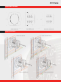
1
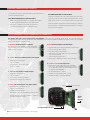
www.electroind.com ® Shark® 200 Meter/Transducer Shark® 200T Transducer Only From Simple to Sophisticated Industry Leading Performance • Simple Multifunction Meter: V-Switch™ Key 1 • Highly Accurate Metering Technology • Historical Data-logging: V-Switch™ Key 2 • Expandable I/O with 100BaseT Ethernet • Advanced Power Quality Waveform Recorder: V-Switch™ Keys 5 or 6 • V-Switch™ Technology Upgrade • Extensive Data Logging • Power Quality Recording Electro Industries/GaugeTech The Leader in Power Monitoring and Control • Up to 512 Samples/Cycle HIGH PERFORMANCE WAVEFORM RECORDING Basic Features Summary • 0.2% Class Revenue Certifiable Energy and Demand Metering • Meets ANSI C12.20 and IEC 687 (0.2% Class) • Multifunction Measurement • 3 Line .56" LED display • % of Load Bar for Analog Perception • Standard RS485 (Modbus and DNP 3.0) • IrDA Port for PDA Read • Ultra-Compact • Fits both ANSI and DIN Cutouts APPLICATIONS Advanced Features Summary • High Performance Waveform Recorder • Up to 4 Megabytes Flash for Historical Data Logging & PQ Recording • Extremely Configurable Field Upgradable I/O • 100BaseT Ethernet – Rapid Response™ Technology • V-Switch™ Technology • Utility Metering • Commercial Metering • Substations • Industrial Metering • Power Generation • Campus Metering • Submetering • Analog Meter Replacement • Power Quality Studies • Disturbance Recording • Load Studies • Voltage Recording ACCURACY AND UPGRADE SWITCHES Electro Industries introduces a new standard in panel mounted power metering. The Shark® 200 metering system is an ultra-compact power metering device providing industry leading revenue metering functionality combined with advanced data-logging, power quality, communication and I/O traditionally found only in high performance ACCURACY Measured Parameters Accuracy % Display Range Voltage L-N 0.1% 0-9999 Scalable V or kV Voltage L-L 0.2% 0-9999 V or kV Scalable Current 0.1% 0-9999 Amps or kAmps +/- Watts 0.2% 0-9999 Watts, kWatts, MWatts +/-Wh 0.2% 5 to 8 Digits Programmable +/-VARs 0.2% 0-9999 VARs, kVARs, MVARs The Shark® 200 meter is equipped with EIG’s exclusive V-Switch™ +/-VARh 0.2% 5 to 8 Digits Programmable technology. This technology allows users to upgrade and add VA 0.2% 0-9999 VA, kVA, MVA features by using communication commands as needed, even VAh 0.2% 5 to 8 Digits Programmable after the meter is installed. PF 0.2% +/- 0.5 to 1.0 V-Switches Include the Following Features: Frequency +/- 0.03 Hz 45 to 65 Hz %THD +/- 2.0% 1 to 99.99% % Load Bar +/- 1 Segment (0.005 to 6) A and high cost systems. This product is designed to incorporate advanced features in a cost effective, small package for large scale, low cost deployment within an electrical distribution system. V-Switch™ Technology Feature V1 Multifunction Measurement with I/O Expansion PP PP PP P PP P P PP P P P PP P P 2 Megabytes Data-Logging 3 Megabytes Data-Logging 4 Megabytes Data-Logging Harmonic Analysis Limit and Control Functions 64 Samples per Cycle Waveform Recorder 512 Samples per Cycle Waveform Recorder V2 V3 V4 V5 V6 Note: Applies to 3 element WYE and 2 element Delta connections. See full accuracy specifications in Shark® 200 Meter User Manual. Neutral current 2% accuracy. Traceable Watt-Hour Test Pulse for Accuracy Verification The Shark® 200 device is a traceable revenue meter. It contains a utility grade test pulse allowing power providers to verify and confirm that the meter is performing to its rated accuracy. This is an essential feature required of all billing grade meters. • Utility Block and Rolling Average Demand • Historical Load Profiling 2 SHARK®200 METER EXTENSIVE DATA-LOGGING CAPABILITY (V2 and Higher) The Shark®200 meter offers the capability of having 2 I/O Change Log Megabytes of data-logging to be used for historical trends, limit · Provides a Time Stamped Log of any Relay Output · Provides a Time Stamped Log of Input Status Changes · 2048 Events Available alarms, I/O changes and sequence of events. The unit has a real-time clock that allows for time stamping of all the data in the instrument when log events are created. Limit/Alarm Log Historical Logs · 3 Assignable Historical Logs · Independently Program Trending Profiles · Up to 64 Parameters per Log System Events Log · Provides Magnitude and Duration of an Event · Includes Time Stamps and Alarm Value · 2048 Events Available Alarm Log To protect critical billing information, the meter records and logs Limits Alarms and Control Capability (V4 Option) the following with a time stamp: · Demand Resets · Password Requests · System Startup · Any measured parameter Energy Resets · Up to 16 Limits · Log Resets · Voltage Imbalance · Log Reads · Current Imbalance Programmable Settings Changes · Based on % of full scale settings · · Limit Events Historical Trending Limit Set Up HIGH PERFORMANCE POWER QUALITY ANALYSIS (V5 AND V6) Simultaneous Voltage and Current Waveform Recorder Independent CBEMA Log Plotting The unit records up to 512 samples per cycle for a voltage sag or The meter stores an independent CBEMA log for magnitude and swell or a current fault event. The unit provides the following pre- duration of voltage events. This allows a user to quickly view total event and post-event recording capability. Waveform records are surges, total sags and duration without retrieving waveform data. programmable to the desired sampling rate. V5 provides up to 3 Harmonic Recording to the 40th Order Megabytes storage and V6 provides a total of 4 Megabytes. The Shark® 200 meter provides advanced harmonic analysis to the 40th order for each voltage and current channel in real time. Using the The meter's advanced DSP design allows Power Quality triggers stored waveforms, harmonic analysis is available to the 255th order. to be based on a 1 cycle updated RMS. Up to 170 events can be stored until the memory fills. The meter stores waveform data in a first-in/first-out circular buffer to insure data is always recording. Optional Waveform Recorder Samples Pre Event per Cycle Cycles V5 V6 16 32 64 128 256 512 Post Event Cycles 32 16 8 4 2 1 Max Waveform per Event Number of Stored 256 128 64 32 16 8 85 85 85 170 170 170 96 48 24 12 6 3 Harmonic Spectrum (40th Order) Waveform Zoomed Note: Sampling rate based on 60Hz. 50Hz systems, divide sample rate by 0.83. Waveform Scope The unit uniquely offers a waveform scope to view the real time waveform for voltage and current. Waveform scope allows the meter to be used as a basic oscilloscope throughout a power system. Waveform Scope Display 6 Channels of Waveforms 3 STANDARD COMMUNICATION CAPABILITY The Shark® 200 meter provides two independent communication ports with advanced features. Front Mounted IrDA Communication Uniquely, the Shark® meter also has an optical IrDA port, allow- Rear Mounted Serial Port with KYZ Pulse ing the unit to be set up and programmed using a PDA or remote • RS485 - This port allows RS485 communication using Modbus • KYZ Pulse - In addition to the RS485, the meter also laptop without need for a communication cable. Just point at the or DNP 3.0 Protocols. Baud rates are from 9600 to 57.6k. meter with an IrDA-equipped PC or PDA and configure it. COPILOT EXT is a Windows CE software package that allows you configure includes Pulse Outputs mapped to absolute energy. the meter and poll readings. FIELD EXPANDABLE I/O AND COMMUNICATION CAPABILITIES The Shark® 200 meter offers unequaled I/O expandability. Using the two universal option slots, the unit can easily be configured to accept new I/O cards even after installation. The unit auto-detects installed I/O option cards. Up to 2 cards of any type can be used per meter. 1. INP100S: 100BaseT Ethernet Capability 5. PO1S: Four Pulse Outputs / Four Status Inputs The meter can provide 100BaseT Ethernet functionality. Using this card, a user can connect to 12 simultaneous Modbus TCP/IP connections. • Programmable to any energy parameter and pulse value • Form A: Normally open contacts • Also used for End of Interval pulse • Can function for manual relay control and limit based control (V4-V6 Options) 2. 1mAOS: Four Channel Bi-directional 0-1mA Outputs • Assignable to any parameter • 0.1% of full scale • 120mA continuous load current • Status Inputs - Wet/Dry Auto Detect (Up to 150 VDC) 6. FOVPS or FOSTS: Fiber Optic Card • 0 to 10K Ohms, no accuracy losses • • Range +/- 1.20mA EIG’s exclusive Fiber Optic Daisy Chain switchable built‑in logic mimics RS485 half duplex bus, allowing you to daisy chain meters for lower installation costs. Full duplex is also assignable. 3. 20mAOS: Four Channel 4-20mA Outputs • ST Terminated Option (-FOST) • Assignable to any parameter • Versatile Link Terminated Option (-FOVP) • 0.1% of full scale • Modbus and DNP 3.0 protocols available • 0 – 500 Ohms, no accuracy losses • Loop Powered using up to 24 Volts DC 4. RO1S: Two Relay Outputs / Two Status Inputs Meter Auto Detects I/O Card Type • 250VAC/30VDC - 5A Relays, Form C • Trigger on user set alarms • Set delays and reset delays • Status Inputs – Wet / Dry Auto Detect (Up to 150 VDC) • Must be used with V4 or higher V-Switch™ option for limit based alarms and control Field Expandable I/O Slots Note: I/O cards can be ordered separately - see last page. 4 Simple Field Upgrade SHARK®200 METER 100 BASE T ETHERNET (INP100S) Simultaneous Data Connections PC Software SCADA Meter Reading Software Modbus TCP Modbus TCP Rapid Response™ 100BaseT Ethernet Electro Industries Rapid Response™ Ethernet card allows for high speed Ethernet communication utilizing a 100BaseT protocol communicating with up to 12 connections with Modbus TCP. The card supports a static IP address and is treated like a node on the network. Using Rapid Response™ technology insures that the Shark® 200 meter provides fast and reliable updates to HMI Simultaneous Connections to Multiple Software Systems packages, SCADA and COM EXT download software. SHARK® 200 METER ANSI AND DIN MOUNTING SHARK® 200T TRANSDUCER The unit mounts directly in an ANSI C39.1 (4” Round form) or an IEC This transducer version of the Shark® 200 meter does not 92 mm DIN square form. This is perfect for new installations and for include a display. The unit mounts directly to a DIN rail and existing panels. In new installations, simply use DIN or ANSI punches. provides an RS485 Modbus or DNP 3.0 output and the For existing panels, pull out old analog meters and replace them with expandable I/O. the Shark® 200 meter. The meter uses standard voltage and current inputs so that CT and PT wiring does not need to be replaced. ANSI Mounting DIN Mounting 92mm 3.38” Sq (8.5cm) DIN Mounting Brackets 4 x 0.2 (0.5cm) 4.0 dia. (10.2cm) 92mm 1.69” (4.3cm) American Shark® 200T - DIN Rail Mounted Transducer European (One meter fits both standards) 5 Typical Substation Solutions SUBSTATION VOLTAGE RECORDING Traditionally, voltage recording meters were relegated to high cost metering or monitoring solutions. The Shark® 200 meter can be placed throughout an electrical distribution network. The meter provides one of the industry's lowest cost methods of collecting voltage information within a Utility power distribution grid. • Voltage reliability analysis insuring proper voltage to customers • Compare voltage reliability throughout transmission or distribution networks • Monitor the output of substation transformers or line regulators • Initiate conservation voltage reduction, reducing system demand LOAD PROFILING The Shark® 200 meter allows you to log substation data over time with regard to electrical usage, demand, voltage, current, PF and many other parameters. This enables a complete analysis of the power system over time. • Provide revenue accurate load profiling • Determine substation usage • Analyze feeder capacity and utilization • Provide time based load profile for planning one estimation • Data trend PF distribution and imbalances for system efficiency analysis LOW COST SUBSTATION TELEMETRY The Shark® 200 meter's advanced output capability brings back data using many different communication mediums such as RS485, Ethernet and analog outputs. This insures that one meter can be used for almost every substation application no matter what communication infrastructure is needed. • Perfect for new or retrofit applications • Multiple Com paths • One meter provides outputs for every application • Multiple systems and/or user accessing data simultaneously 6 Feeder 1 Feeder 2 Feeder 3 SHARK®200 METER DIMENSIONAL DRAWINGS Shark® 200 Meter Side Shark® 200 Meter Face Shark® 200T Transducer Side WIRING DIAGRAMS 3 Phase 4 Wire WYE Direct 3 Phase 3 Wire Delta Direct 3 Phase 4 Wire WYE with PTS 3 Phase 3 Wire Delta with PTS 7 Specifications Voltage Inputs • Programmable Current to Any CT Ratio • 20-576 Volts Line To Neutral, 0-721 Volts Line to Line • Burden 0.005VA per phase Max at 11Amps • Universal Voltage Input • Input Withstand Capability – Meets IEEE C37.90.1 (Surge Withstand Capability) • Programmable Voltage Range to Any PT ratio • Supports: 3 Element WYE, 2.5 Element WYE, 2 Element Delta, 4 Wire Delta Systems • Pickup Current: 0.1% of Nominal Class 10: 5mA Class 2: 1mA • Input wire gauge max (AWG 12 / 2.5mm2 ) Current Inputs • Pass through wire diameter: 0.177” / 4.5mm Standard Communication Format Isolation • 2 Com Ports (Back and Face Plate) All Inputs and Outputs are galvanically isolated to 2500 Volts • RS485 Port (Through Back Plate) Environmental Rating • Com Port Baud Rate: (9,600 - 57,600) • Com Port Address: 1-247 • Sampling at over 400 samples / cycle on all channels of measured readings simultaneously • 2-inch DIN Rail Included • Shipping Container Dimensions: 6” cube Meter Accuracy Element connections (less accurate). Compliance: • On Resistance: 35 Ohms Max • • • • • • Peak Voltage: 350 VDC • IEC 1000-4-5 – Surge Immunity KYZ Pulse • Type Form C Contact • Harmonics resolution to 40th order • Shark® 200T Transducer DIN rail mounted • ANSI C12.20 (0.2% Accuracy) • Modbus RTU, ASCII or DNP 3.0 Protocols • Class 2: (0.001 to 2) A, 1A Nominal Secondary • Shark® 200 meter mounts in 92mm DIN & ANSI C39.1 Round Cut-outs • IEC 687 (0.2% Accuracy) • 8 Bit, No parity • True RMS • Basic Unit: H4.85 x W4.85 x L4.65 • See page 3 • Note: Accuracy specs doubled for 2.5 • IrDA (Through Faceplate) Sensing Method • Continuous current withstand: 20 Amps for Screw Terminated or Pass Through Connections • Weight: 2 lbs Burden: 10VA Max • Class 10: (0.005 to 11) A, 5 Amp Nominal • Fault Current Withstand: 100 Amps for 10 Seconds, 300 Amps for 3 Seconds, 500 Amps for 1 Second Dimensions and Shipping Option D2: • (90 to 265) Volts AC and (100 to 370) Volts DC. Universal AC/DC Supply Option: D: • (18-60) Volts DC (24-48 VDC Systems) Storage: (-20 to +70)° C Operating: (-20 to +70)° C Humidity: to 95% RH Non-Condensing Faceplate Rating: NEMA12 (Water Resistant) Mounting Gasket Included • Burden: Input Impedance 1 Mega Ohms. Burden 0.014W at 120Volts Power Supply ANSI (IEEE) C37.90.1 Surge Withstand ANSI C62.41 (Burst) IEC1000-4-2 – ESD IEC1000-4-3 – Radiated Immunity IEC 1000-4-4 – Fast Transient • Continuous Load Current: 120mA • Waveform up to 512 samples/cycle • Peak Load Current: 350mA (10ms) Update Rate • Off State Leakage Current @ 350VDC: 1uA • Watts, VAR and VA-100msec • All other parameters-1second Ordering Information All fields must be filled in to create a valid part number. Frequency Model Option Numbers: Example: Shark200 - Shark200 (Meter/Transducer) Shark200T (Transducer Only) -60 Current Input - - -10 Power Supply V-Switch Pack -V2 -50 50 Hz System -10 10 Amp Secondary -V1 Multifunction Meter Only -60 60 Hz System -2 2 Amp Secondary -V2 Standard DataLogging Memory - Additional Accessories -V3 Power Quality Harmonics Communication Converters -V4 Limits & Control 9PINC – RS232 Cable -D2 -D2 90-265V AC/DC -D 18-60V DC -V5 64 Samples/cycle Waveform Recording CAB6490 - USB to IrDA Adapter Unicom 2500 - RS485 to RS232 Converter Unicom 2500-F – RS485 to RS232 to Fiber Optic Converter -V6 512 Samples/cycle Waveform Recording Modem Manager, Model #, MM1 – RS485 to RS232 Converter for Modem Communication IrDA232 - IrDA to RS232 Adapter for Remote Read Compliance Documents Certificate of Calibration, Part #: CCal – This provides Certificate of Calibration with NIST traceable Test Data. Current Transformer Kits CT200K – 200/5 Ratio .94” Window 3 CTs CT400K – 400/5 Ratio, 1.25” Window, 3 CTs CT800K – 800/5 Ratio, 2.06” Window, 3 CTs CT2000K – 2000/5 Ratio, 3.00” Window, 3 CTs CT Specifications: Frequency: 50 to 400Hz; Insulation: 600 Volts, 10kV BIL Flexible Leads: UL 1015 105°C, CSA Approved, 24” Long, #16AWG Software Option Numbers COMEXT3 – CommunicatorEXT 3.0 for Windows® * Consult factory application engineer for additional transformer ratios, types or window sizes. I/O Slot 1* - -INP100S I/O Slot 2* - -X -X None -X None -RO1S 2 Relays / 2 Status -RO1S 2 Relays / 2 Status -PO1S 4 Pulses / 4 Status -PO1S 4 Pulses / 4 Status -1mAOS 4 channel Analog Output 0-1 (bidirectional) -1mAOS 4 channel Analog Output 0-1 (bidirectional) -20mAOS 4 Channel Analog Output 4-20mA -20mAOS 4 Channel Analog Output 4-20mA -FOSTS Fiber Optic Output ST Terminated -FOSTS Fiber Optic Output ST Terminated -FOVPS Fiber Optic Output VPIN Terminated -FOVPS Fiber Optic Output VPIN Terminated -INP100S 100BaseT Ethernet -INP100S 100BaseT Ethernet * I/O cards can be ordered separately using the above part numbers. Electro Industries/GaugeTech 1800 Shames Drive • Westbury, NY 11590 1- 877-EIMETER (1- 877-346-3837) • E-Mail: [email protected] Tel: 516-334-0870 • Web Site: www.electroind.com • Fax: 516-338-4741 E 149702 090508 L