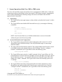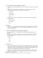
1
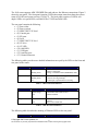
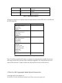
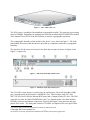
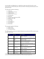
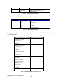
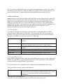
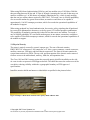
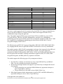
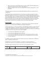
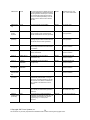
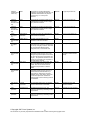
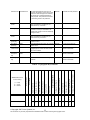
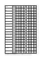
Cisco 1841 Integrated Services Routers
with
AIM-VPN/BPII-Plus
and
Cisco 2801 Integrated Services Routers
with
AIM-VPN/EPII-Plus
FIPS 140-2 Non Proprietary Security Policy
Level 2 Validation
Version 1.6
September 8, 2008
© Copyright 2007 Cisco Systems, Inc.
This document may be freely reproduced and distributed whole and intact including this Copyright Notice.
Table of Contents
1
INTRODUCTION.................................................................................................................. 3
1.1 PURPOSE ............................................................................................................................. 3
1.2 REFERENCES ....................................................................................................................... 3
1.3 TERMINOLOGY .................................................................................................................... 3
1.4 DOCUMENT ORGANIZATION ................................................................................................ 3
2 CISCO 1841 AND 2801 ROUTERS......................................................................................... 5
2.1 THE 1841 CRYPTOGRAPHIC MODULE PHYSICAL CHARACTERISTICS ...................................... 5
2.2 THE CISCO 2801 CRYPTOGRAPHIC MODULE PHYSICAL CHARACTERISTICS............................ 7
2.3 ROLES AND SERVICES ........................................................................................................... 11
2.3.1. User Services ................................................................................................ 11
2.3.2 Crypto Officer Services .................................................................................. 11
2.3.3 Unauthenticated Services............................................................................... 12
2.3.4 Strength of Authentication .............................................................................. 12
2.4 PHYSICAL SECURITY ............................................................................................................. 13
2.5 CRYPTOGRAPHIC KEY MANAGEMENT .................................................................................. 17
2.6 SELF-TESTS ....................................................................................................................... 25
2.6.1 Self-tests performed by the IOS image ....................................................... 25
2.6.2 Self-tests performed by Onboard FPGA...................................................... 25
2.6.3 Self-tests performed by AIM ........................................................................ 26
3
SECURE OPERATION OF THE CISCO 1841 OR 2801 ROUTER ............................. 27
3.1
3.2
3.3
3.4
3.5
3.6
INITIAL SETUP ................................................................................................................... 27
SYSTEM INITIALIZATION AND CONFIGURATION ................................................................. 27
IPSEC REQUIREMENTS AND CRYPTOGRAPHIC ALGORITHMS ............................................. 28
PROTOCOLS .......................................................................................................................... 28
SSLV3.1/TLS REQUIREMENTS AND CRYPTOGRAPHIC ALGORITHMS ................................ 28
REMOTE ACCESS ............................................................................................................... 28
© Copyright 2007 Cisco Systems, Inc.
2
This document may be freely reproduced and distributed whole and intact including this Copyright Notice.
1
Introduction
1.1 Purpose
This document is the non-proprietary Cryptographic Module Security Policy for the Cisco 1841
and 2801 Integrated Services Routers with AIM-VPN/BPII-Plus installed. This security policy
describes how the Cisco 1841 and 2801 Integrated Services Routers (Hardware Version: 1841 or
2801; Firmware Version: IOS 12.4 (15) T3) meet the security requirements of FIPS 140-2, and
how to operate the router in a secure FIPS 140-2 mode. This policy was prepared as part of the
Level 2 FIPS 140-2 validation of the Cisco 1841 or 2801 Integrated Services router.
FIPS 140-2 (Federal Information Processing Standards Publication 140-2 — Security
Requirements for Cryptographic Modules) details the U.S. Government requirements for
cryptographic modules. More information about the FIPS 140-2 standard and validation program
is available on the NIST website at http://csrc.nist.gov/groups/STM/index.html.
1.2 References
This document deals only with operations and capabilities of the 1841 and 2801 routers with
AIM modules in the technical terms of a FIPS 140-2 cryptographic module security policy.
More information is available on the routers from the following sources:
The Cisco Systems website contains information on the full line of Cisco Systems
routers. Please refer to the following website:
http://www.cisco.com/en/US/products/hw/routers/index.html
For answers to technical or sales related questions please refer to the contacts listed on
the Cisco Systems website at www.cisco.com.
The NIST Validated Modules website
(http://csrc.nist.gov/groups/STM/cmvp/validation.html) contains contact information
for answers to technical or sales-related questions for the module.
1.3 Terminology
In this document, the Cisco 1841 or 2801 routers are referred to as the router, the module, or the
system.
1.4 Document Organization
The Security Policy document is part of the complete FIPS 140-2 Submission Package. In
addition to this document, the Submission Package contains:
Vendor Evidence document
Finite State Machine
Other supporting documentation as additional references
This document provides an overview of the routers and explains their secure configuration and
operation. This introduction section is followed by Section 2, which details the general features
© Copyright 2007 Cisco Systems, Inc.
3
This document may be freely reproduced and distributed whole and intact including this Copyright Notice.
and functionality of the router. Section 3 specifically addresses the required configuration for
the FIPS-mode of operation.
With the exception of this Non-Proprietary Security Policy, the FIPS 140-2 Validation
Submission Documentation is Cisco-proprietary and is releasable only under appropriate nondisclosure agreements. For access to these documents, please contact Cisco Systems.
© Copyright 2007 Cisco Systems, Inc.
4
This document may be freely reproduced and distributed whole and intact including this Copyright Notice.
2 Cisco 1841 and 2801 Routers
Branch office networking requirements are dramatically evolving, driven by web and ecommerce applications to enhance productivity and merging the voice and data infrastructure to
reduce costs. The Cisco 1841 and 2801 routers provide a scalable, secure, manageable remote
access server that meets FIPS 140-2 Level 2 requirements. This section describes the general
features and functionality provided by the routers. The following subsections describe the
physical characteristics of the routers.
2.1 The 1841 Cryptographic Module Physical Characteristics
Figure 1 – The 1841 router case
The 1841 Router is a multiple-chip standalone cryptographic module. The router has a
processing speed of 240MHz. Depending on configuration, either the installed AIM-VPN/BPIIPlus module or the internal Giove FPGA or IOS software is used for cryptographic operations.
The cryptographic boundary of the module is the device’s case, shown in Figure 1. All of the
functionality discussed in this document is provided by components within this cryptographic
boundary.
The interface for the router is located on the rear panel as shown in Figure 2.
Figure 2 – Rear Panel Physical Interfaces
The Cisco 1841 router features a console port, an auxiliary port, Universal Serial Bus (USB)
port, two high-speed WAN interface card/WAN interface card/Voice interface card
(HWIC/WIC/VIC) slots, two 10/100 Fast Ethernet RJ45 ports, and a Compact Flash (CF) drive.
© Copyright 2007 Cisco Systems, Inc.
5
This document may be freely reproduced and distributed whole and intact including this Copyright Notice.
The 1841 router supports AIM-VPN/BPII-Plus card and two fast Ethernet connections. Figure 2
shows the rear panel. The front panel contains 2 LEDs that output status data about the system
status (SYS OK) and system activity (SYS ACT). The back panel consists of 8 LEDs: two
duplex LEDs, two speed LEDs, two link LEDs, CF LED and AIM LED.
The rear panel contains the following:
• (1) Power inlet
• (2) Power switch
• (3) HWIC/WIC/VIC slot 0
• (4) Console port
• (5) FE ports
• (6) Lock
• (7) HWIC/WIC/VIC slot 1
• (8) CF drive
• (9) CF LED
• (10) AIM LED
• (11) USB port
• (12) Auxiliary port
• (13) Ground connector
The following tables provide more detailed information conveyed by the LEDs on the front and
rear panel of the router:
Name
State
Description
System OK
Solid Green
Blinking Green
Router has successfully booted up and the
software is functional.
Booting or in ROM monitor (ROMMON) mode.
Solid Green
Blinking Green
Off
System is actively transferring packets.
System is servicing interrupts.
No interrupts or packet transfer occurring.
System Activity
Table 1 – 1841 Front Panel Indicators
Name
State
Description
AIM
Solid Green
Solid Orange
Off
AIM installed and initialized.
AIM installed and initialized error.
AIM not installed.
Compact Flash
Solid Green
Indicates that the flash is busy and should not be
removed.
OK to remove flash card.
Off
Table 2 – 1841 Rear Panel Indicators
The following table describes the meaning of Ethernet LEDs on the rear panel:
Name
State
© Copyright 2007 Cisco Systems, Inc.
Description
6
This document may be freely reproduced and distributed whole and intact including this Copyright Notice.
Duplex
Speed
Link
Solid Green
Off
Solid Green
Off
Solid Green
Off
Full-Duplex
Half-Duplex
100 Mbps
10 Mbps
Ethernet link is established
No link established
Table 3 – 1841 Ethernet Indicators
The physical interfaces are separated into the logical interfaces from FIPS 140-2 as described in
the following table:
Router Physical Interface
10/100 Ethernet LAN Ports
HWIC/WIC/VIC Ports
Console Port
Auxiliary Port
USB port
10/100 Ethernet LAN Ports
HWIC/WIC/VIC Ports
Console Port
Auxiliary Port
USB Port
10/100 Ethernet LAN Ports
HWIC/WIC/VIC Ports
Power Switch
Console Port
Auxiliary Port
10/100 Ethernet LAN Port LEDs
AIM LED
System OK LED
System Activity LED
Compact Flash LED
Console Port
Auxiliary Port
USB Port
Power Plug
FIPS 140-2 Logical Interface
Data Input Interface
Data Output Interface
Control Input Interface
Status Output Interface
Power Interface
Table 4 – 1841 FIPS 140-2 Logical Interfaces
The CF card that stored the IOS image is considered an internal memory module, because the
IOS image stored in the card may not be modified or upgraded. The card itself must never be
removed from the drive. Tamper evident seal will be placed over the card in the drive.
2.2 The Cisco 2801 Cryptographic Module Physical Characteristics
© Copyright 2007 Cisco Systems, Inc.
7
This document may be freely reproduced and distributed whole and intact including this Copyright Notice.
Figure 3 – Cisco 2801 router case
The 2801 router is a multiple-chip standalone cryptographic module. The router has a processing
speed of 240MHz. Depending on configuration, either the installed AIM-VPN/BPII-Plus module
or the internal Giove FPGA or the IOS software is used for cryptographic operations.
The cryptographic boundary of the module is the device’s case, shown in Figure 3. All of the
functionality discussed in this document is provided by components within this cryptographic
boundary.
The interfaces for the router are located on the front and rear panel as shown in Figure 4 and
Figure 5, respectively.
Figure 4 – 2801 Front Panel Physical Interfaces
Figure 5 – 2801 Rear Panel Physical Interfaces
The Cisco 2801 router features a console port, an auxiliary port, Universal Serial Bus (USB)
port, two high-speed WAN interface card (HWIC) slots, Voice interface card (VIC) slot,
WIC/VIC slot, two10/100 Fast Ethernet RJ45 ports, and a Compact Flash (CF) drive. The 2801
router has two slots for AIM-VPN/BPII-Plus cards1, two internal packet voice data modules
(PVDMs), and two fast Ethernet connections. Figure 4 and Figure 5 show the front and read
panels of the router. The front panel consists of 14 LEDs: two duplex LEDs, two speed LEDs,
1
The security policy covers the configuration in which one AIM card is used.
© Copyright 2007 Cisco Systems, Inc.
8
This document may be freely reproduced and distributed whole and intact including this Copyright Notice.
two link LEDs, two PVDM LEDs, two AIM LEDs, system status LED (SYS OK), system
activity (SYS ACT) LED, inline power LED, and CF LED. The back panel has the power inlet
and on/off switch.
The front panel contains the following:
• (1) VIC slot
• (2) HWIC/WIC/VIC slot 0
• (3) WIC/VIC slot
• (4) HWIC/WIC/VIC slot 1
• (5) Console port
• (6) FE ports
• (7) System status and activity LEDs
• (8) Inline power LED
• (9) USB port
• (10) FE LEDs
• (11) Auxiliary port
• (12) CF LED
• (13) CF drive
The rear panel contains the following:
• (1) Power inlet
• (2) Power switch
• (3) Ground connector
The following tables provide more detailed information conveyed by the LEDs on the front and
rear panel of the router:
Name
State
Description
System OK
Solid Green
Router has successfully booted up and the
software is functional.
Booting or in ROM monitor (ROMMON) mode.
Blinking Green
Inline Power
System Activity
Compact Flash
PVDM1
PVDM0
AIM1
Solid Green
Amber
Off
Solid Green
Blinking Green
Off
Solid Green
Off
Solid Green
Solid Orange
Off
Solid Green
Solid Orange
Off
Solid Green
Solid Orange
© Copyright 2007 Cisco Systems, Inc.
Inline power supply is working properly.
Inline power failure.
Inline power supply is not present.
System is actively transferring packets.
System is servicing interrupts.
No interrupts or packet transfer occurring.
Indicates that the flash is busy and should not be
removed.
OK to remove flash card.
PVDM1 installed and initialized.
PVDM1 installed and initialized error.
PVDM1 not installed.
PVDM0 installed and initialized.
PVDM0 installed and initialized error.
PVDM0 not installed.
AIM1 installed and initialized.
AIM1 installed and initialized error.
9
This document may be freely reproduced and distributed whole and intact including this Copyright Notice.
AIM0
Off
Solid Green
Solid Orange
Off
AIM1 not installed.
AIM0 installed and initialized.
AIM0 installed and initialized error.
AIM0 not installed.
Table 5 – 2801 Front Panel Indicators
The following table describes the meaning of Ethernet LEDs on the front panel:
Name
State
Duplex
Solid Green
Off
Solid Green
Off
Solid Green
Off
Speed
Link
Description
Full-Duplex
Half-Duplex
100 Mbps
10 Mbps
Ethernet link is established
No link established
Table 6 – 2801 Ethernet Indicators
The physical interfaces are separated into the logical interfaces from FIPS 140-2 as described in
the following table:
Router Physical Interface
10/100 Ethernet LAN Ports
HWIC/WIC/VIC Ports
Console Port
Auxiliary Port
USB Port
10/100 Ethernet LAN Ports
HWIC/WIC/VIC Ports
Console Port
Auxiliary Port
USB Port
10/100 Ethernet LAN Ports
HWIC/WIC/VIC Ports
Power Switch
Console Port
Auxiliary Port
10/100 Ethernet LAN Port LEDs
AIM LEDs
PVDM LEDs
Inline Power LED
System Activity LED
System OK LED
Compact Flash LED
Console Port
Auxiliary Port
USB Port
Power Plug
FIPS 140-2 Logical Interface
Data Input Interface
Data Output Interface
Control Input Interface
Status Output Interface
Power Interface
Table 7 – 2801 FIPS 140-2 Logical Interfaces
© Copyright 2007 Cisco Systems, Inc.
10
This document may be freely reproduced and distributed whole and intact including this Copyright Notice.
The CF card that stored the IOS image is considered an internal memory module. The reason is
the IOS image stored in the card cannot be modified or upgraded. The card itself must never be
removed from the drive. Tamper evident seal will be placed over the card in the drive.
2.3 Roles and Services
Authentication in Cisco 1841 and 2801 is role-based. There are two main roles in the router that
operators can assume: the Crypto Officer role and the User role. The administrator of the router
assumes the Crypto Officer role in order to configure and maintain the router using Crypto
Officer services, while the Users exercise only the basic User services. The module supports
RADIUS and TACACS+ for authentication. A complete description of all the management and
configuration capabilities of the router can be found in the Performing Basic System
Management manual and in the online help for the router.
2.3.1. User Services
Users enter the system by accessing the console port with a terminal program or via IPSec
protected telnet or SSH session to a LAN port. The IOS prompts the User for username and
password. If the password is correct, the User is allowed entry to the IOS executive program.
The services available to the User role consist of the following:
Status Functions
View state of interfaces and protocols, version of IOS currently
running.
Network Functions
Connect to other network devices through outgoing telnet, PPP, etc.
and initiate diagnostic network services (i.e., ping, mtrace).
Adjust the terminal session (e.g., lock the terminal, adjust flow
control).
Display directory of files kept in flash memory.
Negotiation and encrypted data transport via SSL/TLS.
Negotiation and encrypted data transport via EASY VPN.
Terminal Functions
Directory Services
SSL-TLS/VPN
EASY VPN
2.3.2 Crypto Officer Services
During initial configuration of the router, the Crypto Officer password (the “enable” password) is
defined. A Crypto Officer can assign permission to access the Crypto Officer role to additional
accounts, thereby creating additional Crypto Officers.
The Crypto Officer role is responsible for the configuration and maintenance of the router.
The Crypto Officer services consist of the following:
Configure the router
Define network interfaces and settings, create command aliases, set
the protocols the router will support, enable interfaces and network
services, set system date and time, and load authentication
information.
© Copyright 2007 Cisco Systems, Inc.
11
This document may be freely reproduced and distributed whole and intact including this Copyright Notice.
Define Rules and Filters Create packet Filters that are applied to User data streams on each
interface. Each Filter consists of a set of Rules, which define a set
of packets to permit or deny based on characteristics such as
protocol ID, addresses, ports, TCP connection establishment, or
packet direction.
View the router configuration, routing tables, active sessions, use
View Status Functions
gets to view SNMP MIB statistics, health, temperature, memory
status, voltage, packet statistics, review accounting logs, and view
physical interface status.
Log off users, shutdown or reload the router, erase the flash
Manage the router
memory, manually back up router configurations, view complete
configurations, manager user rights, and restore router
configurations.
Set up the configuration tables for IP tunneling. Set pre-shared keys
Set Encryption/Bypass
and algorithms to be used for each IP range or allow plaintext
packets to be set from specified IP address.
Bypass Mode
The routers implement an alternating bypass capability, in which some connections may be
cryptographically authenticated and encrypted while others may not. Two independent internal
actions are required in order to transition into each bypass state: First, the bypass state must be
configured by the Crypto Officer using “match address <ACL-name>" sub-command under
crypto map which defines what traffic is encrypted. Second, the module must receive a packet
that is destined for an IP that is not configured to receive encrypted data. The configuration table
uses an error detection code to detect integrity failures, and if an integrity error is detected, the
module will enter an error state in which no packets are routed. Therefore, a single error in the
configuration table cannot cause plaintext to be transmitted to an IP address for which it should
be encrypted.
2.3.3 Unauthenticated Services
The services available to unauthenticated users are:
• Viewing the status output from the module’s LEDs
• Powering the module on and off using the power switch
• Sending packets in bypass
2.3.4 Strength of Authentication
The security policy stipulates that all user passwords must be 8 alphanumeric characters, so the
password space is 2.8 trillion possible passwords. The possibility of randomly guessing a
password is thus far less than one in one million. To exceed a one in 100,000 probability of a
successful random password guess in one minute, an attacker would have to be capable of 28
million password attempts per minute, which far exceeds the operational capabilities of the
module to support.
© Copyright 2007 Cisco Systems, Inc.
12
This document may be freely reproduced and distributed whole and intact including this Copyright Notice.
When using RSA based authentication, RSA key pair has modulus size of 1024 bit to 2048 bit,
thus providing between 80 bits and 112 bits of strength. Assuming the low end of that range, an
attacker would have a 1 in 280 chance of randomly obtaining the key, which is much stronger
than the one in a million chance required by FIPS 140-2. To exceed a one in 100,000 probability
of a successful random key guess in one minute, an attacker would have to be capable of
approximately 1.8x10²¹ attempts per minute, which far exceeds the operational capabilities of
the modules to support.
When using preshared key based authentication, the security policy stipulates that all preshared
keys must be 8 alphanumeric characters, so the key space is 2.8 trillion possible combinations.
The possibility of randomly guessing this is thus far less than one in one million. To exceed a
one in 100,000 probability of a successful random guess in one minute, an attacker would have
to be capable of 28 million attempts per minute, which far exceeds the operational capabilities of
the module to support.
2.4 Physical Security
The router is entirely encased by a metal, opaque case. The rear of the unit contains
HWIC/WIC/VIC connectors, LAN connectors, a CF drive, power connector, console connector,
auxiliary connector, USB port, and fast Ethernet connectors. The front of the unit contains the
system status and activity LEDs. The top, side, and front portion of the chassis can be removed
to allow access to the motherboard, memory, AIM slot, and expansion slots.
The Cisco 1841 and 2801 routers require that a special opacity shield be installed over the side
air vents in order to operate in FIPS-approved mode. The shield decreases the surface area of the
vent holes, reducing visibility within the cryptographic boundary to FIPS-approved
specifications.
Install the opacity shields and tamper evident labels as specified in the pictures below:
Figure 6 Tamper evident labels attached on the opacity shield of Router 1841
© Copyright 2007 Cisco Systems, Inc.
13
This document may be freely reproduced and distributed whole and intact including this Copyright Notice.
Figure 7 Tamper evident labels attached on the opacity shield of Router 1841
Figure 8 Opacity shield attached on the side panel of router 2801
Figure 9 Tamper evident label attached on the opacity shield of Router 2801
© Copyright 2007 Cisco Systems, Inc.
14
This document may be freely reproduced and distributed whole and intact including this Copyright Notice.
Figure 10 Tamper evident label attached on the opacity shield of Router 2801
Once the router has been configured in to meet FIPS 140-2 Level 2 requirements, the router
cannot be accessed without signs of tampering. To seal the system, apply serialized, tamperevidence labels as follows:
For Cisco 1841 router:
1. Clean the cover of any grease, dirt, or oil before applying the tamper evidence
labels. Alcohol-based cleaning pads are recommended for this purpose. The
temperature of the router should be above 10°C.
2. The tamper evidence label should be placed over the CF card in the slot so that
any attempt to remove the card will show sign of tampering.
3. The tamper evidence label should be placed so that the one half of the label
covers the enclosure and the other half covers the port adapter slot.
4. The tamper evidence label should be placed so that the one half of the label
covers the enclosure and the other half covers the rear panel.
5. Place tamper evident labels on the opacity shield as shown in Figures 6 and 7.
6. The labels completely cure within five minutes.
Figures 11 and 12 show the additional tamper evidence label placements for the Cisco
1841.
© Copyright 2007 Cisco Systems, Inc.
15
This document may be freely reproduced and distributed whole and intact including this Copyright Notice.
Figure 11 – Cisco 1841 Tamper Evident Label Placement (Back View)
Figure 12 – Cisco 1841 Tamper Evident Label Placement (Front View)
For Cisco 2801 router:
1. Clean the cover of any grease, dirt, or oil before applying the tamper evidence
labels. Alcohol-based cleaning pads are recommended for this purpose. The
temperature of the router should be above 10°C.
2. The tamper evidence label should be placed so that one half of the label covers
the front panel and the other half covers the enclosure.
3. The tamper evidence label should be placed over the CF card in the slot so that
any attempt to remove the card will show sign of tampering.
4. The tamper evidence label should be placed so that the one half of the label
covers the enclosure and the other half covers the port adapter slot.
5. Place tamper evident labels on the opacity shield as shown in Figures 9 and 10.
6. The labels completely cure within five minutes.
Figures 13 and 14 show the additional tamper evidence label placements for the 2801.
© Copyright 2007 Cisco Systems, Inc.
16
This document may be freely reproduced and distributed whole and intact including this Copyright Notice.
Figure 13 – Cisco 2801 Tamper Evident Label Placement (Back View)
Figure 14 – Cisco 2801 Tamper Evident Label Placement (Front View)
The tamper evidence seals are produced from a special thin gauge vinyl with self-adhesive
backing. Any attempt to open the router will damage the tamper evidence seals or the material of
the module cover. Since the tamper evidence seals have non-repeated serial numbers, they can be
inspected for damage and compared against the applied serial numbers to verify that the module
has not been tampered. Tamper evidence seals can also be inspected for signs of tampering,
which include the following: curled corners, bubbling, crinkling, rips, tears, and slices. The word
“OPEN” will appear if the label was peeled back.
2.5 Cryptographic Key Management
The router securely administers both cryptographic keys and other critical security parameters
such as passwords. The tamper evidence seals provide physical protection for all keys. All keys
are also protected by the password-protection on the Crypto Officer role login, and can be
zeroized by the Crypto Officer. All zeroization consists of overwriting the memory that stored
the key. Keys are exchanged and entered electronically or via Internet Key Exchange (IKE) or
SSL handshake protocols.
The routers support the following FIPS-2 approved algorithm implementations:
Algorithm
Algorithm Certificate Number
Software (IOS) Implementations
AES
795
Triple-DES
683
SHA-1, SHA-256, SHA-512
794
HMAC-SHA-1
436
© Copyright 2007 Cisco Systems, Inc.
17
This document may be freely reproduced and distributed whole and intact including this Copyright Notice.
X9.31 PRNG
RSA
456
379
Onboard FPGA Implementations
AES
Triple-DES
SHA-1
HMAC-SHA-1
181
283
267
27
AIM Module Implementations
AES
Triple-DES
SHA-1
HMAC-SHA-1
X9.31 PRNG
RSA
100
213
401
38
80
383
The router is in the approved mode of operation only when FIPS 140-2 approved algorithms are
used (except DH and RSA key transport which are allowed in the approved mode for key
establishment despite being non-approved).
Note: The module supports DH key sizes of 1024 and 1536 bits and RSA key sizes of 1024,
1536 and 2048 bits. Therefore, the Diffie Hellmann Key agreement, key establishment
methodology provides between 80-bits and 96-bits of encryption strength per NIST 800-57. RSA
Key wrapping, key establishment methodology provides between 80-bits and 112-bits of
encryption strength per NIST 800-57.
The following are not FIPS 140-2 approved Algorithms: DES, RC4, MD5, HMAC-MD5, RSA
key wrapping and DH; however again DH and RSA are allowed for use in key establishment.
The module contains a HiFn 7814-W cryptographic accelerator chip, integrated in the AIM card.
Unless the AIM card is disabled by the Crypto Officer with the “no crypto engine aim”
command, the HiFn 7814-W provides AES (128-bit, 192-bit, and 256-bit) and Triple-DES (168bit) encryption; MD5 and SHA-1 hashing; and hardware support for DH, X9.31 RNG, RSA
encryption/decryption, and RSA public key signature/verification.
The module supports the following types of key management schemes:
1. Pre-shared key exchange via electronic key entry. Triple-DES/AES key and HMACSHA-1 key are exchanged and entered electronically.
2. Internet Key Exchange method with support for pre-shared keys exchanged and entered
electronically.
• The pre-shared keys are used with Diffie-Hellman key agreement technique to
derive Triple-DES or AES keys.
• The pre-shared key is also used to derive HMAC-SHA-1 key.
3. RSA digital signatures based authentication is used for IKE, with Diffie-Hellman Key
agreement technique to derive AES or Triple-DES keys.
© Copyright 2007 Cisco Systems, Inc.
18
This document may be freely reproduced and distributed whole and intact including this Copyright Notice.
4. RSA encrypted nonces based authentication is used for IKE, with Diffie-Hellman Key
agreement technique to derive AES or Triple-DES keys.
5. RSA key transport is used to derive the Triple-DES or AES keys during SSLv3.1/TLS
handshake.
The module supports commercially available Diffie-Hellman and RSA key transport for key
establishment.
All pre-shared keys are associated with the CO role that created the keys, and the CO role is
protected by a password. Therefore, the CO password is associated with all the pre-shared keys.
The Crypto Officer needs to be authenticated to store keys. All Diffie-Hellman (DH) keys agreed
upon for individual tunnels are directly associated with that specific tunnel only via the IKE
protocol. RSA Public keys are entered into the modules using digital certificates which contain
relevant data such as the name of the public key's owner, which associates the key with the
correct entity. All other keys are associated with the user/role that entered them.
Key Zeroization:
Each key can be zeroized by sending the “no” command prior to the key function commands.
This will zeroize each key from the DRAM, the running configuration.
“Clear Crypto IPSec SA” will zeroize the IPSec Triple-DES/AES session key (which is derived
using the Diffie-Hellman key agreement technique) from the DRAM. This session key is only
available in the DRAM; therefore this command will completely zeroize this key. The following
command will zeroize the pre-shared keys from the DRAM:
•
•
•
•
•
no set session-key inbound ah spi hex-key-data
no set session-key outbound ah spi hex-key-data
no set session-key inbound esp spi cipher hex-key-data [authenticator hex-key-data]
no set session-key outbound esp spi cipher hex-key-data [authenticator hex-key-data]
no crypto isakmp key
The DRAM running configuration must be copied to the start-up configuration in NVRAM in
order to completely zeroize the keys.
The RSA keys are zeroized by issuing the CLI command “crypto key zeroize rsa".
All SSL/TLS session keys are zeroized automatically at the end of the SSL/TLS session.
The module supports the following keys and critical security parameters (CSPs).
Key/CSP
Name
Algorithm
© Copyright 2007 Cisco Systems, Inc.
Description
19
Storage
Location
Zeroization Method
This document may be freely reproduced and distributed whole and intact including this Copyright Notice.
PRNG Seed
X9.31
This is the seed for X9.31 PRNG. This CSP
is stored in DRAM and updated periodically
after the generation of 400 bytes – after this
it is reseeded with router-derived entropy;
hence, it is zeroized periodically. Also, the
operator can turn off the router to zeroize
this CSP.
DRAM
Automatically every 400
bytes, or turn off the router.
PRNG Seed
Key
X9.31
This is the seed key for the PRNG.
DRAM
Turn off the router
Diffie Hellman
private
exponent
DH
The private exponent used in Diffie-Hellman
(DH) exchange as part of IKE. Zeroized
after DH shared secret has been generated.
DRAM
Automatically after shared
secret generated.
Diffie Hellman
public key
DH
The public key used in Diffie-Hellman (DH)
exchange as part of IKE. Zeroized after the
DH shared secret has been generated.
DRAM
Automatically after shared
secret generated.
skeyid
Keyed SHA-1
Value derived from the shared secret within
IKE exchange. Zeroized when IKE session
is terminated.
DRAM
Automatically after IKE
session terminated.
skeyid_d
Keyed SHA-1
The IKE key derivation key for non ISAKMP
security associations.
DRAM
Automatically after IKE
session terminated.
skeyid_a
HMAC-SHA-1
The ISAKMP security association
authentication key.
DRAM
Automatically after IKE
session terminated.
skeyid_e
TRIPLEDES/AES
The ISAKMP security association
encryption key.
DRAM
Automatically after IKE
session terminated.
IKE session
encrypt key
TRIPLEDES/AES
The IKE session encrypt key.
DRAM
Automatically after IKE
session terminated.
IKE session
authentication
key
HMAC-SHA-1
The IKE session authentication key.
DRAM
Automatically after IKE
session terminated.
ISAKMP
preshared
Shared secret
The key used to generate IKE skeyid during
preshared-key authentication. “no crypto
isakmp key” command zeroizes it. This key
can have two forms based on whether the
key is related to the hostname or the IP
address.
NVRAM
“# no crypto isakmp key”
IKE hash key
HMAC-SHA-1
This key generates the IKE shared secret
keys. This key is zeroized after generating
those keys.
DRAM
Automatically after generating
IKE shared secret keys.
IKE RSA
Authentication
private Key
RSA
RSA private key for IKE authentication.
Generated or entered like any RSA key, set
as IKE RSA Authentication Key with the
“crypto keyring” or “ca trust-point”
command.
NVRAM
“# crypto key zeroize rsa"
© Copyright 2007 Cisco Systems, Inc.
20
This document may be freely reproduced and distributed whole and intact including this Copyright Notice.
IKE RSA
Authentication
Public Key
RSA
RSA public key for IKE authentication.
Generated or entered like any RSA key, set
as IKE RSA Authentication Key with the
“crypto keyring” or “ca trust-point”
command.
NVRAM
“# crypto key zeroize rsa"
IKE RSA
Encrypted
Nonce Private
Key
RSA
RSA private key for IKE encrypted nonces.
Generated like any RSA, with the “usagekeys” parameter included.
NVRAM
“# crypto key zeroize rsa"
IKE RSA
Encrypted
Nonce Public
Key
RSA
RSA public key for IKE encrypted nonces.
Generated like any RSA, with the “usagekeys” parameter included.
NVRAM
“# crypto key zeroize rsa"
IPSec
encryption
key
DES/TRIPLEDES/AES
The IPSec encryption key. Zeroized when
IPSec session is terminated.
DRAM
“# Clear Crypto IPSec SA”
IPSec
authentication
key
Configuration
encryption
key
HMAC-SHA-1
The IPSec authentication key. The
zeroization is the same as above.
DRAM
“# Clear Crypto IPSec SA”
AES
The key used to encrypt values of the
configuration file. This key is zeroized when
the “no key config-key” is issued. Note that
this command does not decrypt the
configuration file, so zeroize with care.
NVRAM
“# no key config-key”
Router
authentication
key 1
Shared secret
DRAM
Automatically upon
completion of authentication
attempt.
PPP
authentication
key
RFC 1334
DRAM
Turn off the router.
Router
authentication
key 2
Shared Secret
This key is used by the router to
authenticate itself to the peer. The router
itself gets the password (that is used as this
key) from the AAA server and sends it onto
the peer. The password retrieved from the
AAA server is zeroized upon completion of
the authentication attempt.
The authentication key used in PPP. This
key is in the DRAM and not zeroized at
runtime. One can turn off the router to
zeroize this key because it is stored in
DRAM.
This key is used by the router to
authenticate itself to the peer. The key is
identical to Router authentication key 1
except that it is retrieved from the local
database (on the router itself). Issuing the
“no username password” zeroizes the
password (that is used as this key) from the
local database.
NVRAM
“# no username password”
SSH session
key
Various
symmetric
This is the SSH session key. It is zeroized
when the SSH session is terminated.
DRAM
Automatically when SSH
session terminated
User
password
Shared Secret
The password of the User role. This
password is zeroized by overwriting it with a
new password.
NVRAM
Overwrite with new password
Enable
password
Shared Secret
The plaintext password of the CO role. This
password is zeroized by overwriting it with a
new password.
NVRAM
Overwrite with new password
© Copyright 2007 Cisco Systems, Inc.
21
This document may be freely reproduced and distributed whole and intact including this Copyright Notice.
Enable secret
Shared Secret
The ciphertext password of the CO role.
However, the algorithm used to encrypt this
password is not FIPS approved. Therefore,
this password is considered plaintext for
FIPS purposes. This password is zeroized
by overwriting it with a new password.
NVRAM
Overwrite with new password
RADIUS
secret
Shared Secret
The RADIUS shared secret. This shared
secret is zeroized by executing the “no
radius-server key” command.
NVRAM
“# no radius-server key”
The fixed key used in Cisco vendor ID
generation. This key is embedded in the
module binary image and can be deleted by
erasing the Flash.
NVRAM
Deleted by erasing the Flash.
secret_1_0_0
TACACS+
secret
Shared Secret
The TACACS+ shared secret. This shared
secret is zeroized by executing the “no
tacacs-server key” command.
NVRAM
“# no tacacs-server key”
TLS server
private key
RSA
1024/1536/2048 bit RSA private key used
for SSLV3.1/TLS.
NVRAM
“# crypto key zeroize rsa"
TLS server
public key
RSA
1024/1536/2048 bit RSA public key used for
SSLV3.1/TLS.
NVRAM
“# crypto key zeroize rsa"
TLS premaster secret
Shared Secret
Shared Secret created using asymmetric
cryptography from which new TLS session
keys can be created
DRAM
Automatically when TLS
session is terminated
TLS
Encryption
Key
AES/TRIPLEDES
Key used to encrypt TLS session data
DRAM
Automatically when TLS
session is terminated
TLS Integrity
Key
HMAC-SHA-1
HMAC-SHA-1 used for TLS data integrity
protection
DRAM
Automatically when TLS
session is terminated
Security Relevant Data Item
PRNG Seed
d
r
PRNG Seed Key
d
r
© Copyright 2007 Cisco Systems, Inc.
22
This document may be freely reproduced and distributed whole and intact including this Copyright Notice.
r
w
d
r
w
d
Change WAN Interface Cards
Set Encryption/Bypass
Manage the Router
Status Functions
Define Rules and Filters
Configure the Router
Crypto Officer Role
EASY VPN
SSL-TLS/VPN
Directory Services
Terminal Functions
Network Functions
Status Functions
(r = read,
w = write,
d = delete)
User Role
SRDI/Role/Service
Access Policy
Roles/Service
Table 8 - Cryptographic Keys and CSPs
Diffie Hellman private
exponent
r
Diffie Hellman public
key
r
skeyid
r
w
d
r
w
d
r
w
d
r
w
d
r
w
d
r
w
d
r
w
d
r
w
d
r
w
d
r
w
d
r
w
d
r
w
d
r
w
d
r
w
d
r
skeyid_d
r
skeyid_a
r
skeyid_e
r
IKE session encrypt
key
r
IKE session
authentication key
r
ISAKMP preshared
r
IKE hash key
r
IKE RSA
Authentication private
Key
IKE RSA
Authentication Public
Key
IKE RSA Encrypted
Nonce Private Key
IKE RSA Encrypted
Nonce Public Key
r
r
r
r
IPSec encryption key
r
IPSec authentication
key
r
Configuration
encryption key
Router authentication
key 1
© Copyright 2007 Cisco Systems, Inc.
r
w
d
r
w
d
r
w
d
r
w
d
r
w
d
r
w
d
r
w
d
r
w
d
r
w
d
r
w
d
r
w
d
r
w
d
r
w
d
r
w
d
r
w
d
r
w
d
r
w
r
w
r
w
r
w
r
w
d
r
w
d
r
w
d
r
23
This document may be freely reproduced and distributed whole and intact including this Copyright Notice.
PPP authentication key
r
Router authentication
key 2
d
r
w
r
w
d
r
SSH session key
r
w
d
r
User password
r
w
d
r
w
d
r
w
d
r
w
d
r
Enable password
Enable secret
RADIUS secret
secret_1_0_0
r
w
d
TACACS+ secret
TLS server private key
r
TLS server public key
r
TLS pre-master secret
r
TLS Encryption Key
r
TLS Integrity Key
r
r
w
d
r
w
d
r
w
d
r
w
d
r
w
d
r
w
r
w
Table 9 – Role and Service Access to CSP
© Copyright 2007 Cisco Systems, Inc.
24
This document may be freely reproduced and distributed whole and intact including this Copyright Notice.
r
w
d
r
w
d
r
w
d
r
w
d
r
w
d
r
w
d
2.6 Self-Tests
In order to prevent any secure data from being released, it is important to test the cryptographic
components of a security module to insure all components are functioning correctly. The router
includes an array of self-tests that are run during startup and periodically during operations. All
self-tests are implemented by the software. An example of self-tests run at power-up is a
cryptographic known answer test (KAT) on each of the FIPS-approved cryptographic algorithms
and on the Diffie-Hellman algorithm. Examples of tests performed at startup are a software
integrity test using an EDC. Examples of tests run periodically or conditionally include: a bypass
mode test performed conditionally prior to executing IPSec, and a continuous random number
generator test. If any of the self-tests fail, the router transitions into an error state. In the error
state, all secure data transmission is halted and the router outputs status information indicating
the failure.
Examples of the errors that cause the system to transition to an error state:
•
•
•
•
•
IOS image integrity checksum failed
Microprocessor overheats and burns out
Known answer test failed
NVRAM module malfunction.
Temperature high warning
2.6.1
•
Self-tests performed by the IOS image
IOS Self Tests
o POST tests
AES Known Answer Test
RSA Signature Known Answer Test (both signature/verification)
Software/firmware test
Power up bypass test
RNG Known Answer Test
Diffie Hellman test
HMAC-SHA-1 Known Answer Test
SHA-1/256/512 Known Answer Test
Triple-DES Known Answer Test
o Conditional tests
Pairwise consistency test for RSA signature keys
Conditional bypass test
Continuous random number generation test for approved and nonapproved RNGs.
2.6.2
Self-tests performed by Onboard FPGA
o POST tests
© Copyright 2007 Cisco Systems, Inc.
25
This document may be freely reproduced and distributed whole and intact including this Copyright Notice.
2.6.3
•
AES Known Answer Test
Triple-DES Known Answer Test
SHA-1 Known Answer Test
HMAC-SHA-1 Known Answer Test
Self-tests performed by AIM
AIM Self Tests
o POST tests
AES Known Answer Test
Triple-DES Known Answer Test
SHA-1 Known Answer Test
HMAC-SHA-1 Known Answer Test
RNG Known Answer Test
Firmware integrity test
Diffie Hellman Test
RSA signature gen/ver known answer test
o Conditional Tests
Pairwise consistency test for RSA signature keys
Continuous RNG test for the hardware RNG
© Copyright 2007 Cisco Systems, Inc.
26
This document may be freely reproduced and distributed whole and intact including this Copyright Notice.
3
Secure Operation of the Cisco 1841 or 2801 router
The Cisco 1841 and 2801 routers meet all the Level 2 requirements for FIPS 140-2. Follow the
setting instructions provided below to place the module in FIPS-approved mode. Operating this
router without maintaining the following settings will remove the module from the FIPS
approved mode of operation.
3.1
Initial Setup
1. The Crypto Officer must apply tamper evidence labels as described in Section 2.4 of this
document.
2. The Crypto Officer must disable IOS Password Recovery by executing the following
commands:
configure terminal
no service password-recovery
end
show version
NOTE: Once Password Recovery is disabled, administrative access to the module
without the password will not be possible.
3.2
System Initialization and Configuration
1. The Crypto Officer must perform the initial configuration. IOS version 12.3(11)T3a,
Advanced Security build (advsecurity) is the only allowable image; no other image
should be loaded.
2. The value of the boot field must be 0x0102. This setting disables break from the console
to the ROM monitor and automatically boots the IOS image. From the “configure
terminal” command line, the Crypto Officer enters the following syntax:
config-register 0x0102
3. The Crypto Officer must create the “enable” password for the Crypto Officer role. The
password must be at least 8 characters (all digits; all lower and upper case letters; and all
special characters except ‘?’ are accepted) and is entered when the Crypto Officer first
engages the “enable” command. The Crypto Officer enters the following syntax at the
“#” prompt:
enable secret [PASSWORD]
4. The Crypto Officer must always assign passwords (of at least 8 characters) to users.
Identification and authentication on the console port is required for Users. From the
“configure terminal” command line, the Crypto Officer enters the following syntax:
line con 0
password [PASSWORD]
login local
© Copyright 2007 Cisco Systems, Inc.
27
This document may be freely reproduced and distributed whole and intact including this Copyright Notice.
3.3
IPSec Requirements and Cryptographic Algorithms
1. The only type of key management that is allowed in FIPS mode is Internet Key Exchange
(IKE).
2. Although the IOS implementation of IKE allows a number of algorithms, only the
following algorithms are allowed in a FIPS 140-2 configuration:
ah-sha-hmac
esp-sha-hmac
esp-Triple-DES
esp-aes
3. The following algorithms are not FIPS approved and should not be used during FIPSapproved mode:
MD-5 for signing
MD-5 HMAC
DES
3.4 Protocols
1. SNMP v3 over a secure IPSec tunnel may be employed for authenticated, secure SNMP
gets and sets. Since SNMP v2C uses community strings for authentication, only gets are
allowed under SNMP v2C.
3.5
SSLv3.1/TLS Requirements and Cryptographic Algorithms
When negotiating SSLv3.1/TLS cipher suites, only FIPS approved algorithms must be
specified.
All other versions of SSL except version 3.1 must not be used in FIPS mode of operation
The following algorithms are not FIPS approved and should not be used in the FIPSapproved mode:
MD5
RC4
RC2
DES
3.6
Remote Access
1. Telnet access to the module is only allowed via a secure IPSec tunnel between the remote
system and the module. The Crypto officer must configure the module so that any remote
connections via telnet are secured through IPSec, using FIPS-approved algorithms. Note
that all users must still authenticate after remote access is granted.
2. SSH access to the module is only allowed if SSH is configured to use a FIPS-approved
algorithm. The Crypto officer must configure the module so that SSH uses only FIPS© Copyright 2007 Cisco Systems, Inc.
28
This document may be freely reproduced and distributed whole and intact including this Copyright Notice.
approved algorithms. Note that all users must still authenticate after remote access is
granted.
© Copyright 2007 Cisco Systems, Inc.
29
This document may be freely reproduced and distributed whole and intact including this Copyright Notice.
CISCO EDITOR’S NOTE: You may now include all standard Cisco information included
in all documentation produced by Cisco. Be sure that the following line is in the legal
statements at the end of the document:
By printing or making a copy of this document, the user agrees to use this information for
product evaluation purposes only. Sale of this information in whole or in part is not
authorized by Cisco Systems.
© Copyright 2007 Cisco Systems, Inc.
30
This document may be freely reproduced and distributed whole and intact including this Copyright Notice.