1
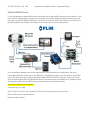
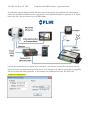
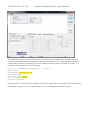
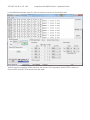
Integration with NMEA Devices Application Note MV-Series Thermal Cameras 432-0007-00-28-en-US v100 Integration with NMEA Devices – Application Note Contents Support.......................................................................................................................................................................................... 2 Overview ............................................................................................................................................................................................ 3 Scope ............................................................................................................................................................................................. 3 FLIR Certified Maritime Integrator (FCMI) Training......................................................................................................... 3 References .................................................................................................................................................................................... 4 NMEA 0183 Interface Standard ............................................................................................................................................. 4 System Connections ...................................................................................................................................................................... 5 Multiple Nexus Servers............................................................................................................................................................. 6 Radar Server Configuration .................................................................................................................................................... 6 Camera Configuration ...............................................................................................................................................................7 Radar Communications............................................................................................................................................................ 8 Moxa NPort Server .................................................................................................................................................................... 9 Radar Server Configuration Changes .................................................................................................................................14 Using NMEA Mode ...................................................................................................................................................................14 Multiple NMEA Devices ............................................................................................................................................................... 16 Troubleshooting ............................................................................................................................................................................ 20 Unable to see radar tracks in FSM....................................................................................................................................... 21 Camera does not follow radar tracks ................................................................................................................................. 21 Support If additional support is needed, please contact FLIR Technical Support either online or by telephone. All owners are encouraged to register their camera though the online support site. Online: http://support.flir.com/ Telephone: +1-888-747-3547 or +1-805-964-9797 432-0007-00-28-en-US v100 Integration with NMEA Devices – Application Note Overview This document describes how to integrate a FLIR MV-Series thermal camera with devices that use National Maritime Electronics Association (NMEA) communications. In particular, the camera can receive NMEA 0183 sentences from various types of devices, including: Radar GPS Gyrocompass In general, there are several ways to interconnect the camera and NMEA 0183 devices1. This document describes a few typical installations and provides information specific to the following third-party (nonFLIR) equipment: Moxa NPort Serial Ethernet Server Actisense NMEA Multiplexer ShipModul NMEA Multiplexer Antaira Power over Ethernet (PoE) switch Radar (generic NMEA 0183serial) A Windows PC (with a web browser and optionally running FLIR Sensors Manager software) Of course it is possible to use a wide variety of other brands of third-party devices, and the devices listed above are used as an example. The configurations provided in this document have been tested by FLIR with the MV-Series cameras. Scope This document provides a brief guide to connecting and configuring the necessary components for using NMEA 0183 devices with the FLIR camera. The user should have a basic understanding of the installation of these devices and the cables and interconnections between them. Complete details about the NMEA communications, configuration of cameras, IP networks and so on are generally beyond the scope of this document. FLIR Certified Maritime Integrator (FCMI) Training This configuration guide provides a brief description of the setup of these devices. For installers and integrators that are interested in a more advanced level of configuration, the FLIR Certified Maritime Integrator (FCMI) certification program offers hands-on training with a variety of FLIR cameras, and focuses on integration design and installation with other third-party devices and equipment. For more information, contact your local FLIR representative or visit one of the following web sites: http://www.flir.com/training 1 At this time, other maritime communication protocols such as NMEA 0183-HS and NMEA 2000 are not supported. 432-0007-00-28-en-US v100 Integration with NMEA Devices – Application Note References FLIR MV/MU-Series Installation Guide (Document # 432-0007-00-12) FLIR MV/MU-Series Operators Manual (Document # 432-0007-00-10) FLIR Sensors Manager (FSM) User Manual 2 http://ns.flir.com/downloads (manual also available from FSM Help menu once the software is installed) National Maritime Electronics Association http://www.nmea.org/ Antaira PoE Switch – LNP-0500-24-T http://www.antaira.com/products/power-over-ethernet/poe-switches/lnp-0500-24-t?pid=4899 Moxa Serial to Ethernet server – Nport P5150A Series Port http://www.moxa.com/product/NPort_P5150A.htm Actisense NMEA Multiplexer – NDC-4 NMEA Multiplexer http://www.actisense.com/products/nmea-0183/ndc4.html ShipModul MiniPlex-2E NMEA Multiplexer http://www.shipmodul.com/en/index.html NMEA 0183 Interface Standard The NMEA 0183 Standard, a communication standard defined by the NMEA organization (www.nmea.org), defines a communication protocol that enables navigation instruments and devices to exchange data with each other. The NMEA 0183 Interface Standard defines electrical signal requirements, data transmission protocol and time, and specific sentence formats for a 4800-baud serial data bus. With NMEA 0183, devices are characterized as either a talker (something that transmits NMEA data) or a listener (something that receives MMEA data). Each communication channel may have only one talker but many listeners. This standard is intended to support one-way serial data transmission from a single talker to one or more listeners. This data is in printable ASCII form and may include information such as position, speed, depth, frequency allocation, etc. It is common to integrate a FLIR camera with other devices that use NMEA 0183 communications. The camera, as a listener device, can receive position data from a GPS and compass that allows it to calculate its position relative to other objects such as radar tracks. It can also listen to a radar and respond to the radar track information by pointing toward (and following) a moving radar track. 2 Optional, if FSM is used 432-0007-00-28-en-US v100 Integration with NMEA Devices – Application Note System Connections It is assumed the camera is installed and operational, and can be controlled via the FLIR Joystick Control Unit (JCU). Warning: Do not connect a Power over Ethernet (PoE) Power Source Equipment (PSE) device (such as a PoE switch or injector) directly into the Ethernet port of the MV-Series camera. Damage to the camera could result and will void the manufacturer’s warranty. The Ethernet interface on the camera is a PSE device. In a simple installation, the FLIR JCU is connected directly to the camera Ethernet and draws its power from the camera. In this example, a PoE switch is used instead to power the JCU and interconnect it with the camera. In addition, a Serial to Ethernet Server is also connected to the PoE switch, and this allows the radar communications to be sent to the camera. Important: Per the warning above, the Ethernet connection from the camera is connected to the unpowered (non-PoE) port of the PoE switch. The switch shown has one unpowered port and 4 powered ports. Alternatively, it would be possible to use a non-PoE Ethernet switch, and use PoE Injectors to power the JCU and the Serial to Ethernet Server. The NMEA 0183 standard uses a simple ASCII serial communications protocol that defines how data are transmitted in a "sentence" from one "talker" (such as the radar) to one or more "listeners" (such as a camera) at a time. It is possible for a talker to have a unidirectional conversation with a listener, as the first example here will show. In subsequent examples, sentences from multiple sensors (Radar, GPS, etc.) will be combined using an NMEA multiplexer to talk to a single listener. 432-0007-00-28-en-US v100 Integration with NMEA Devices – Application Note Multiple Nexus Servers By default, the MV cameras have a configuration that includes two Nexus Servers: one for the camera and one for a radar. The Camera Server controls and monitors the various devices in the camera, such as the pan/tilt platform, the IR thermal cameras, the DLTV and LLTV visible cameras and other devices. The Radar Server controls and monitors a radar device (and optionally other NMEA devices) that are external to the cammera and allows the radar track information (or other NMEA information) to be sent to the camera. The Camera Server is configured with a Radar Interface module that allows it to listen to the Radar Server. Both the Camera Server and the Radar Server use the same IP address, but they each have a unique TCP port number3 for communications. In this way, the two servers appear on the network as separate virtual servers. If a PC is connected to the same network as the camera, JCU and other devices, the FSM sofware can be used as a convenient tool for making configuration changes, for monitoring the servers and devices and for troubleshooting communications issues. In FSM, each server will appear as a separate server, as shown to the right. Radar Server Configuration In general, it is possible to modify the Camera Server configuration by using a web browser to connect to the camera and make changes through the web interface. In order to modify the Radar Server configuration, it is necessary to download the configuration file from the camera, edit the file with a text editor (such as WordPad) and then upload it to the camera again. To download the configuration file, log in with a web browser as admin, then select Maintenance > Files > Configuration. Scroll down the page and locate the “Download” link and save the config file (server.ini) to a folder on the PC. Warning: When editing the server.ini conguration file, be very careful not to make any changes other than the changes described in this document. Prior to making any changes, make a backup copy of the server.ini file so that it can be restored if unexpected behavior results from unintended changes. 3 By default, the Camera Server uses port 1001 and the Radar Server uses port 1002. 432-0007-00-28-en-US v100 Integration with NMEA Devices – Application Note Geo-Referencing of the Sensors The Camera Server and the Radar Server can each have a georeference location. When the camera is installed on a vessel, the location information can come from a GPS and gyrocompass and the information is available as NMEA data directly from those devices or through the radar device. For port/harbor applications where the location of the camera is fixed, the location and heading information can be statically entered into the camera configuration. The Camera Server can have a different georeference location and heading than the Radar Server, but typically they are associated with each other, with an offset if they are in different locations on a larger ship. It is recommended that the Radar Server is configured to receive the live location information, and the Camera Server georeference can be associated with the Radar Server georeference. Camera Configuration The factory configuration already contains most of the configuration settings that are necessary for integration with a radar. If the factory default IP address is used (192.168.250.116) for the camera, it is not necessary to make any changes to the Camera Server configuration. In this example, the camera IP address is changed from the factory default to 192.168.250.98, and therefore it is necessary to make some additonal configuration changes. In particular, the camera has a Radar Interface Module that is configured with the IP address and port number of the Radar Server. In this example the Radar Interface IP address is changed to match the Camera Server IP address (the Port number 1002 is unchanged). To view or modify the settings, log in with a web browser and select Maintenance > Modules > Radar Interface. 432-0007-00-28-en-US v100 Integration with NMEA Devices – Application Note Radar Communications The radar device communicates NMEA 0183 sentences over a serial connection. For the first example, a Moxa Nport 5150 server serial port is connected to the serial interface of the radar, and allows the NMEA data to then be sent via the Ethernet over the network to the camera. The NPort connects to the network through the same PoE switch as the JCU. Refer to the manufacturer’s documentation for configuration and wiring information about the serial ports on the NPort server and on the radar. Specifically, ensure that both sides use the same signalling standard (RS422 or RS232), baud rate, and so on. Ensure the transmitted signals from the radar go to the receive side on the NPort. Since the radar does not connect directly to the camera, the camera must be able to pull in the radar data from the network. The Radar Server makes use of a UDP Terminal to make a connection with the NPort serial server. The Radar Server will listen for UDP communication packets (called datagrams) that are sent to a particular port number; in this case, port number 10001 will be used. The Moxa NPort server will also be configured to send datagrams to that same port number. 432-0007-00-28-en-US v100 Integration with NMEA Devices – Application Note Moxa NPort Server In order to use the NPort server on the network, it will need to have an IP address that is compatible with the IP address of the camera, so it is likely it will need to be changed. In this example the NPort is assigned IP address 192.168.250.97. Refer to the NPort user manual for information about using the NPort Administrator software to change the IP address and other configuration parameters. Use the Configuration option to set the Serial parameters to match the radar. For example, NMEA 1083 specification uses a baud rate of 4800. 432-0007-00-28-en-US v100 Integration with NMEA Devices – Application Note Select the Operating Mode tab to set up the UDP Terminal. Select the Modify checkbox and then the Settings button to change the UDP Mode settings. 432-0007-00-28-en-US v100 Integration with NMEA Devices – Application Note Set the UDP Mode Settings Destination Begin and End IP addresses to the IP address of the camera, and set the port number to 10001. These correspond to the UDP Terminal that is configured in the Radar Server. 432-0007-00-28-en-US v100 Integration with NMEA Devices – Application Note Once the UDP Mode is set up, it is possible to use the Port Monitor feature to confirm if the radar data is received by the NPort server. Select the Port Monitor Option, then select “Add” at the top. Once the NPort device is displayed, select the checkbox next to it and click OK. 432-0007-00-28-en-US v100 Integration with NMEA Devices – Application Note Use the Port Monitor settings (right click on one of the column headings) to add a column that displays the number of transmitted and received packets – for example, “Tx/Rx after Mon”. Select the “Go” button and then confirm the number of received packets (Rx) is non-zero. 432-0007-00-28-en-US v100 Integration with NMEA Devices – Application Note Radar Server Configuration Changes Warning: do not make any changes to the configuration file other than the changes listed here in this document. Open the server.ini configuration file with a text editor. Some parts of the file contain parameters that relate to Sensor 0 (the Camera Server) and some contain parameters that relate to Sensor 1 (the Radar Server). Perform a search of the file for “Sensor 1” to locate the first line related to the Radar Server. Locate the section related to the UDP Terminal: [Sensor 1: TERMINAL Configuration - Device 0] Enabled=yes IP Address=192.168.250.97 UDP Port=10001 UDP Local Port=10001 Local IP Address=eth0 Type=UDP Terminal Confirm the IP Address and UDP Port correspond to the address and port of the NPort Serial server. [Sensor 1: RADAR Configuration - Device 0] Enabled=yes Terminal Type=7 Associated TERMINAL UDP Id=0 Associated GEO Id=0 Track Refreshment Timeout=10 Minimum Speed Filter=0 NMEA Timeout=150 Ignore Checksum=1 GPS Override=0 Compass Azimuth Override=0 NMEA Sentence Version=1 Raise alarm for hidden tracks=0 Raise alarm for friend tracks=0 Type=Radar NMEA Serial The Radar Configuration section above shows the radar server will use the UDP Terminal with ID=0. Using NMEA Mode To allow the camera to respond to radar track information, it is necessary to enable the NMEA Mode through the on-screen menu. On the JCU, press the Menu button to bring up the on-screen menu. 432-0007-00-28-en-US v100 Integration with NMEA Devices – Application Note Use the joystick to move down to “Special Modes”, and select that option. In the Special Modes Menu, select “NMEA Modes”. In the NMEA Modes Menu, select the “Track NMEA Mode: Disabled” line to enable tracking. Confirm the camera responds to radar tracks. 432-0007-00-28-en-US v100 Integration with NMEA Devices – Application Note Multiple NMEA Devices In the next example, multiple NMEA talker devices are able to send NMEA sentences to the camera. In this case, the GPS, gyrocompass, and radar are connected to an NMEA multiplexer (also known as mux), and the output port of the NMEA multiplexer is connected to serial port of the Moxa NPort server used in the previous example. No changes are required on the camera or the camera configuration. As in the previous example, refer to the manufacturer’s documentation for configuration and wiring information about the serial ports on the NMEA mux, Serial Ethenet server and other devices. Specifically, ensure that both sides use the same signalling standard (RS422 or RS232), baud rate, and so on. Ensure the transmitted signals from the NMEA devices go to the receive side on the NMEA mux. Similarly, ensure the transmit signals from the NMEA mux go to the receive side of the NPort server. Add info here about how to operate… Track scan via jcu or FSM Set PT device to use “exit and comeback” so that it will continue scanning if jcu moved Need to filter certain nmea sentences? Need to include certain “ “ 432-0007-00-28-en-US v100 Integration with NMEA Devices – Application Note An alternative solution allows provides the same type of connectivity and combines the Serial Ethernet server and the NMEA Multiplexer into a single device. The ShipModul MiniPlex-2E operates on 12-24VDC rather than PoE, and can connect up to 4 NMEA talkers. Connect the ShipModul mux to power and to the switch. Use the MPX-Config tool that comes with the device to search the network and locate the device. Then change the IP address to one that is compatible with the camera and other equipment. In this example, the ShipModul mux uses 192.168.250.94. ShipModul configuration? 432-0007-00-28-en-US v100 Integration with NMEA Devices – Application Note The ShipModul uses port number 10110, which is a registered port for NMEA data. Therefore the UDP Terminal of the Radar Server configuration is also set up to use port 10110. Open the camera server.ini configuration file with a text editor, as in the first example. Perform a search of the file for “Sensor 1” to locate the section related to the UDP Terminal: [Sensor 1: TERMINAL Configuration - Device 0] Enabled=yes IP Address=192.168.250.94 UDP Port=10001 UDP Local Port=10110 Local IP Address=eth0 Type=UDP Terminal Modify the file to use the correct IP address and UDP port, save the file, and upload it to the camera with a web browser. Stop and start the Camera Server so the new configuration settings are used. 432-0007-00-28-en-US v100 Integration with NMEA Devices – Application Note In the ShipModul software, select the Connect button to connect to the MiniPlex mux. Verify if the mux is receiving NMEA data from the devices. The image above shows $GPGLL sentences from the GPS and $RATTM sentences from the radar. 432-0007-00-28-en-US v100 Integration with NMEA Devices – Application Note Troubleshooting The FLIR Sensors Manager software is a convenient tool for monitoring and troubleshooting the camera and the Radar Server. If it has not already been done, install and run FSM, and use Setup > Discovery to add the Camera and Radar Servers to the list of Active Sensors. In FSM, select View > Tracks Panel, confirm the radar tracks are displayed. If FSM Pro is used, it is possible to display sensors and radar tracks on the Map. Right click on the map and select “Find in Map…” and select either the camera or radar. 432-0007-00-28-en-US v100 Integration with NMEA Devices – Application Note Unable to see radar tracks in FSM Check the connections to the camera, and make sure it is receiving power. If possible, confirm there is a video signal by temporarily plugging the video cable into another video monitor. If the M-Series camera is in Standby mode, no video will be displayed. Generally the camera will be in the Park position if it is in Standby mode. Confirm the camera goes through the initial pan/tilt initialization when the power is turned on. Be sure to allow time for the camera and the display to fully boot up and for the MFD to “discover” the camera. When the camera is first powered on, it will temporarily display the FLIR splash screen on the video for a few seconds, and then the video will stop again until the JCU or MFD connects to the camera and brings it out of Standby mode. Camera does not follow radar tracks By default, the Track NMEA Mode becomes disabled when the camera is moved manual with the joystick. If necessary, follow the steps described above to use the on-screen menu to enable Track NMEA Mode. . FLIR Commercial Systems, Inc. 70 Castilian Drive Goleta, CA 93117 Phone: 888.747.FLIR (888.747.3547) International: +1.805.964.9797 www.flir.com Document Number: 432-0007-00-28-en-US Version: 100 Issue Date: October 2014