1
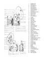
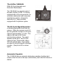
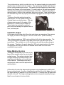
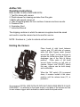
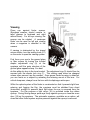
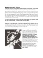
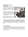
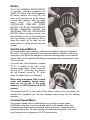
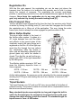
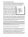
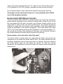
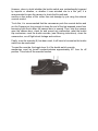
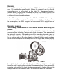
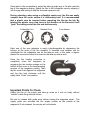
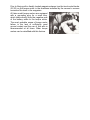
Arriflex 16S
Operating
Instructions
1
2
3
4
5
6
7
8
9
10
11
12
13
14
15
16
17
18
19
20
21
22
23
24
25
26
27
28
29
30
31
32
33
34
35
36
37
38
39
40
41
42
43
44
45
46
47
48
Film Magazine (200 ft.)
Magazine Cover Lock
Latch for Magazine Lock
Camera Cover Lock
Diopter Adjustment Ring
Eyepiece Retaining Ring
Lock for Diopter Adjustment
Power Cable Lock
Override Button for Buckle Switch
Camera “ON” Switch
Camera ”OFF” Switch
Cover Lock Spring
Magazine Opening Cover
Tachometer
Footage Counter
Frame Counter
Power Connector
Viewfinder Cover Door
Accessory Shoe
Focusing Lever
Contour Hand Grip
Re-Set for Footage Counter
Re-Set for Frame Counter
Motor Lock Lever
Variable Speed Motor
Rheostat To Control Camera Speed
Inching Knob
Eyelet for Carrying Strap
Knurled Dis, Camera Take-Up
Locking Levers for Torque Motor
Torque Motor
Knurled Disc, Magazine Take-Up
Film Supply Counter
Forward/Reverse Switch for Torque Motor
Knurled Disc, Magazine Supply
Knurled Disc, Camera Supply
Lens Turret
Lens Retaining Lever
Filter Stage, Rotating
Filter Stage, Stationary
Matte Slot
Matte Box
Matte Box Beam
Lock Screw for Matte Box
Lock Screw for Matte Box Stages
Diaphragm Ring
Turret-Rotating Grips
Eyelet for Carrying Strap
The Arriflex 16S/B-GS
[With 60-Cycle Generator and
Automatic Startmarker]
The 16S /B-GS is a special model of
the basic Arrilflex 16 S/B. It is factory
equipped with a 60-cycle generator, an
automatic startmarker and a manually
operated cue marker, designed to
work with all ¼” tape recorders
equipped with the pilotone system.
The 60-Cycle Signal Generator
A miniature generator is built into the
camera. When the camera runs at 24
fps, the generator ooutput is a 60-cycle
signal of approximately 1.2 volts. This
signal is the heart of all Piloton
synchronizing systems. The output
appears across pins 1 and 2 of the
camera’s 5-pin Tuchel outlet, after a
300 milli-second delay. Sync cables
are used to carry this signal to the tape
recorder. (See price list for various
types).
Automatic Clapstick
The 16 S/B-GS has an automatic startmarker capable of putting startmarks on the film and on the tape, automatically, each time the camera is
started.
The miniature lamp, which is visible just over the camera hand grip is paired with
another lamp, located inside the camera. The inside lamp flashes whole frames
of film, during camera run-up time. The result is that the beginning of each take,
three or four frames of film are flashed. The start mark on the tape corresponds
with the point just past the last flashed frame on the film. Light from the interior
marking lamp in visible in the viewfinder, during run-up time. Note that the lamps
are activated only when a properly wired cable is plugged into the 5-pin Tuchel
outlet.
To remove the start marking lamps for
replacement, turn the plastic housing on
its metal base counterclockwise. The pair
of lamps are secured to the ends of the
black rod (P1) which may be lifted out.
These lamps are resistance matched
pairs, and must always be replaced with a
new, matched pair.
8 Volt DC Output
At the same time, during which the start mark lamps are energized, the camera
will supply 8 volts DC through pin 3 on the Tuchel outlet. (See schematic).
This voltage energizes a 1000 cycle oscillator built into the tape recorder. The
1000 cycle signal is recorded on the tape and serves as a start-mark in the
sound track. The oscillator is cut off simultaneously with the marking lamps in
the camera. Therefore, the point where the 100 cycle signal ends on the tape,
corresponds with the point where the flashed frames end on the film and
constitute the sync point.
Edge Marking System
The edge-marking lamp is mounted in the
base of the camera under the coin slotted
contact screw. The mating indicator lamp
for edge marking is located on top of the
small generator casting on the right side
of the camera. These lamps are also a
matched pair and should be replaced with
matched pairs.
At the start of a take, the edge-marking lamps work simultaneously with the full
frame marking lamps. However, these lamps mark the film at the edge only, and
the edge marking is displace on the film by about 3 ½ frames from the aperture in
direction of travel. The edge-marking lamp can be energized manually during a
take for event marks of various kinds.
Arriflex 16S
Operating Instructions
Each Arriflex 16 S/B is SUPPLIED WITH:
1 Test film taken with camera
2 Plastic skewer for cleaning emulsion from film gate.
3 Bottle with special camera oil
4 Tube of special grease for lens cavities of camera and lens mounts.
5 Pressure Oiler
6 Guarantee Card
7 Instruction Manual
The shipping container in which the camera is supplies should be saved
and used in case the camera has to be sent for service.
NOTE: Numbers in ( ) refer to callouts on front overleaf.
Holding the Camera
Place thumb of right hand between
contour grip (21) and side of camera,
while the other fingers reach forward
around the “bulge” so they are free to
actuate the follow-focus grips (38) and
diaphragm ring of the lens in taking
position.
Place palm of left hand
around finder housing on left side of
camera, fingers over ON-OFF switch
this way, camera can be held steady
and comfortably.
When the “ON” switch (10) is pressed
down, it remains locked in the downposition until the release lever (11) is
pushed in.
An accessory PISTOL GRIP WITH OR WITHOUT SHOULDER BRACE IS ALSO
AVAILABLE. It is attached to the tripod socket in the base of the camea and has
its own release trigger which activates a switch inside the tripod socket.
Viewing
Place eye against finder eyecup.
(Eyeglass wearers should remove or
raise glasses to forehead and sight
without them). For left eye viewing, the
eyecup can be rotated. A periscope
finder can be used for left eye viewing
when a magazine is attached to the
camera.
If viewing is obstructed by the closed
mirroe shutter, turn the inching knob (27)
on the motor to open the viewing system.
First focus your eye to the ground glass
or fiber screen by turning the knurled
diopter adjustment ring (5) at the
eyepiece until the grain structure of the
ground glass appears sharp. You best
do this without a lens in the turret socket. The adjustment ring (5) should then be
secured with the diopter lock ring (7). This setting need never be changed
unless other persons use the camera. Once proper finder focusing is obtained,
you can focus on a subject by actuating the focusing mount of the lens. For
critical sharpness, always focus the lens with its diaphragm wide open.
While the optical system of the finder is constructed so that it prevents light from
entering and fogging the film, the eyepiece must be shielded from direct
(horizontal) sunlight or powerful back light when the eye is removed from the
eyepiece. For this purpose a light cover (18) is provided inside the rubber
eyecup. During filming always press eye firmly against eyecup or close the cover
door (18) on the eyepiece. The automatic eyepiece, available as an option, will
close the reflex finder system anytime pressure against the eyecup is removed.
Detachable Eyepiece
The detachable eyepiece, the same on
all Arriflex cameras, permits the use of a
variety of finder accessories like the
PERISOPIC ACCESSORY FINDER,
WHICH FACILITATES VIEWING FROM
THE SIDE OR THE TOP (for instance if
camera is on a microscope or copy
stand), or viewing with the left eye when
a 400 ft. MAGAZINE is attached to the
camera. A finder extender can also be
mounted when working in unusual
situation.
To remove the eyepiece, turn the knurled chrome-plated collar (6) clockwise. To
re-mount it, first engage the keyed flange properly then turn the collar (6)
counterclockwise. Exercise care not to cross thread the collar and make sure the
eyepiece is flush against the finder flange.
The rubber eyecup swivels freely in its ball-stop bearing and can be pulled off for
cleaning. The installation of a prescription corrective lens – of 15.5mm diameter
– is possible in a specially provided recess in the eyecup assembly.
Ground Glasses/Fiber Screens
The standard ground glass, supplied with the camera, is marked to show: center
cross, TV safe action and camera aperture. It can be interchanged for a special
ground glass with center cross and projector aperture only, or for a clear glass
with reference reticle for cinemicroscopy. (See price list for details.) Such
installations must be done only by skilled, Arriflex trained technicians and require
special tools.
All 16 S cameras equipped with APEC have the new fiber screen in place of a
ground glass. The fiber screen has distinctly greater brilliance, which is
especially noticeable in low light conditions or at small lens apertures. Fiber
screens are available for later installation in any Arriflex 16S above serial number
8981.
On Arriflex 16S cameras with Serial Number 6101 to 8980,
exchangeability of the ground glass to fiber screen is possible by using a finder
modernization kit (see price list for details).
The Three Lens Divergent Turret
The Arriflex 16 features a heavy-duty three-lens turret (37). The lenses are
mounted in a divergent manner of 21o to prevent optical and mechanical
interference between wide-angle and telephoto lenses.
A turret lock prevents the turret from being turned unintentionally. To lock the
turret, be sure the taking lens is precisely located by the turret detent
mechanism, then turn the lock lever clockwise as far as it will go. (See
illustration 6). To open the turret lock, turn th elever counterclockwise. Three
turret grips (47) make it easy to rotate the selected lens into taking position.
Always turn the turret by means of the grips, never by the lenses.
The back of each turret grip (47) is coded with either one, two or three dots.
These dots can be seen from the rear, while filming and can therefore be used to
indicate if the wide angle, normal or telephoto lens is in taking position.
Standard Lens Mounts
Two of the three lens cavities are for
standard Arriflex lens mounts. These
are ideal for fixed focal length lenses or
average size. To seat lenses in standard
Arri mounts: Press the pair of lens
locking levers (38) together, align the
keyway in the lens mount with the key in
the socket and carefully place the lens in
the socket. When the lents is seated,
release the lock levers, and check that
the lens is locked safely in place.
Always keep lens mount and lens socket
lubricated with a trace of the instrument
grease supplied with your camera.
To remove standard Arri mounted lenses: Press the lens locking levers (38)
together, then lift the lens straight out. Always keep empty lens cavities covered
with cavity caps.
Bayonet Lock Lens Mounts
One of the three lens sockets is for lenses in Bayonet Lock Mounts. This stronger
mount, is primarily intended for zoom lenses or other larger, heavier lenses.
To seat Bayonet Lock Lenses: Note the locking lugs at the rear of the lens mount
-position the lens so the lens data engravings are on the top, and the lugs are in
line with the keyways in the socket. (See illustration). Insert the lens as far as it
will go and then twist the entire lens clockwise by 15°. You will hear and feel the
mount latch into place. The lens locking levers (38) operate automatically in this
case and need not be depressed.
To remove Bayonet Lock Lenses: Press the Locking Levers (38) together, rotate
the lens counterclockwise. Then lift the lens out of the cavity.
Always try to hold the lens on a fixed part of the barrel. Don't rotate the lens for
mounting purposes by the focusing or iris rings. The Bayonet Lock mount
provides seating and lens alignment of superior precision and durability. Use
zoom lenses always in Arri Bayonet Lock Lens Mounts.
Lenses for Arriflex are made by the
world's leading optical manufacturers
and represent the ultimate in optical
and mechanical quality. Lenses
available for the Arriflex 16 range in
focal length from 5.7mm on up.
Standard lenses are equipped with
follow-focus grips (20) and most have
diaphragm click-stops. Use only
lenses in genuine Arriflex lens mounts
to insure trouble-free operation and
optimum image quality. For extremely
long or heavy lenses, lens support
systems of various types are
available, the most practical of which
is the standard ARRIFLEX bridge
plate system.
Standard Matte Box and
Filter Holder
To attach the matte box to the camera,
slide the end of the boom into the special
shoe (19) on the front of the camera
housing. Lock it into position by turning
the knurled (44) knob at the front of the
boom.
The rear stage of the matte box is
adjustable to accommodate lenses of
various lengths. The front is adjustable
for optimum protection from side light
and to prevent vignetting irrespective of
lens focal length.
SPECIAL EFFECT MATTES such as
key holes, binoculars, etc. can be
inserted into a slot in the front frame.
Two filter stages accept rectangular 60x75mm and 60x100mm GLASS FILTERS,
or ARRI FILTER HOLDERS with frame for 2" square gelatine or glass filters. One
of the stages can be rotated for use with GRADUATED OR POLARIZING
FILTERS. (For filter listing see separate filter price list). The rear opening of the
matte box is threaded to accept a screw-in adapter ring for Series 8 mounted
filters.
Universal Matte Box
The Universal Matte Box, especially designed for Zoom lenses also
accommodates many standard and telephoto fixed focal length lenses. Features
include adjustable front and rear standards, two filter stages, one of which may
be rotated for polarizing filters. 3"x3", 75mmx100mm graduated filters, and 4"x4"
filters can be used.
Motors
The 8 Volt VARIABLE SPEED MOTOR
is generally standard equipment for
16S/B. All motors are interchangeable.
By simply opening lock lever (24), the
motor may be pulled out of the camera
housing and replaced with any other
motor
such
as
-GOVERNOR
CONTROLLED CONSTANT SPEED
MOTOR, 110V 60 HZ SYNCHRONOUS
MOTOR, ANIMATION MOTOR and
UNIVERSAL CRYSTAL CONTROLLED
MOTOR. When mounting a motor, care
must be taken to line up the locating pin
with the keyway in the camera and to
insert the motor, all the way into the
motor cavity to insure proper electrical
contact.
Variable Speed Motors
By turning ribbed motor housing, a rheostat is actuated to regulate the speed of
the motor. The figures around the motor shell are arbitrary, however, after some
experience, they permit the operator to reset the camera quickly for any desired
speed. (With, a full charged 8 Volt battery the rheostat will be set between 3 and
4 to give 24 fps.
A knurled disc (see Illustration) marked
"R"-"F" is located at the back of the
variable speed motor. When turned all
the way to "F" (click stop), the camera
will run Forward; turned to "R" (clickstop), the camera will run in Reverse.
When using a magazine, both, camera
motor and magazine torque motor,
must be set to run in the same
direction, i.e. BOTH forward or BOTH
reverse!
The inching knob (27) in the center of the motor is used to turn the shutter and
actuate the registration pin and film transport claw during the film loading
operation.
Constant Speed Motor
The constant speed motor is used when only one single camera speed
(24/25Fps) is required. In size and shape similar to the variable motor, the
constant speed motor uses a centrifugal switch (governor) to keep the motor
speed accurate within 1% under varying load and power conditions. The motor
runs forward only and requires an 8V DC power source.
Power Sources/Batteries
Power requirements for Arriflex 16 with variable speed or constant speed motor
and with 400 ft. magazine are:
8 Volts DC (under load); 3.6 Amperes running; starting surge up to 6 Amperes
depending on ambient temperature and condition of equipment.
For the crystal controlled motor, 12VDC is required. Be sure the magazine torque
motor is a 12V version when using the crystal motor with 400 ft. magazine. (See
special instructions.)
Arriflex-made batteries are available in a wide variety of sizes, power output and
connections. You may use any suitable power supply which is capable of
delivering the required voltage and amperes. Generally, batteries with less than
1.8 Ampere/hours at rated voltage are not practical.
In an emergency, the Arriflex 16S may be operated from a 6 Volt auto battery.
Maximum camera speed will be approximately 24 FPS with the variable speed
motor. A 12 Volt auto battery may generate excessive torque unless the battery
is tapped for 8 Volts. MAKE CERTAIN PROPER POLARITY IS MAINTAINED.
To use any Arriflex DC motor on 110 Volt AC current, a power supply with
transformer and rectifier is necessary. (See 16S price list).
Camera Tachometer & Film Counter
The Arriflex 16S/B is equipped with a tachometer (14), which registers filming
speeds from 5 to 50 frames per second.
It registers forward speeds only. The camera should never be run above the
maximum speed indicated by the tachometer.
Below the tachometer are the film footage counter (15) and frame counter (16).
Both can be zeroed easily by their respective setting discs (22/23).
Film Gate
The Arriflex film gate is extra long (3 inches) and has a full-length rear pressure
pad with a side pressure rail. Cross stages around the picture frame both on the
front and back plates prevent "film breathing". Made of stainless steel, tapped to
high precision and wear chrome-plated, the Arriflex film gate is probably one of
the most trouble-free yet highest quality film gates of any camera. It is important
to clean the gate regularly of film emulsion and film base deposits.
Never use any metal tools on the gate surfaces! Use only the plastic
skewer supplied with the camera and a clean untreated optical cloth.
Registration Pin
With the film gate opened, the registration pin can be seen just above the
transport claw. Its function is to locate the film precisely and to hold it in place
during the moment of exposure. The registration pin ensures rock-steady
pictures, a repetitively precise film line, and increased tolerance against film pitch
changes. Never force the registration pin in any way while cleaning the
gate, only activate it by turning the motor inching knob [27].
Film Transport Claw
The film transport claw engages the film from the front, the emulsion side. Watch
its action by turning the inching knob (27) and note that it engages the film while
the registration pin is lifting out of the perforation. This way, during the entire
frame cycle, there is always one claw engaged for positive control of film.
Mirror Reflex Shutter
The mirror reflex shutter is the heart of
the Arriflex reflex system. It rotates at a
45° angle between lens and film plane
and reflects to the ground glass of the
viewfinder exactly the same image as is
registered on the film. All of the light rays
reach the film through the lens without
any interference while the shutter is
open, and are alternately reflected to the
ground glass only while the shutter is
closed. Thus the film, as well as the eye,
always gets 100% of the light transmitted
by the taking lens.
The effective shutter opening is 180° and
gives the following exposure times at
various speeds:
8 FPS – 1/16 sec.
24 FPS – 1/48 sec.
12 FPS – 1/24 sec.
32 FPS – 1/64 sec.
16 FPS – 1/32 sec.
48 FPS – 1/96 sec.
As this table indicates, the exposure can be calculated for the camera speed by
doubling the FPS figure and reading the result as a fraction of a second (180°
shutter only).
Tripod Sockets
Two tripod threads, one 1/4" and one 3/8" size, are provided in the bottom of
camera housing. This socket is made of tool steel and is a replaceable insert in
the aluminum camera housing.
Many standard tripod screws might be too long and trigger the built-in
switch for the pistol grip. An excessively long tripod screw could even
damage the switch housing inside the camera. The standard length for
tripod screw is 7mm = 0.280 inches.
Camera Loading & Threading
Turn cover lock (14) from “C” to “O” and lift cover. Lay cover down and be sure
switch is in OFF position otherwise switch activating pin could get bent. Place
100 ft. film spool on upper spindle. Pull off about 2 feet of film. Both spindles
have an automatic lock to hold film spool in place in any camera position. To take
film spool out, push button in center of spindle and tilt camera sideways.
Open film gate by pressing latching knob
inwards and swing the pressure pad
assembly open on its hinges. Before
threading film, open pressure roller assembly
A by pressing button B. Thread film around
sprocket drum C. Swing off pressure roller 01, if necessary. Then arrest film by swinging
back pressure roller D-1. Lead film to gate E
by forming an upper loop according to
marking in the camera body above the film
gate. Register pin F must be in disengaged
(up) position. If it is not, turn motor inching
knob (27) until pin is lifted over the film guide.
Place film into gate in such a way that a perforation hole engages the protruding
film transport claw. Hold film down with two fingers, one at either end of the gate
and turn inching knob (27) until the registration pin engages film and holds it in
place. Be sure film lays flush down against the aperture plate, then close gate.
Thread film around sprocket drum G, forming a lower loop according to the
marking in the camera body below the gate, and close pressure roller D2, At this
point the roller assembly A should be securely closed.
The sprockets are designed to accept either single or double perforated
film. It is important to set film properly by moving it back and forth with two
fingers over each sprocket until you can feel that the sprocket teeth have
engaged the perforations. Push the leading end of the film into the take-up slot
of an empty 100 ft. daylight spool and secure it by a few turns. Place the spool on
the take-up spindle and be sure it "'snaps" into place securely.
The knurled spindle discs (28,36) outside of the camera serve to take up film
slack by turning them in direction of the engraved arrows.
When the film is running, these discs turn and indicate whether film goes forward
or backward. When film has run off, the supply spindle stops turning thus
indicating the end of the film in the event the buckle switch is not functioning.
Prior to switching camera "ON" or closing the cover, move a few inches of
film through gate by manually turning inching knob [27] clockwise.
With camera connected to power, push down internal switch (K) and watch about
2 feet of film roll through the camera. (Note: A "100 ft. roll" of film on a daylight
loading spool actually measures 106 feet to permit enough leader and trailer.)
Then close camera and turn lock (4) to "C", Again, be sure that the door switch
(10) is released, in the "OFF" position, otherwise the cover cannot be closed.
Run off approximately 5 feet of light-struck leader before beginning filming.
Set footage counter and frame counter to –0– by rotating the discs (22/23)
next to the plexiglass windows.
Buckle Switch With Manual Override
The buckle switch (film end switch H) works properly only if the lower film loop is
formed exactly according to the marking in camera body. When the end of the
film has passed the film gate, the lower loop shortens, thereby pulling up the
switch roller H, which in turn cuts off the camera motor. The camera can only be
switched on again after the pressure roller assembly A has been opened and
closed as described in the previous paragraph. The buckle switch also stays
"OFF" in the event that the pressure roller assembly A is not closed properly, i.e.,
the camera will not start. Any shortening of the lower loop during the running of
the camera actuates the buckle switch to prevent film jamming.
Never actuate or force the switch roller H by hand!
The buckle switch override button (9) underneath the finder tube permits the
cameraman to circumvent the buckle switch circuit. On certain adverse and rare
occasions, particularly due to heavy-duty shock or vibration, the micro switch of
the buckle switch might trip and switch the camera off. With the override
mechanism the cameraman can quickly restart the camera without opening the
camera cover.
However, when in doubt whether the buckle switch was unintentionally triggered
by impacts or vibration, or whether it was actuated due to a film jam, it is
recommended to open the camera, to check the film path and
sacrifice a few inches of film rather than risk damage by just using the external
override control.
To do this, it is recommended that the cameraman push the override button and
run the Camera just long enough to keep the end of the last exposed scene from
becoming light struck when the camera door is opened. Then, stop the camera,
open the camera door, check for and correct any malfunction, reset the buckle
trip mechanism, reset the buckle override, (see following instructions), close the
camera door, run-off light struck footage and continue.
Finally, once the override (9) has been used, it will have to be reset so the buckle
switch can be reactivated.
To reset the override, the toggle lever U of the buckle switch override
mechanism must be turned counterclockwise approximately 45° from its off
position. This shuts off the override function.
Magazine
The top of the camera housing accepts the 400 ft. film magazine. A light-tight
cover (13) protects the magazine slot. Before the magazine can be attached,
remove the cover by pulling firmly on this latch (12). The camera housing is
internally wired to supply power to the take-up motor. The contact is visible once
the cover is pulled off. This power contact is silver-plated and must be kept clean
at all times to insure lowest resistance.
Arriflex 16S magazines are designed for 400 ft. and 200 ft. 16mm single or
double perforated film on plastic core (darkroom loads) B-wound. By removing
the core adapters, the 400 ft. magazine will also accept 200 ft. daylight loads on
spools.
Magazine Loading
The following procedure must be done in total darkness when using core
load film.
To open magazine cover, depress the safety latch (leaf spring) and turn lock (2)
counterclockwise to its stop. Swing supply guide arm up until it is arrested near
top casting of magazine. With leading end of film unwinding clockwise, place roll
on left spindle by pushing plastic film core onto core adapter. Do not "dish" the
film by pushing down on the outer diameter of the roll! Unlatch supply guide arm
and be sure the flanges of the roller slip over the film edges and guide it properly.
Now slip the leading end of the film through the left hand slot between the light
trap rollers until it exists on the outside of the magazine throat. Then reverse this
procedure and push the film back into the compartment by feeding it through the
take-up slot which is on the other side of the throat from where the film exited.
Once back in the compartment, arrest the take-up guide arm in it's latch near the
top of the magazine casting. Attach the film to the collapsible core by slipping it
into the gap and locking it with the chromed expansion clip.
During unloading, when using a collapsible center core, the film can easily
unspool from the center unless it is deliberately held. It is recommended
that a plastic core be inserted before repacking the film for the lab. By
twisting the plastic core a few turns in the direction of the film wind it will
"grab" the trailing end of the film and hold securely.
Collapsible Core
Standard Core
Core Adapter
Each one of the core adapters is easily interchangeable by depressing the
buttons at the ends of the film spindles. A standard core adapter can be
substituted for the collapsible one on the take-up side. In this case, a regular
plastic film core would have to be used on the take-up side as well.
Once the film loading procedure is
completed, close the magazine by
engaging the two location prongs on the
bottom of the cover in the corresponding
grooves of the magazine casting. Then
lay the cover flush against the magazine
and turn the lock clockwise until the
safety latch "clicks" into position.
Important Points To Check
Attach the film on the supply and take-up cores so it will run freely without
"wobble" inside the guide arm rollers.
Be sure to release both guide arms before closing the magazine cover. The
supply guide arm activates the film supply counter on the outside of the
magazine! If not released, the counter will not indicate.
Wind sufficient film onto the take-up core to be certain It won't slip, that it
will wind even and in line with the guide roller. Always be sure to remove
the core adapter from the exposed roll before repacking film for the lab.
Many adapters have been lost this way. Practice the Ioading with outdated
film, in the light, a few times and these procedures will quickly become
routine.
The Arriflex 16S has the sprocket drive in the camera compartment. To load the
camera with a pre-Ioaded magazine, proceed as follows:
Pull enough film out of the throat of the magazine so you can guide it through the
magazine opening on the camera casting. Then engage the dovetail wedge on
the rear of the magazine in the corresponding
wedge on the camera, lift the magazine lock
(3) which contracts the locking wedges and
lower the front wedge into the camera
casting. With the magazine loosely seated in
the camera casting, pull the latch (3) of the
magazine lock down and the resulting
expansion of the wedges will secure the
magazine to the camera. To prevent an
accidental releasing of the lock, always hook
the safety catch into the lock latch.
With the magazine safely mounted on the camera, proceed with the film loading
in the same manner as described previously for 100 ft. camera loads.
Torque Motor
The magazine take-up motor, torque motor, attaches to the body of the magazine
by means of two lock levers (30) and becomes an integral part of it.
To attach the torque motor to the magazine,
both levers (30) are turned upward, the
motor is pressed against the corresponding
area of the magazine and then both levers
(30) are turned in direction of the arrows
until they are reasonably tight.
In the center of the torque motor casting is
the lever (34) which controls the
forward/reverse running of the magazine. It
is important that the setting of this lever
corresponds with the directional setting of
the camera drive motor.
Prior to filming with a freshly loaded magazine always turn the two knurled knobs
(32,35) on the torque motor in the directions indicated by the arrows to remove
excessive film slack in the magazine.
All later model torque motors are equipped
with a grounding plug for a small wire,
which leads directly from the negative pole
of the battery cable to the torque motor.
The most probable cause of torque motor
failure is the lack of sufficiently good
ground contact and the use of this wire is
recommended at all times. Older torque
motors can be retrofitted with this feature.
Servicing and Maintenance
The Arriflex 16S is built with utmost precision and is famous for its
ruggedness. It will give absolute satisfaction if treated as any precision
instrument should be treated, and if serviced at regular intervals, consistent
with the amount of use, and the following recommendations.
The most important rule is:
KEEP THE CAMERA SPOTLESSLY CLEAN – INSIDE AND OUT!
Particular attention must be given to the film gate. It is precision-lapped and
chrome-plated to minimize film emulsion to settle. However, some emulsion
deposit is inevitable and will vary with the type of film used, the relative
humidity and other factors.
The film gate should be checked and cleaned every 400 ft. roll and it
should be carefully inspected and thoroughly cleaned at the end of each
day's filming. Remove emulsion deposit with the plastic skewer supplied
with the camera (NEVER METAL). If emulsion is hardened on film gate,
remove it with a Q-tip dipped in acetone or alcohol. Be careful not to get
any solvent on any optical surface. Acetone will also dissolve paint. After
cleaning, polish gently with chamois or other soft, clean optical cloth.
From time to time, the lens mounts and the three lens sockets in the turret
should be cleaned to remove dirt and dust. After such cleaning, re-lubricate
lightly with the special grease supplied with the camera.
The standard lubricants used with the Arriflex are suitable for use in
temperatures down to -20°C, provided the camera is in good working
condition, and the lubricants in the camera mechanism itself are clean and
uncontaminated by dirt.
On special request and for extra charge, Arriflex cameras can be winterized
at our Service Department to function at still lower temperatures. For
details, consult section on "low temperature operation."
Lubrication
Your camera has been properly lubricated at the factory and is ready for
operation. Do not oil before using unless camera had been stored and
not been used for more than 12 months.
After each run of 30,000- 50,000 feet of film through the camera, camera
should be lightly oiled at two oil valves marked with arrows (one near the
film gate, and one near the supply spindle). Only use the ball and pressure
oiler supplied with your camera and the special oil contained therein. Do
not overoil -too much oiling is as bad as too little!
By observing the following "DON'Ts” you will protect the continued safe and
reliable operation of your Arriflex:
DON'T run camera without film at high speeds.
DON'T attempt to disassemble any part of the camera. This should be
done by factory-trained personnel only.
DON'T touch mirror shutter with fingers. Clean it only with soft camel hair
brush. In any case, a spot on the mirror does not affect the picture.
DON'T exchange covers of different camera (serial numbers are engraved
on each coyer and camera).
DON'T use old or shrunk film; the registration pin's stroke is adjusted to the
perforation pitch of fresh film (0.2994) according to ASA specifications.
DON'T allow cameras to be serviced by unqualified service shops. Arriflex
cameras require special knowledge and experience.
DON'T neglect to have your camera serviced after approximately every
200,000 ft., or every two years, whichever comes first. Service should be
more frequent under adverse conditions.
Our Service Department welcomes your inquiries and is anxious to help
you with any problem or unforeseen requirements you might have.