1
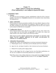
PNlib - An Advanced Petri Net Library for Hybrid Process Modeling Sabrina Proß Bernhard Bachmann University of Applied Sciences, Department of Engineering and Mathematics Am Stadtholz 24, 33609 Bielefeld [email protected] [email protected] Abstract A new Petri net library, called PNlib, is presented to enable graphical hierarchical modeling, hybrid simu lation, and animation of processes in life sciences, technical applications, among others. In order to model these most different processes, a new power and universally usable mathematical modeling ful concept – xHPN (extended Hybrid Petri Net) – has been established. This formalism is used as specification for the PNlib (Petri Net library) realized by the object-oriented modeling language Modelica. The application of the new environment is demonstrated by three selected examples. The first example demonstrates the representation of functional principles by a model of a Senseo coffee machine and the second one is a model of a printing production process. The third example presents the applicability of modeling business processes. All models are provided as application cases in the library. Keywords: Petri nets; hybrid modeling; xHPN; process modeling 1 qualitative modeling approach as well as the quantitative one. Furthermore, the processes can be modeled discretely as well as continuously, refer to [2]. In addition, discrete and continuous processes can also be combined within a Petri net model to socalled hybrid Petri nets first introduced by David and Alla [3]. The Petri net formalism with all its extensions is so powerful that nearly all other formalisms are included. Hence, only one formalism is needed regardless of the approach (qualitative vs. quantitative, discrete vs. continuous vs. hybrid, deterministic vs. stochastic) which is appropriate for the respective system. The Petri net formalism is easy to understand for researchers from different disciplines. It is an ideal way for intuitive representing and communicating data and new knowledge of mechanisms and processes. Furthermore, Petri nets allow hierarchical structuring of models and, therefore, offer the possibility of different detailed views for every observer of the model. Introduction The Petri net formalism was first introduced by Carl Adam Petri in 1962 for modeling and visualization of concurrency, parallelism, synchronization, resource sharing, and non-determinism [1]. A Petri net is a graph with two different kinds of nodes, called transitions and places; thereby, places and transitions are connected by arcs. Every place in a Petri net can contain a non-negative integer number of tokens. These tokens initiate transitions to fire according to specific conditions. These firings lead to changes of the tokens in the places. In the recent years, Petri nets with their various extensions are becoming increasingly popular. They have been proven to be a universal graphical modeling concept for representing different systems in nearly all degrees of abstraction. They support the DOI 10.3384/ecp1207647 Figure 1: Relationships between the different formalisms There are already three Petri net libraries available on the Modelica homepage (www.modelica.org). The first was developed by Mosterman et al. and enables the modeling of a restricted class of discrete Proceedings of the 9th International Modelica Conference September 3-5, 2012, Munich, Germany 47 PNlib - An Advanced Petri Net Library for Hybrid Process Modeling Petri nets, called normal Petri nets [4]. The places of normal Petri nets can only contain zero or one token. Additionally, all arcs have the weight one and external signals initiate the firing of transitions. If a conflict occurs between two or more transitions, the transition with the highest priority fires. Hence, only deterministic behavior is represented by this kind of Petri net. The second Petri net library is an extension of the previous one and was developed by Fabricius [5]. The places are able to contain a non-negative integer number of tokens and can be provided with nonnegative integer minimum and maximum capacities. Furthermore, the transitions are timed with fixed or stochastic delays. The third library, called StateGraph, is based on Grafcharts which combines the function chart formalism of Grafcet with the hierarchical states of Statecharts [6]. The StateGraph library is part of the Modelica standard library and was developed by Otter et al. [7]. The relationships between the mentioned concepts are displayed in Figure 1. To enable modeling of different systems with Petri nets in Modelica, the existing libraries have to be extended by the following aspects: Transfer of the discrete Petri net concept to a continuous one, Support of edges with (functional) weightings, Support of test-, inhibitor, and read arcs, Support of (different) conflict resolutions (random decisions), Combination of discrete and continuous Petri net elements to hybrid Petri nets. 2 Extended Hybrid Petri Nets The extended Hybrid Petri Net (xHPN) formalism comprises three different processes, called transitions: discrete, stochastic, and continuous transition, two different states, called places: discrete and continuous places, and four different arcs: normal, inhibitor, test, and read arcs. The icons of the formalism are shown in Figure 2. Discrete places contain a non-negative integer quantity, called tokens or marks, while continuous places contain a non-negative real quantity. These marks initiate transitions to fire according to specific conditions and the firings lead to changes of the marks in the connected places. Discrete transitions are provided with delays and firing conditions and fire first when the associated delay is passed and the conditions are fulfilled. The- 48 se fixed delays can be replaced by exponentially distributed random variables, then, the corresponding transition is called stochastic transition. Thereby, the characteristic parameter λ of the exponential distribution can depend functionally on the markings of several places and is recalculated at each point in time when the respective transition becomes active or when one or more markings of involved places change. Based on the characteristic parameter, the next putative firing time of the transition can be evaluated and it fires when this point in time is reached. xHPN: Extended Hybrid Petri Nets Places Transitions (time-)discrete state (integer quantity) (time-)discrete process (event) stochastic process (random event) continuous state (real quantity) Arcs „normal“ arc continuous process (flow) inhibitor arc test arc read arc Figure 2: Icons of the xHPN formalism Both - discrete and stochastic transitions - fire by removing the arc weight from all input places and adding the arc weight to all output places. On the contrary, the firing of continuous transitions takes place as a continuous flow determined by the firing speed which can depend functionally on markings and/or time. Places and transitions are connected by normal arcs which are weighted by non-negative integers and real numbers, respectively. But also functions can be written at the arcs depending on the current markings of the places and/or time. Places can also be connected to transitions by test, inhibitor, and read arcs. Then their markings do not change during the firing process. In the case of test and inhibitor arcs, the markings are only read to influence the time of firing while read arcs only indicate the usage of the marking in the transition, e.g. for firing conditions or speed functions. If a place is connected to a transition by a test arc, the marking of the place must be greater than the arc weight to enable firing. If a place is connected to a transition by an inhibitor arc, the marking of the place must be less than the arc weight to enable firing. In both cases the markings of the places are not changed by firing. The conversion of a discrete to a continuous marking is realized by connecting a discrete transition to a continuous place and the conversion from a continuous to a discrete marking is realized by con- Proceedings of the 9th International Modelica Conference September 3-5, 2012, Munich Germany DOI 10.3384/ecp1207647 Session 1A: Hybrid Modeling necting a continuous place to a discrete transition. However, the conversion process is always performed by discrete transitions, discrete places can only influence the time when continuous transitions fire but their marking cannot be changed during the continuous firing process. Figure 3 shows examples of these two basic principles: T1 can only fire when P1 has more than zero marks and P3 has at least one mark (influence), T2 can only fire when P4 has at least one mark and P6 has at least 5.4 marks (influence), T3 fires by removing one mark from P7 and adding 1.8 marks to P8 (conversion), T4 fires by removing 0.8 marks from P9 and adding one mark to P10 (conversion). P1 8.6 1 T1 P2 1.8 1 P4 1 T2 1 P3 This can be either done by providing the transitions with priorities or probabilities. In the first case, a deterministic process decides which place enables which transition and in the second case the enabling is performed at random; thereby transitions assigned with a high probability are chosen preferentially. 1 T1 P1 0 v1=3 1 1.8 P7 P8 0.0 P9 3.4 0.8 T4 P2 0 1 T2 T3 1 Figure 4: Example of a type-1-conflict; P1 has not enough tokens to fire T1 and T2 simultaneously. v1=3 1 T2 2 1 P6 8.9 P3 P7 P2 P1 P1 0 1 5.4 5.4 1 P5 1 T1 1 T1 1 3 1 v2=10.5 1 T5 v5=3 1 T2 P2 0 3 1 v2=7.5 T3 v5=3 P10 2 P8 T5 1 P3 0 2 3 T6 T3 v6=2 v3=6 1 P3 0 3 T6 3.6 v3=11.7 3.2 2.4 Marks v6=2 2 2.8 T4 2.0 1 P4 0 2 T4 1 P4 0 1.6 v4=1 1.2 v4=1 0.8 0.4 0.0 0.0 0.5 1.0 1.5 Time 2.0 2.5 3.0 Figure 3: Basic concepts of hybrid Petri nets and marking evolution of places and achieved by firing with a delay of 1 of the bottom left Petri net. It is important to mention that a discrete transition fires always in a discrete manner by removing and adding marks after a delay is passed regardless of whether a discrete or a continuous place is connected to it. However, a continuous transition fires always by a continuous flow so that a discrete place can only be connected to continuous transition if it is input as well as output of the transition with arcs of same weight. In this way continuous transitions can only be influenced by discrete places but discrete markings cannot be changed by continuous firing. Several conflicts can occur when the places have to enable their connected active transitions. Possibly, a discrete place or a continuous place connected to discrete transitions has not enough marks to enable all discrete output transitions simultaneously or cannot receive marks from all active input transitions due to the maximum capacity. Then a conflict arises that has to be resolved (type-1-conflict, see Figure 4). DOI 10.3384/ecp1207647 Figure 5: Example of a type-2-conflict; the input speed of P2 and P3 is not sufficient to fire T5 and T6 with the determined speed. Another conflict can occur between a continuous place and two or more continuous transitions when the input speed is not sufficient to fire all output transitions with the respective speed or when the output speed is not sufficient to fire all input transitions with the respective speed (type-2-conflict, see Figure 5). This conflict is solved by sharing the speeds proportional to the assigned maximum speeds (cf. [8]). P1 8.6 1 T1 P2 1.8 1 1 1 P3 T3 1 T2 1 v3=1 d2=2 Figure 6: Example of a type-3-conflict; at time 0, T1 becomes active and fires continuously. At time 2, the delay of T2 is passed and it becomes firable. At this point in time, P3 has a conflict because it cannot fire tokens in T1 and T2, simultaneously. Hence, T2 takes priority over T1 and fires. Proceedings of the 9th International Modelica Conference September 3-5, 2012, Munich, Germany 49 P4 2 PNlib - An Advanced Petri Net Library for Hybrid Process Modeling If a conflict occurs between a place and continuous as well as discrete/stochastic transitions, the discrete/stochastic transitions take always priority over the continuous transitions (type-3-conflict, see Figure 6). v1=2 P1 8.6 1 T1 1 P2 1.8 1 1 P3 1 1 P4 8.6 valve flapper ( ). Then the water can flow ( ) from the tank ( ) to the bowl ( ) and afterwards to the sewer ( ). When the water flows to the bowl, the float ( ) sinks in the toilet tank. If the float falls below a specific level (inhibitory arc), the tank fillvalve ( is opened ( ) and new water can flow ( ) into the tank. This causes also that the float rises and when a specific level is reached (test arc), the tank fill-valve is closed ( ). If the lever has returned to its starting position, the flush valve flapper sinks back to the bottom ( ) and no water can flow into the bowl anymore. 1 T2 1 P5 1.8 3 v2=3 Figure 7: Example of a type-4-conflict; at time 0, P3 can either enable T1 or T2 but not both simultaneously. This conflict can be solved by prioritization of the transitions. A last conflict can occur when a discrete place has not enough marks to enable all connected continuous transitions. This is solved by prioritization of the involved transitions (type-4-conflict, see Figure 7). PNlib The advanced Petri Net library, called PNlib, enables the modeling of extended hybrid Petri Nets (xHPN). It comprises a discrete (PD) and a continuous place (PC), a discrete (TD), a stochastic (TS), and a continuous transitions (TC), and a test (TA), an inhibitor (IA), and a read arc (RA). Visitor enters toilet T1 P1 Visitor T2 Push lever P2 Lever T9 Sink flapper Lift flapper T3 water flows T4 Figure 9: Component icons of the PNlib. P3 Water in P4 tank Flush valve T7 open flapper Water flows Tank fillvalve Level of float P6 close T5 P7 P5 Water in bowl T6 T8 Sewer Figure 8: Hybrid modeling of a flush toilet with the aid of xHPN formalism Figure 8 shows an example of hybrid modeling by the xHPN formalism. The model represents a flush toilet. A visitor enters the toilet; thereby, the time between two visitors is not exactly known so that it is modeled by a stochastic transition with an exponentially distributed delay ( ). The visitor ( ) pushes ( ) the lever ( ) which lifts the flush 50 The main package PNlib is divided into the following sub-packages: Interfaces: contains the connectors of the Petri net component models. Blocks: contains blocks with specific procedures that are used in the Petri net component models. Functions: contains functions with specific algorithmic procedures which are used in the Petri net component models. Constants: contains constants which are used in the Petri net component models. Models: contains several examples and offers the possibility to structure further Petri net models. Additionally, the package contains the component settings which enables the setting of global parameters for the display and the animation of Petri net models. Proceedings of the 9th International Modelica Conference September 3-5, 2012, Munich Germany DOI 10.3384/ecp1207647 Session 1A: Hybrid Modeling Places, transitions, and arcs are represented by the icons depicted in Figure 9. Thereby, the discrete place is represented by a circle and the continuous place by a double circle. The transitions are boxes which are black for discrete transitions, black with a white triangle for stochastic transitions, and white for continuous transitions. The test arc is represented by a dashed arc, the inhibitor arc by an arc with a white circle at its end, and the read arc by an arc with a black square at its end. 3.1 Connectors The PNlib contains four different connectors: PlaceOut, PlaceIn, TransitionOut, and TransitionIn. The connectors PlaceOut and PlaceIn are part of place models and connect them to output and input transitions, respectively. Similar, TransitionOut and TransitionIn are connectors of the transition model and connect them to output and input places, respectively. Figure 10 shows which connector belongs to which Petri net component model. TransitionIn PlaceOut PlaceIn TransitionOut Figure 10: Connectors of the PNlib. The connectors of the Petri net component models are vectors to enable the connection to an arbitrary number of input and output components. Therefore, the dimension parameters nIn and nOut are declared in the place and transition models with the connectorSizing annotation. 3.2 Places The parameters of places are summarized in Table 1. If the type-1-conflict is resolved by priorities, the corresponding priorities of the transitions are given by the indices of the connections, i.e. the transition connected to the place with the index 1 has also the priority 1, the transition connected to the place with the index 2 has also the priority 2 etc. Otherwise, if the probabilistic enabling type is chosen, the corresponding probabilities for the transitions have to be entered as a vector. Thereby, the first vector element corresponds to the connection with the index 1, the second to the connection with the index 2 etc. The input of enabling probabilities as vectors in the place model, and not at the corresponding arcs, is necessary due to the fact that properties cannot be as- DOI 10.3384/ecp1207647 signed to connections according to the Modelica Specification 3.2. Table 1: Parameters and modification possibilities of discrete (d) and continuous (c) places Name Description startTokens/ startMarks Marking at the beginning of the simulation minTokens/ minMarks Minimum capacity maxTokens/ maxMarks Maximum capacity enablingType Type of enabling if type1-conflicts occur; the priorities are defined by the connection indices and the probabilities by the variables enablingProbIn/Out enablingProbIn Enabling probabilities of input transitions enablingProbOut Enabling probabilities of output transitions N Amount of levels for stochastic simulation restart Condition for resetting the marking to reStartTokens/Marks reStartTokens/ reStartMarks When the reStart condition is fulfilled, the marking is set to reStartTokens/Marks Type Default scalar 0 scalar 0 scalar infinite choice/ scalar Priority vector fill(1/nIn,nIn) vector fill(1/nOut,nOut) scalar settings1.N condition false expression scalar 0 The input of enabling probabilities as vector is demonstrated by Figure 11. Place P1 is connected to the transitions T1, T2, and T3 and the connection to T1 is indexed by 1, the connection to T2 is indexed by 2, and the connection to T3 is indexed by 3. Thus, the corresponding connect-equations are connect(P1.outTransition[1], T1.inPlaces[1]); connect(P1.outTransition[2], T2.inPlaces[1]); connect(P1.outTransition[3], T3.inPlaces[1]); The enabling probabilities 0.3 for T1, 0.25 for T2, and 0.45 for T3 have to be entered by the parameter vector enablingProbOut={0.3,0.25,0.45}. Proceedings of the 9th International Modelica Conference September 3-5, 2012, Munich, Germany 51 PNlib - An Advanced Petri Net Library for Hybrid Process Modeling T1 Table 2: Parameters and modification possibilities of discrete (d), stochastic (s), and continuous (c) transitions [1]; 0.3 P1 [2]; 0.25 T2 [3]; 0.45 T3 Figure 11: Input of enabling probabilities. The main process in the place model is the recalculation of the marking after firing a connected transition. In the case of the discrete place model, this is realized by the discrete equation when tokeninout or pre(reStart) then t=if tokeninout then pre(t)+ firingSumIn - firingSumOut else reStartTokens; end when; whereby pre(t) accesses the marking t immediately before the transitions fire. To this amount, the arc weight sum of all firing input transitions is added and the arc weight sum of all firing output transitions is subtracted from it. Additionally, the tokens are reset to reStartTokens when the user-defined condition reStart becomes true. The marking of continuous places can change continuously as well as discretely. This is implemented by the following construct der(t)=conMarkChange; when disMarksInOut then reinit(t,t+disMarkChange); end when; when reStart then reinit(t,reStartMarks); end when; whereby the der-operator access the derivative of the marking t according to time. The continuous mark change is performed by a differential equation while the discrete mark change is performed by the reinit-operator within a discrete equation. This operator causes a re-initialization of the continuous marking every time when a connected discrete transition fires. Additionally, the marking is re-initialized by reStartMarks when the condition reStart becomes true. 3.3 that connections cannot be provided with properties according to the Modelica Specification 3.2. Transitions Name Description delay Delay of timed transitions h Hazard function to determine the characteristic value of exponential distribution maximumSpeed Maximum speed arcWeightIn Weights of input arcs Type Part Default of Allowed d 1 non-negative real values s 1 non-negative real values scalar scalar or scalar function scalar or scalar function vector or vector function c d,s,c arcWeightOut vector or Weights of output vector arcs function firingCon Firing condition d,s,c condition d,s,c expression 1 non-negative real values 1 non-negative integers (d,s), non-negative real values (c) 1 non-negative integers (d,s), non-negative real values (c) true Boolean condition expression The input is demonstrated by the following examples. Figure 12 shows a discrete Petri net. The indices of the connections are written at the arcs within square brackets, e.g. the connection has the input index [1] and has the output index [3]. The input of the arc weights displayed after the indices to property dialog or as modification equation is performed by the vector functions arcWeightIn = {2*P1.t,4} and arcWeightOut = {2,1,5*P1.t}, whereby the expression P1.t accesses the current marking of P1. Thus, the weights of the arcs and are functions which depend on the marking of P1. P3 The parameters of transitions are summarized in Table 2. Thereby, it has to be distinguished between the following input types: scalar, vector, scalar function, vector function, and condition expression. The input of arc weights as vectors in the transition model and not at the respective arcs is necessary due to the fact P1 [1]; 2 [1]; 2∙m(P1) T1 [2]; 1 P4 [2]; 4 P2 [3]; 5∙m(P1) P5 Figure 12: Input of arc weights. 52 Proceedings of the 9th International Modelica Conference September 3-5, 2012, Munich Germany DOI 10.3384/ecp1207647 Session 1A: Hybrid Modeling Transitions can also be provided with additional conditions that have to be satisfied to permit the activation. The condition firingCon = time>9.7 causes that the transition cannot be activated as long as time is less than 9.7. Figure 13 shows two continuous Petri nets. Transition T1 has a maximum speed function which depends on the makings of P1 and P2. The input of this function to the property dialog or as modification equation is performed by the expression maximumSpeed = 0.75*P1.t*P2.t, whereby P1.t and P2.t accesses the marks of P1 and P2, respectively. Transition T2 has a maximum speed function that depends on time and can be entered by the expression maximumSpeed = if time<=6.5 then 2.6 else 1.7. P3 P1 T1 v1 0.75 m P1 m P 2 P2 P4 P5 P7 T2 P6 2.6 time 6.5 v2 1.7 time 6.5 Based on the current markings of the places, it is checked in the transition model by an algorithmic procedure if the transition can become active. Discrete transitions wait then as long as the delay is passed and stochastic transitions wait till the next putative firing time is reached. Based on this information, the places enable some of the active transition to fire. At this point, several conflicts can occur which have to be resolved appropriately by the methods mentioned in [8] to get a successful and reliable simulation. When a transition is enabled by all its connected places, it is firable and reports this via the connector variable fire to the connected places. The places recalculate then their markings based on this information. Arcs xHPNs comprise four different kinds of arcs: normal, test, inhibitor, and read arc. The Modelica language do not support the assignment of properties to arcs DOI 10.3384/ecp1207647 P1 T1 P2 P5 T3 P6 P3 T2 P4 P7 T4 P8 Figure 14: Modeling of normal (top left), test (bottom left), inhibitor (top right), and read arcs (bottom right) with the PNlib. Table 3: Parameters and modification possibilities of test and inhibitor arcs (read arcs have no parameters) Name Description testValue The marking of the place must be greater to enable firing of transitions (test arc); the marking of the place must be smaller to enable firing (inhibitor arc). normalArc If yes is chosen, then the arc is also a normal arc to change the marking by firing (called double arc). Type scalar choice/ scalar Default Allowed 1 non-negative integers if connected to discrete places, non-negative real values otherwise no no or yes P8 Figure 13: Input of maximum speed functions. 3.4 that are generated by connect equations. Due to that fact, test, inhibitor, and read arcs are realized by component models which are interposed between places and transitions (see Figure 14); the normal arc is simply generated by the connect equation. Test and inhibitor arc can be normal arcs simultaneously. 4 Animation and Matlab/Simulink Connection to A possibility to represent the simulation results of an xHPN model is an animation. Thereby, several settings can be made in the property dialog of the settings-box. These settings are global and, thus, affect all components of the Petri net model. By using the prefixes inner and outer, it is achieved that the settings are common to all Petri net components of a model. An animation offers a way to analyze the marking evolutions of large and complex xHPNs. Figure 15 shows four selected points in time of the animation of an xHPN example. All display and animation options are realized with the DynamicSelect annotation. To simulate the established xHPN model several times with different parameter settings and use the arising simulation results for parameter estimation, sensitivity analysis, deterministic and stochastic hybrid simulation, or process optimization [8], the Modelica models in Dymola are connected to Proceedings of the 9th International Modelica Conference September 3-5, 2012, Munich, Germany 53 PNlib - An Advanced Petri Net Library for Hybrid Process Modeling Matlab/Simulink. This is realized with the aid of a Dymola interface in Simulink and a set of Matlab mfiles utilities [9]. Time = 1 Figure 15 the markings of available in Matlab. , , , and are Time = 3 P1_t P1_t P3_t P6_t T2 11.43 4.98 P2 d=1.8 2.0 29.08 T4 P7 1.20 0.0 T3 P4 14.23 d=5.5 P7 1.20 0.0 SETTINGS 1.0 P5 d=5.5 3.34 P5_t P2 P4 P6 4.30 4 T3 T4 SETTINGS 8.16 P3 P6 4.30 14.34 P5_t 1.0 P5 Time = 4 Time = 6 P1_t P1_t P3_t P3_t P6_t P6_t T1 1 T2 2.22 P1 8.23 P2 d=1.8 2.0 29.94 T4 1.0 SETTINGS 1.0 P5 d=5.5 T3 P4 29.94 P7 1.20 0.0 P5_t P2 P4 0.0 P6 4.30 4 T3 T4 SETTINGS 8.23 P3 P6 4.30 0.0 P5_t T2 3.22 P1 P3 d=1.8 4 2.0 T1 0 d=5.5 Application T2 3.83 P1 P3 d=1.8 4 2.0 T1 2 P1 5 P3_t P6_t T1 3 P7 1.20 1.0 P5 Figure 15: Animation of an xHPN model. All markings which should be available in Matlab have to be declared with the prefix output on the highest level. This is achieved by creating a connector of the output connector at the top of the place icon. In the case of discrete places it is an orange IntegerOutput connector and in the case of continuous places it is a blue RealOutput connector. In The PNlib is so powerful but also so universal and generic that it is an ideal all-round-tool for modeling and simulation of nearly all kinds of processes, such as business processes, production processes, logistic processes, work flows, traffic flows, data flows, multi-processor systems, communication protocols, and functional principals. This section gives an overview of the different application fields using the PNlib. Three selected examples Modeling a Senseo coffee machine, Modeling a printing process, and Modeling a business process are part of the PNlib and should demonstrate the huge application field. Additionally, the application of the PNlib for modeling biological processes is shown in [10]. INSERT PAD USER SENSEO MACHINE inserting pad_in 0 d=1 T1 0 on 0 puffer Cups Total Temperature heating start 0 11 cooling 20 77 Insert Pad TW pumping starting T2 d=1 stop T5 0 scalding d=1 T3 T6 Stop/Next 0 d=1 two_cups decision1 0 coffee_cup T4 0 counting stop_or_next 0 d=0 decision2 0 ready 40 amount_cups refilling1 refilling2 0 d=1 puffer d=30 36 0 32 Water in Tank [l] Refill Water Amount of Coffee Cups d=1 T8 d=1 T7 Water Tank Refill d=0 d=1 one_cup 0 amount Coffee Cup 1 next_coffee 0 Start 28 24 20 16 12 8 4 0.5 0 0.00E0 2.50E3 5.00E3 7.50E3 1.00E4 1.25E4 1.50E4 1.75E4 0.80 0.75 0.70 0.65 0.60 0.55 0.50 0.45 0.40 0.35 0.30 0.25 0.20 0.15 0.10 0.00E0 d=1 0.75 0.70 0.65 0.60 Water in Tank [l] d=1 T9 water_hc 0.25 0.20 0.15 2.50E3 5.00E3 7.50E3 Coffee in Cup [l] 0.14 0.12 0.10 0.08 0.06 0.04 0.02 2.50E3 5.00E3 7.50E3 7000 7025 1.00E4 7050 7075 Time [s] 1.25E4 7100 7125 7150 1.50E4 1.75E4 Time [s] 100 95 90 85 80 75 70 65 60 55 50 45 40 35 30 25 20 15 10 0.00E0 Water Temperature in Heating Camber [°C] 0.20 0.18 0.16 0.00 5750 1.00E4 6000 1.25E4 6250 Time [s] 6500 1.50E4 6750 1.75E4 Time [s] 0.22 Water Temperature in Heating Camber [°C] WATER TANK Coffee in Cup [l] REFILL WATER 0.35 0.30 0.26 0.24 0.30 0.28 0.26 0.24 0.22 0.20 0.18 0.16 0.14 0.12 0.10 0.08 0.06 0.04 0.02 0.00 0.00E0 0.50 0.45 0.40 0.25 Time [s] water_tank 0.55 2.50E3 95 90 85 80 75 70 65 60 55 50 45 40 35 30 25 20 15 1.33E4 5.00E3 1.34E4 1.35E4 1.36E4 7.50E3 1.37E4 1.38E4 Time [s] 1.39E4 1.00E4 1.40E4 1.41E4 1.25E4 1.50E4 1.75E4 Time [s] Figure 16: Hierarchical model of a Senseo coffee machine and simulation results. A model of a Senseo coffee machine is presented. The main feature of a Senseo coffee machine is that the coffee is placed in the machine in a pre-portioned form by socalled coffee pads. One pad is generally used to make one cup of coffee (125°ml) and two pads reach for two cups at 125 ml or one big cup at 250 ml. After a warm-up time of about 60 seconds and the insertion of a coffee pad, the coffee can be made. In this warm-up phase, the water is 54 heated at 90°C and then pressed with a pressure of about 1.4 bar within 40 seconds through the pad. In contrast to a normal coffee machine that boils the water continuously and transports it by its own buoyancy (hot bubbles) up into the filter, the Senseo machine heats a portion of water completely in a heating chamber and pumps it then through the pad. To ensure that the heating chamber in the machine is always filled with water, a float is placed in the Proceedings of the 9th International Modelica Conference September 3-5, 2012, Munich Germany DOI 10.3384/ecp1207647 Session 1A: Hybrid Modeling removable water tank which allows measuring the minimal capacity. If the minimum level is exceeded, the heater is turned off. If there is sufficient water level, the next portion of water is heated directly after the scalding and filling. These functional principles are represented by the hierarchically structured model shown in Figure 16 and also some simulation results. Additionally, a detailed description of the model can be found in the PNlib. The applicability of the PNlib for modeling production processes is shown by a model of a printing process. It is also modeled hierarchically to provide a compact and clear view on the highest level containing all important facts (see Figure 17). The process starts with paper on a role and ends with printed leaflets for supermarkets. During the process, misprints, also called maculation, could occur due to several reasons. If the worker at the printing machine detects these misprints, he presses a button and all incorrect exemplars are transferred outward. When the maculation is over, he presses the button again and the process is continued. With the help of this model several new insights can be detected, e.g. How and when maculation occurs? What are the causes and how can maculation be prevented? How much paper is need for the particular order? How long does the order take? … Orders Exemplars 2 31887 Maculation Paper 9623 Duration 49812 7223 duration orders 5651 2 Stop/Start meters on role exemplars paper 21045 28500 11045 maculation 2706 Maculation Press Figure 17: Model of a printing process on the highest level. The PNlib can also be used for modeling and simulating business processes. A business processes describes a sequence of activities or tasks which have to be carry out in order to achieve a particular business goal e.g. a service or product for a particular customer. Figure 18 shows a small part of a business process model. The major advantages of this approach are (1) the hierarchical structure, which pro- DOI 10.3384/ecp1207647 vides a compact and clear view of the processes on the highest level, and (2) the simulation and animation option which enable analyzing and optimizing of the processes. A possible question may arise in this juncture is, how much employees are needed to accomplish the requests and orders of the customers or simple how the profit can be maximized. All questions of this kind can be answered by simulating the model with different parameter settings. Consultants 2 203 162 14 raise request request ↓ offer 0 request h=1.00 pt=206.53 offer to customer waiting for response d=40 offer at customer responsing? XOR waiting time over response 0.2 order T1 d=0 calling? 0.2 XOR 0.8 no response d=0 P1 resulting? 0.5 XOR 0.5 0.8 T1 T3 14 order complete offer Waiting d=8 ... offer ↓ order 5 no order d=0 T2 d=0 Figure 18: Part of a business process model. 6 Conclusions A powerful Petri net environment has been developed for graphical hierarchical modeling and hybrid simulation as well as animation of processes from most different application fields. Thereby, the mathematical modeling concept xHPN serves as specification for performing a hybrid simulation. The xHPN elements are modeled object-oriented by discrete, differential, and algebraic equations in the Modelica language. This allows an easy way to maintain, extend, and modify the components. Moreover, the connection to Matlab/Simulink offers the whole Matlab power for post-processing the simulation results of Modelica models. The Matlabbased tool AMMod (Analysis of Modelica Models) provides already several mathematical methods for data pre-processing, relationship analysis, parameter estimation, sensitivity analysis, deterministic and stochastic hybrid simulation, and process optimization [10]. The application of the new Petri net simulation environment has been demonstrated by a model of a Senseo coffee machine, a model of a printing process, and a model of a business process. All models show the applicability of the xHPN formalism as well as graphical hierarchical modeling and hybrid simulation with the PNlib. A future goal is to provide an open source Petrinet simulation tool. This demands a further development of the open source Modelica-tool OpenMod- Proceedings of the 9th International Modelica Conference September 3-5, 2012, Munich, Germany 55 PNlib - An Advanced Petri Net Library for Hybrid Process Modeling elica to get the PNlib work with it because some Modelica features are not supported so far. Moreover, the xHPN formalism as well as the PNlib will be extended by fuzzy logic (e.g. [11]) and the color concept (e.g. [12]) to enhance the range of application fields further. Furthermore, the PNlib is already connected to VANESA, an open source tool for visualization and analysis of networks, in order to enable modeling, editing, visualization, and animation of xHPN models by an easy-to-use interface [13]. This connection will be further improved. References [1] [2] [3] [4] [5] [6] [7] [8] [9] 56 Petri C.A. Kommunikation mit Automaten. PhD thesis, Rheinisch-Westfälisches Institut für Instrumentelle Mathematik, Bonn, Germany, 1962. David R., Alla H. Continuous petri nets. Proceedings of 8th European Workshop on Application and Theory of Petri nets:275-294, 1987. David R., Alla H. On Hybrid Petri Nets. Discrete Event Dynamic Systems: Theory and Applications(11): 9–40, 2001. Mosterman P.J., Otter M., Elmqvist H. Modeling Petri nets as local constraint equations for hybrid systems using Modelica. Proceedings of SCS Summer Simulation Conference:314–319, 1998. Fabricius S.M. Extensions to the Petri Net Library in Modelica. ETH Zurich, Switzerland, 2001 Johnsson C., Årzén K.-E., Grafchart and grafcet: A comparison between two graphical languages aimed for sequential control applications, Preprints 14th World Congress of IFAC(A): 19-24, 1999. Otter M., Årzén K.E., Dressler I. StateGrapha Modelica library for hierarchical state machines. Proceedings of 4th International Modelica Conference:21-33, 2005 Proß S. Hybrid Modeling and Optimization of Biological Processes. Bielefeld, Germany, PhD thesis (in preparation), Faculty of Technology, Bielefeld University, Germany, 2012. Dynasim AB Dymola-Dynamic Modeling Laboratory-User Manual Volume 2, Lund, Sweden, 2010 [10] Proß S., Bachmann B. Hybrid Modelling and Process Optimization of Biological Systems, MATHMOD Conference, Wien, Austria 2012. [11] Chen S, Ke J, Chang J Knowledge representation using fuzzy Petri nets. Knowledge and Data Engineering, IEEE Transactions on 2(3):311–319, 1990 [12] Jensen K Coloured petri nets. Petri nets: central models and their properties: 248–299, Springer Verlag, Berlin Heidelberg, 1987 [13] Proß S., Janowski S. J., Bachmann B., Kaltschmidt C., Kaltschmidt B. PNlib - A Modelica Library for Simulation of Biological Systems based on Extended Hybrid Petri Nets, 3rd International Workshop on Biological Processes & Petri Nets (accepted), Hamburg, Germany, 2012. Proceedings of the 9th International Modelica Conference September 3-5, 2012, Munich Germany DOI 10.3384/ecp1207647