1
– TOP –
READ REVERSE SIDE FIRST!
READ REVERSE SIDE FIRST!
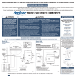
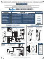
READ COMPLETE SAFETY INSTRUCTIONS AND INSTALLATION TEMPLATE BEFORE STARTING INSTALLATION
FURNISHED ITEMS
Figure 1
Figure 2
Figure 3
Figure 4
24 VAC Transformer
Digital Humidifier Control
(Model 700 only)
Manual Humidifier Control
(Model 700M only)
Humidifier Control
Installation Instructions
Saddle Valve
Humidifier Installation Template
ITEMS NOT FURNISHED
Mounting screws
(sheet metal screws)
Water supply line (1 ⁄ 4” copper)
Drain line (1 ⁄ 2” I.D. hose)
Low voltage wire
Model 50 Current Sensing Relay
(if required)
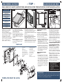
1. Detach the cover assembly by
lifting the latch at the bottom.
Remove the Water Panel®
evaporator assembly by grasping
at top and tipping out. See Figure 1.
2. Position template on supply
plenum. Make sure template is
level. Allow clearance for drain line
and for servicing. See “Installation
Options” on opposite side for
position relative to cooling coil.
90-923
90-924
90-925
5. Insert Water Panel Evaporator
Trace template outline. Cut 14-3/4”
wide x 14-5/16” high opening. Avoid
injury from sharp edges.
assembly into base. Make sure bottom of
scale control insert (5) is over drain
opening. Snap top of evaporator assembly
into base.
3. Position base (2) in duct opening
top-first so hooks engage sheet metal
at top. See Figure 2. Insert bottom of
base and slide down to engage hooks
at bottom.
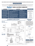
6. Control installation and wiring.
Disconnect electrical power to furnace
before wiring control. In order for
humidifier to operate, furnace must be on
and RH must be below set-point of control.
Wiring diagrams illustrate recommended
method of detecting furnace operation.
4. Rotate swing locks to secure base
to duct. See Figure 3. Fasten base to
duct using 4 sheet metal screws in
holes provided.
PARTS LIST
1. Front Cover
2. Base
3. Orifice Plate
4. Motor Mount Bridge
5. Scale Control Insert
6. Water Panel Evaporator
7. Water Distribution Tray
8. Fan Blade
9. Motor
16
15
6
3
2
Manual Control can be mounted in
return duct or on wall in living space.
Knob and cover must be removed to
mount control. See wiring diagram for
24V control connections.
• For return duct mounting, position
template in convenient location on duct.
Avoid injury from sharp edges when
cutting opening. Make sure foam
gasket is in place and secure control to
duct using 2 screws in holes provided.
• For wall-mount, select location that
will not be affected by drafts or heat
sources. Remove and discard foam
gasket and secure control over wire
access opening using screws &
anchors provided.
7
17
MANUAL HUMIDIFIER CONTROL,
MODEL 700M:
10. Motor Mount Gasket
11. Control Relay
12. Power Cord
13. Strain Relief Bushing
14. Solenoid Valve
15. Connector Plug
16. Feed Tube
17. Nozzle
18. Relay Connector Plug
DIGITAL HUMIDIFIER CONTROL,
MODEL 700:
• Select location for control on return
duct. Drill 3/4” hole for sensor. Knob
and cover must be removed to mount
control. Place control on duct with RH
sensor extending into duct opening.
Make sure gasket is in place around
sensor cage. Secure control to duct
using 2 screws in openings provided.
8
5
4
18
14
• See wiring diagrams on template and
control instructions for 24 V control
connections.
10
9
13
12
7. Humidifier will function with cold,
hot, softened or unsoftened water.
Hot water (140°F max) is strongly
recommended to provide maximum
evaporative capacity. Saddle valve
provided may be used to tap into water
supply. See installation instructions on
saddle valve package. Saddle valve is
designed to be fully opened or closed.
Do not use to regulate flow.
8. Run 1/4” copper tubing from saddle
valve to solenoid valve. DOUBLE-WRENCH
TO PREVENT LEAKING. See Figure 4.
9. INSTALL DRAIN IN ACCORDANCE
WITH LOCAL CODES. Run 1/2” I.D. hose
from drain spud to floor drain. Make
sure drain has constant downward
slope and is not kinked. Do not overtighten hose clamp onto drain spud. Do
not use solvent adhesive on drain spud.
10. Check humidifier operation. Open
saddle valve and turn control to highest
setting. Turn on furnace. Allow
humidifier to run until water flows from
drain. Make sure all electrical
connections are secure and all
plumbing connections are water-tight.
Set control to proper setting.
NOTE: BEFORE LEAVING THE
JOB SITE, MAKE SURE:
1. Saddle valve is fully open.
2. All plumbing connections are
watertight.
3. Humidifier functions properly.
11
1
TEMPLATE MUST BE LEVEL
90-926
90-1244
IMPORTANT! Be sure owner’s manual containing instructions for operation
and warranty information is given to owner in order to avoid unnecessary calls.
Warranty is void unless humidifier is installed by qualified heating and air conditioning
contractor due to possible misapplication of product.
10008976 B2205118A 4.10