1
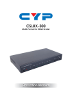
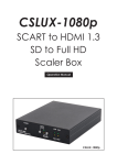
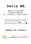
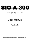
CSLUX-300I
Digital Video Scaler
Operation Manual
DISCLAIMERS
The information in this manual has been carefully checked and is
believed to be accurate. Cypress Technology assumes no
responsibility for any infringements of patents or other rights of third
parties which may result from its use.
Cypress Technology assumes no responsibility for any inaccuracies
that may be contained in this document. Cypress also makes no
commitment to update or to keep current the information contained
in this document.
Cypress Technology reserves the right to make improvements to this
document and/or product at any time and without notice.
COPYRIGHT NOTICE
No part of this document may be reproduced, transmitted,
transcribed, stored in a retrieval system, or any of its part translated
into any language or computer file, in any form or by any means—
electronic, mechanical, magnetic, optical, chemical, manual, or
otherwise—without express written permission and consent from
Cypress Technology.
© Copyright 2011 by Cypress Technology.
All Rights Reserved.
Version VR1.0 November 2011
TRADEMARK ACKNOWLEDGMENTS
All products or service names mentioned in this document may be
trademarks of the companies with which they are associated.
SAFETY PRECAUTIONS
Please read all instructions before attempting to unpack, install or
operate this equipment and before connecting the power supply.
Please keep the following in mind as you unpack and install this
equipment:
•
Always follow basic safety precautions to reduce the risk of fire,
electrical shock and injury to persons.
•
To prevent fire or shock hazard, do not expose the unit to rain,
moisture or install this product near water.
•
Never spill liquid of any kind on or into this product.
•
Never push an object of any kind into this product through any
openings or empty slots in the unit, as you may damage parts
inside the unit.
•
Do not attach the power supply cabling to building surfaces.
•
Use only the supplied power supply unit (PSU). Do not use the PSU
if it is damaged.
•
Do not allow anything to rest on the power cabling or allow any
weight to be placed upon it or any person walk on it.
•
To protect the unit from overheating, do not block any vents or
openings in the unit housing that provide ventilation and allow for
sufficient space for air to circulate around the unit.
REVISION HISTORY
VERSION NO.
DATE DD/MM/YY SUMMARY OF CHANGE
VR0
13/11/12
Preliminary Release
VR1
18/12/12
Add D-Sub to RCA adaptor
VR2
11/01/13
Add support Timing chart and protocol
CONTENTS
1. Introduction............................................ 1
2. Applications ........................................... 1
3. Package Contents ................................ 1
4. System Requirements............................ 1
5. Features .................................................. 2
6. Operation Controls and Functions....... 3
6.1 Front Panel ........................................ 3
6.2 Rear Panel......................................... 4
6.3 Remote Control................................ 6
6.4 RS-232 Protocols ............................... 7
6.5 RS-232 Commands........................... 8
6.6 OSD MENU....................................... 10
7. Connection and Installation............... 12
8. Specifications ...................................... 13
1. INTRODUCTION
The Digital Video Scaler has CV, SV, HD, Component, PC, HDMI and
SDI inputs and can scale the signal into HDMI, VGA with audio output
ports plus a SDI loop out. This high performance digital video scaler
supports HDMI output resolution up to 1080p /WUXGA and Analog
Digital Conversion (ADC) & Digital Analog Conversion (DAC) allowing
a wide range of AV signal to be insert to a high-Definition signal and
displaying. Further, with OSD, remote, RS-232 and on-panel controls
that makes whole for this Digital Video Scaler a friendly using device.
2. APPLICATIONS
• Lecture hall
• Meeting room
• Conference hall
3. PACKAGE CONTENTS
• Digital Video Scaler
• Remote Control (CR-117)
• D-Sub to RCA adaptor cable
• Power Adaptor
• Operation Manual
4. SYSTEM REQUIREMENTS
Input source equipments such as Blu-ray/DVD players or SDI camera,
output display and amplifier or speaker and connection cables.
5. FEATURES
• Supports multi AV inputs to HDMI or PC/HD outputs
• Supports EDID and HDCP
• Supports 3D de-interlace, noise reduction and 3D Comb filter
• Supports frame rate conversion
• Supports SDI loop out
• SDI peration at 2.970Gb/s, 2.970/1.001Gb/s, 1.485Gb/s,
1.485/1.001Gb/s and 270 Mb/s
• Supports SMPTE 425M (Level A and Level B), SMPTE 424M, SMPTE
292M, SMPTE 259M-C
• Supports signal input and output distanes of up to 300m for SD
signals, 200m for HD signals and 100m for 3G signals
Note: 1. SDI cable distance tested with belden 1694A. Operating
distances may be very if used with cables of different specifications.
6
6. OPERATION CONTROLS AND FUNCTIONS
6.1 Front Panel
CSLUX-300I DIGITAL VIDEO SCALER
XGA
POW ER
IR
INPUT
CV
SV
COMP
PC
HDMI 1
HDMI 2
SDI
ME NU
-
+
ENTER
720P
1
2
3
4
5
6
1 POWER & LED:
Press this button to switch ON or set the device to standby mode.
Once the device is connected with power supply the LED will
illuminate and the device will switch to ON automatically.
2 IR:
This IR window receives only the IR signal from the remote control
included in the package.
3 INPUT button and LEDs:
Press this button sequentially to switch in between the input sources
rotationally. LED will illuminate accordingly to the selected input
source.
4 MENU:
Press this button to enter into the OSD menu.
5 -/+:
Press these buttons to scrolled down and up in the OSD selection.
6 ENTER:
Press this button to confirm the selection. Press this button together
with + button to switch output to XGA instantly or with - button to
switch output to 720p instantly.
7
6.2 Rear Panel
2
3
4
5
6
RS232
OPTICAL
OPTICAL
SERVICE 1
SERVICE 2
L/R
R
L/R
PC/HD
SDI
LOOP OUTPUT
HDMI
L
CV
R
L
DC 5V
SDI
PC
HDMI 1
HDMI 2
Cr/Pr
Cb/Pb
Y
SV
R
L
1
7
1 OUTPUT:
L/R: Connect to speaker or amplifier for audio output in stereo
format.
HDMI: Connect to HDMI display or amplifier for video or video and
audio display.
OPTICAL: Connect to speaker or amplifier for audio output in
digital format.
PC/HD: Connect to monitor/display for video output display. For
HD output,use D-Sub 9pin to 3 RCA adaptor cable for output HD
timing from 480p~1080p.
2 SERVICE 1:
Reserved for factory use only.
3 SDI LOOP OUTPUT:
Connect to SDI display or SDI extender for instant SDI input signal
display or extending the SDI signal to further area.
4 RS-232:
Connect with PC/NB and use RS-232 command to control the
device.
5 SERVICE 2:
Reserved for factory use only.
6 INPUT:
SDI: Connect to SDI camera or other SDI source equipment for
both video and audio signal sending.
HDMI 1: Connect to HDMI source equipment such as Blu-ray/DVD
player for both video and audio signal sending.
8
HDMI 2: Connect to HDMI source equipment such as Blu-ray/DVD
player for both video and audio signal sending.
L/R: Connect to source equipment’s L/R output with 3.5Ø phone
jack for audio signal sending.
PC/HD: Connect with PC/NB source equipment for video signal
input with D-Sub 15pin cable.
OPTICAL: Connect to source equipment’s optical output for audio
signal sending.
YCbCr/HDPbPr + L/R: Connect to source equipment such as video/
DVD player for both video and audio signal sending.
CV + L/R: Connect to source equipment such as video/DVD player
for both video and audio signal sending.
SV + L/R: Connect to source equipment such as video/DVD player
for both video and audio signal sending.
7 DC 5V:
Plug the power adaptor included in the package and connect it
to the AC wall outlet for power supply.
9
6.3 Remote Control
1 INPUT: Press this button sequentially
to switch in between the input
sources rotationally. LED will
illuminate accordingly to the
selected input source.
INPUT
2
3
CV
SV
COMP
PC
HDMI 1
HDMI 2
2 POWER: Press this button to switch
ON or set the device to standby
mode. Once the device is
connected with power supply.
POWER
1
SDI
4
EXIT
MENU
5
3 CV/SV/COMP/PC/HDMI1/HDMI2/
SDI: Press these hot keys to switch
input source instantly.
OK
6
AUTO
ADJUST
RESET
4 EXIT: Press this button to exit the
menu or the current selection under
OSD.
7
8
5 MENU: Press this button to enter into
the OSD menu.
6 RESET: Press this button to set the
device back into the factory default
setting.
CR-117
7 AUTO ADJUST: Press this button when output image is not fitting the
display's screen perfectly. The device will auto adjust the image to
full screen.
8 OK & ▲▼◄►: Press OK to confirm the selection or press the arrow
buttons to scrolled in the OSD selections.
10
6.4 RS-232 Protocols
CSLUX-300I
Remote Control
PIN
Assignment
PIN
Assignment
1
NC
1
NC
2
Tx
2
Rx
3
Rx
3
Tx
4
NC
4
NC
5
GND
5
GND
6
NC
6
NC
7
NC
7
NC
8
NC
8
NC
9
NC
9
NC
Baud Rate: 9600 bps
Data bit: 8 bits
Parity: None
Flow Control: None
Stop Bit: 1
11
►
◄
6.5 RS-232 Commands
Command
Description
iJL
Start RS-232
S SOURCE 0~6
Select input source
R SOURCE
Inquire input source
S OUTPUT 1~25
Select output timing
R OUTPUT
Inquire output timing
Contents
SDI(0) / HDMI1(1) /
HDMI2(2) / YPBPR(3) /
VIDEO(4) / SVIDEO(5)/
PC(6)
RGB Encoded, 60 Hz:
640*480(1)/800*600(2)/
1024*768(3)/1280*768(4)/
1360*768(5)/1280*720(6)/
1280*800(7)/1280*1024(8)/
1440*900(9)/1400*1050(10)/
1680*1050(11)/
1600*1200(12)1920*1080(13)/
1920*1200(16)/
YUV Encoded:
480p(17)/720p 60(18)/
1080p 60(19)/ 1080i 60(20)/
576p(22)/720p 50(23)/
1080p 50(24)/ 1080i 50(25)
S SIZE 0~6
Select output size
R SIZE
Inquire output size
S CONTRAST 0~60
Contrast Setting
R CONTRAST
Inquire contrast setting
S BRIGHTNESS 0~60
Brightness setting
R BRIGHTNESS
Inquire brightness setting
S HUE 0~60
Hue setting
R HUE
Inquire hue setting
OVERSCAN(0) / FULL(1) /
BEST FIT(2) / PAN SCAN(3)/
LETTER BOX(4) /UNSER 2(5)
/ UNDER 1(6)
S SATURATION 0~60 Saturation setting
R SATURATION
Inquire saturation setting
S SHARPNESS 0~30
Sharpness setting
12
R SHARPNESS
Inquire sharpness setting
S NR 0~3
Noise reduction setting
R NR
Inquire noise reduction
setting
S AUDIODELAY 0~3
Audio delay setting
R AUDIODELAY
Inquire audio delay
setting
S AUDIOMUTE 0/1
Audio mute setting
R AUDIOMUTE
Inquire audio mute
setting
S SDIAUDIO 0~3
SDI Audio CH setting
R SDIAUDIO
Inquire SDI audio
CH setting
S AUDIOSELECT 0/1 Audio input setting
OFF(0) / LOW (1) /
MIDDLE(2) / HIGH(3)
OFF(0) / 40ms (1) /
110ms(2) / 150ms(3)
ON(0) / MUTE(1)
CH1CH2(0), CH3CH4(1)
CH5CH6(2), CH7CH8(3)
R AUDIOSELECT
Inquire audio input
setting
Analog (0)
Optical (1) at CV, SV,
YPbPr, PC
S KEY LOCK 0/1
Key lock setting
ENABLE(0) / DISABLE(1)
R KEY LOCK
Inquire key lock setting
FW
Firmware checking
S RESET 1
Pre-reset
S POWER 0/1
Power Setting
R POWER
Inquire Power Setting
EXIT
Exit
OFF (0) / ON (1)
1) iJL command must first be insert before starting using RS-232
command to control the device. This command is CASE-SENSITIVE.
Other RS-232 command will be not executed unless followed with a
CR+LF (Carriage Ret + Line Feed) and commands are CASEINSENSITIVE.
2)Audio delay supports only on analog L/R output.
3)When HDMI input is with HDCP, PC/HD will output no image.
4)Digital Audio supprts LPCM 2CH only therefore, please ensure source
input audio is sending LPCM 2CH's audio signal in order to
avoidunceccessary audio noise.
13
6.6 OSD MENU
1st Layer
2nd Layer
OUTPUT
DISPLAY
SIZE (VIDEO mode
only)
MODE INFO
PC (PC mode only)
3rd Layer
640x480 60
800x600 60
1024x768 60
1280x768 60
1360x768 60
1280x720 60
1280x800 60
1280x1024 60
1440x900 60
1400x1050 60
1680x1050 60
1600x1200 60
1920x1080 60
1920x1200 60
720X480P 60
1280X720P 60
1920X1080I 60
1920X1080P 60
720X576P 50
1280X720P 50
1920X1080I 50
1920X1080P 50
OVER SCAN
FULL
BEST FIT
PAN SCAN
LETTER BOX
UNDER 2
UNDER 1
OFF
INFO
ON
AUTO SETUP
H_POSITION
V_POSITION
PHASE
CLOCK
4th Layer
WXGA/XGA
XGA
WXGA
RESET
14
COLOR
COLOR
CONTRAST
BRIGHTNESS
HUE
SATURATION
SHARPNESS
NR.
AUDIO
VOLUME
DELAY
SOUND
SDI AUDIO
AUDIO SELECT
(CV, SV, YpbPr, PC
only)
R
G
B
R OFFSET
G OFFSET
B OFFSET
0~60
30
0~60
30
0~60
30
0~60
30
0~30
0
OFF
LOW
MIDDLE
HIGH
0~100
OFF
40mS
110mS
150mS
ON
MUTE
CH1 – CH2
CH3 – CH4
CH5 – CH6
CH7 – CH8
ANALOG
SPDIF
FACTORY RESET
SETUP
KEY LOCK
POWER SAVE
INFORMATION
INPUT
OUTPUT
REVISION
OFF
ON
OFF
ON
Bold characters are Factory default setting.
15
7. CONNECTION AND INSTALLATION
AVR with Optical Input
Set-top Box or DVD Player
RS232
OPTIC AL
OPTIC AL
SERVICE 1
SERVICE 2
L/R
R
L/R
PC/ HD
SDI
LOOP OUTPUT
HDMI
Composite video and stereo
audio from DVD player
CV
L
R
L
DC 5V
SDI
PC
HDMI 1
HDMI 2
Cr/Pr
Cb/Pb
Y
SV
R
L
Camcorder
S-Video and stereo audio
from Blu-ray player
SDI Monitor
Component and stereo audio
from DVD player
Monitor with 3.5 mm
audio input speaker
PC
TV or Monitor
16
8. SPECIFICATIONS
Input Port
1 x Composite,
1 x S-Video,
1 x Component, YcbCr or YPbPr
1 x PC/HD,
2 x HDMI w/HDCP
1 SD/HD/3G-SDI,
1 x Optical, LPCM, 2CH
4 x L/R ,
1 x USB (service only),
1 x HP Jack (service only),
1 x RS-232 (Control Only)
Output Port
1 x HDMI,
1 x PC/HD,
1 x SDI (Loop out),
1 x Optical, 1 x L/R
Supports Input Resolution
Supports Output Resolution
COMP: YCbCr 625i 50 Hz
YPbPr 480i, 480p, 720p,
1080i, 1080p, all 60 Hz
PC
: up to WUXGA 60 Hz
HDMI : up to 1080p 60 Hz, 12 bit
N°14 timings RGB encoded; All 60 Hz
From VGA to UXGA; 1920x1080; WUXGA
N°8 Timing YUV encoded:
480p, 720p, 1080i, 1080p 60 Hz
576p, 720p, 1080i, 1080p 50 Hz
Power Supply
5V/3A DC (US/EU standards, CE/FCC/
Dimensions (mm)
UL certified)
320mm(W) x 182mm(D) x 44mm(H)
Weight(g)
1600
Chassis Material
Metal
Silkscreen Color
Black
17
Operating Temperature
0˚C ~ 40˚C / 32 ˚F ~ 104 ˚F
Storage Temperature
-20˚C ~ 60˚C / -4 ˚F ~ 140 ˚F
Relative Humidity
20 ~ 90% RH (non-condensing)
Power Consumption(W)
10.5
18
CYPRESS TECHNOLOGY CO., LTD
Home page: http://www.cypress.com.tw
20120820 MPM-CSLUX300I
CSLUX-300I
Digital Video Scaler
Operation Manual
DISCLAIMERS
The information in this manual has been carefully checked and is
believed to be accurate. Cypress Technology assumes no
responsibility for any infringements of patents or other rights of third
parties which may result from its use.
Cypress Technology assumes no responsibility for any inaccuracies
that may be contained in this document. Cypress also makes no
commitment to update or to keep current the information contained
in this document.
Cypress Technology reserves the right to make improvements to this
document and/or product at any time and without notice.
COPYRIGHT NOTICE
No part of this document may be reproduced, transmitted,
transcribed, stored in a retrieval system, or any of its part translated
into any language or computer file, in any form or by any means—
electronic, mechanical, magnetic, optical, chemical, manual, or
otherwise—without express written permission and consent from
Cypress Technology.
© Copyright 2011 by Cypress Technology.
All Rights Reserved.
Version VR1.0 November 2011
TRADEMARK ACKNOWLEDGMENTS
All products or service names mentioned in this document may be
trademarks of the companies with which they are associated.
SAFETY PRECAUTIONS
Please read all instructions before attempting to unpack, install or
operate this equipment and before connecting the power supply.
Please keep the following in mind as you unpack and install this
equipment:
•
Always follow basic safety precautions to reduce the risk of fire,
electrical shock and injury to persons.
•
To prevent fire or shock hazard, do not expose the unit to rain,
moisture or install this product near water.
•
Never spill liquid of any kind on or into this product.
•
Never push an object of any kind into this product through any
openings or empty slots in the unit, as you may damage parts
inside the unit.
•
Do not attach the power supply cabling to building surfaces.
•
Use only the supplied power supply unit (PSU). Do not use the PSU
if it is damaged.
•
Do not allow anything to rest on the power cabling or allow any
weight to be placed upon it or any person walk on it.
•
To protect the unit from overheating, do not block any vents or
openings in the unit housing that provide ventilation and allow for
sufficient space for air to circulate around the unit.
REVISION HISTORY
VERSION NO.
DATE DD/MM/YY SUMMARY OF CHANGE
VR0
13/11/12
Preliminary Release
VR1
18/12/12
Add D-Sub to RCA adaptor
VR2
11/01/13
Add support Timing chart and protocol
CONTENTS
1. Introduction............................................ 1
2. Applications ........................................... 1
3. Package Contents ................................ 1
4. System Requirements............................ 1
5. Features .................................................. 2
6. Operation Controls and Functions....... 3
6.1 Front Panel ........................................ 3
6.2 Rear Panel......................................... 4
6.3 Remote Control................................ 6
6.4 RS-232 Protocols ............................... 7
6.5 RS-232 Commands........................... 8
6.6 OSD MENU....................................... 10
7. Connection and Installation............... 12
8. Specifications ...................................... 13
1. INTRODUCTION
The Digital Video Scaler has CV, SV, HD, Component, PC, HDMI and
SDI inputs and can scale the signal into HDMI, VGA with audio output
ports plus a SDI loop out. This high performance digital video scaler
supports HDMI output resolution up to 1080p /WUXGA and Analog
Digital Conversion (ADC) & Digital Analog Conversion (DAC) allowing
a wide range of AV signal to be insert to a high-Definition signal and
displaying. Further, with OSD, remote, RS-232 and on-panel controls
that makes whole for this Digital Video Scaler a friendly using device.
2. APPLICATIONS
• Lecture hall
• Meeting room
• Conference hall
3. PACKAGE CONTENTS
• Digital Video Scaler
• Remote Control (CR-117)
• D-Sub to RCA adaptor cable
• Power Adaptor
• Operation Manual
4. SYSTEM REQUIREMENTS
Input source equipments such as Blu-ray/DVD players or SDI camera,
output display and amplifier or speaker and connection cables.
5. FEATURES
• Supports multi AV inputs to HDMI or PC/HD outputs
• Supports EDID and HDCP
• Supports 3D de-interlace, noise reduction and 3D Comb filter
• Supports frame rate conversion
• Supports SDI loop out
• SDI peration at 2.970Gb/s, 2.970/1.001Gb/s, 1.485Gb/s,
1.485/1.001Gb/s and 270 Mb/s
• Supports SMPTE 425M (Level A and Level B), SMPTE 424M, SMPTE
292M, SMPTE 259M-C
• Supports signal input and output distanes of up to 300m for SD
signals, 200m for HD signals and 100m for 3G signals
Note: 1. SDI cable distance tested with belden 1694A. Operating
distances may be very if used with cables of different specifications.
6
6. OPERATION CONTROLS AND FUNCTIONS
6.1 Front Panel
CSLUX-300I DIGITAL VIDEO SCALER
XGA
POW ER
IR
INPUT
CV
SV
COMP
PC
HDMI 1
HDMI 2
SDI
ME NU
-
+
ENTER
720P
1
2
3
4
5
6
1 POWER & LED:
Press this button to switch ON or set the device to standby mode.
Once the device is connected with power supply the LED will
illuminate and the device will switch to ON automatically.
2 IR:
This IR window receives only the IR signal from the remote control
included in the package.
3 INPUT button and LEDs:
Press this button sequentially to switch in between the input sources
rotationally. LED will illuminate accordingly to the selected input
source.
4 MENU:
Press this button to enter into the OSD menu.
5 -/+:
Press these buttons to scrolled down and up in the OSD selection.
6 ENTER:
Press this button to confirm the selection. Press this button together
with + button to switch output to XGA instantly or with - button to
switch output to 720p instantly.
7
6.2 Rear Panel
2
3
4
5
6
RS232
OPTICAL
OPTICAL
SERVICE 1
SERVICE 2
L/R
R
L/R
PC/HD
SDI
LOOP OUTPUT
HDMI
L
CV
R
L
DC 5V
SDI
PC
HDMI 1
HDMI 2
Cr/Pr
Cb/Pb
Y
SV
R
L
1
7
1 OUTPUT:
L/R: Connect to speaker or amplifier for audio output in stereo
format.
HDMI: Connect to HDMI display or amplifier for video or video and
audio display.
OPTICAL: Connect to speaker or amplifier for audio output in
digital format.
PC/HD: Connect to monitor/display for video output display. For
HD output,use D-Sub 9pin to 3 RCA adaptor cable for output HD
timing from 480p~1080p.
2 SERVICE 1:
Reserved for factory use only.
3 SDI LOOP OUTPUT:
Connect to SDI display or SDI extender for instant SDI input signal
display or extending the SDI signal to further area.
4 RS-232:
Connect with PC/NB and use RS-232 command to control the
device.
5 SERVICE 2:
Reserved for factory use only.
6 INPUT:
SDI: Connect to SDI camera or other SDI source equipment for
both video and audio signal sending.
HDMI 1: Connect to HDMI source equipment such as Blu-ray/DVD
player for both video and audio signal sending.
8
HDMI 2: Connect to HDMI source equipment such as Blu-ray/DVD
player for both video and audio signal sending.
L/R: Connect to source equipment’s L/R output with 3.5Ø phone
jack for audio signal sending.
PC/HD: Connect with PC/NB source equipment for video signal
input with D-Sub 15pin cable.
OPTICAL: Connect to source equipment’s optical output for audio
signal sending.
YCbCr/HDPbPr + L/R: Connect to source equipment such as video/
DVD player for both video and audio signal sending.
CV + L/R: Connect to source equipment such as video/DVD player
for both video and audio signal sending.
SV + L/R: Connect to source equipment such as video/DVD player
for both video and audio signal sending.
7 DC 5V:
Plug the power adaptor included in the package and connect it
to the AC wall outlet for power supply.
9
6.3 Remote Control
1 INPUT: Press this button sequentially
to switch in between the input
sources rotationally. LED will
illuminate accordingly to the
selected input source.
INPUT
2
3
CV
SV
COMP
PC
HDMI 1
HDMI 2
2 POWER: Press this button to switch
ON or set the device to standby
mode. Once the device is
connected with power supply.
POWER
1
SDI
4
EXIT
MENU
5
3 CV/SV/COMP/PC/HDMI1/HDMI2/
SDI: Press these hot keys to switch
input source instantly.
OK
6
AUTO
ADJUST
RESET
4 EXIT: Press this button to exit the
menu or the current selection under
OSD.
7
8
5 MENU: Press this button to enter into
the OSD menu.
6 RESET: Press this button to set the
device back into the factory default
setting.
CR-117
7 AUTO ADJUST: Press this button when output image is not fitting the
display's screen perfectly. The device will auto adjust the image to
full screen.
8 OK & ▲▼◄►: Press OK to confirm the selection or press the arrow
buttons to scrolled in the OSD selections.
10
6.4 RS-232 Protocols
CSLUX-300I
Remote Control
PIN
Assignment
PIN
Assignment
1
NC
1
NC
2
Tx
2
Rx
3
Rx
3
Tx
4
NC
4
NC
5
GND
5
GND
6
NC
6
NC
7
NC
7
NC
8
NC
8
NC
9
NC
9
NC
Baud Rate: 9600 bps
Data bit: 8 bits
Parity: None
Flow Control: None
Stop Bit: 1
11
►
◄
6.5 RS-232 Commands
Command
Description
iJL
Start RS-232
S SOURCE 0~6
Select input source
R SOURCE
Inquire input source
S OUTPUT 1~25
Select output timing
R OUTPUT
Inquire output timing
Contents
SDI(0) / HDMI1(1) /
HDMI2(2) / YPBPR(3) /
VIDEO(4) / SVIDEO(5)/
PC(6)
RGB Encoded, 60 Hz:
640*480(1)/800*600(2)/
1024*768(3)/1280*768(4)/
1360*768(5)/1280*720(6)/
1280*800(7)/1280*1024(8)/
1440*900(9)/1400*1050(10)/
1680*1050(11)/
1600*1200(12)1920*1080(13)/
1920*1200(16)/
YUV Encoded:
480p(17)/720p 60(18)/
1080p 60(19)/ 1080i 60(20)/
576p(22)/720p 50(23)/
1080p 50(24)/ 1080i 50(25)
S SIZE 0~6
Select output size
R SIZE
Inquire output size
S CONTRAST 0~60
Contrast Setting
R CONTRAST
Inquire contrast setting
S BRIGHTNESS 0~60
Brightness setting
R BRIGHTNESS
Inquire brightness setting
S HUE 0~60
Hue setting
R HUE
Inquire hue setting
OVERSCAN(0) / FULL(1) /
BEST FIT(2) / PAN SCAN(3)/
LETTER BOX(4) /UNSER 2(5)
/ UNDER 1(6)
S SATURATION 0~60 Saturation setting
R SATURATION
Inquire saturation setting
S SHARPNESS 0~30
Sharpness setting
12
R SHARPNESS
Inquire sharpness setting
S NR 0~3
Noise reduction setting
R NR
Inquire noise reduction
setting
S AUDIODELAY 0~3
Audio delay setting
R AUDIODELAY
Inquire audio delay
setting
S AUDIOMUTE 0/1
Audio mute setting
R AUDIOMUTE
Inquire audio mute
setting
S SDIAUDIO 0~3
SDI Audio CH setting
R SDIAUDIO
Inquire SDI audio
CH setting
S AUDIOSELECT 0/1 Audio input setting
OFF(0) / LOW (1) /
MIDDLE(2) / HIGH(3)
OFF(0) / 40ms (1) /
110ms(2) / 150ms(3)
ON(0) / MUTE(1)
CH1CH2(0), CH3CH4(1)
CH5CH6(2), CH7CH8(3)
R AUDIOSELECT
Inquire audio input
setting
Analog (0)
Optical (1) at CV, SV,
YPbPr, PC
S KEY LOCK 0/1
Key lock setting
ENABLE(0) / DISABLE(1)
R KEY LOCK
Inquire key lock setting
FW
Firmware checking
S RESET 1
Pre-reset
S POWER 0/1
Power Setting
R POWER
Inquire Power Setting
EXIT
Exit
OFF (0) / ON (1)
1) iJL command must first be insert before starting using RS-232
command to control the device. This command is CASE-SENSITIVE.
Other RS-232 command will be not executed unless followed with a
CR+LF (Carriage Ret + Line Feed) and commands are CASEINSENSITIVE.
2)Audio delay supports only on analog L/R output.
3)When HDMI input is with HDCP, PC/HD will output no image.
4)Digital Audio supprts LPCM 2CH only therefore, please ensure source
input audio is sending LPCM 2CH's audio signal in order to
avoidunceccessary audio noise.
13
6.6 OSD MENU
1st Layer
2nd Layer
OUTPUT
DISPLAY
SIZE (VIDEO mode
only)
MODE INFO
PC (PC mode only)
3rd Layer
640x480 60
800x600 60
1024x768 60
1280x768 60
1360x768 60
1280x720 60
1280x800 60
1280x1024 60
1440x900 60
1400x1050 60
1680x1050 60
1600x1200 60
1920x1080 60
1920x1200 60
720X480P 60
1280X720P 60
1920X1080I 60
1920X1080P 60
720X576P 50
1280X720P 50
1920X1080I 50
1920X1080P 50
OVER SCAN
FULL
BEST FIT
PAN SCAN
LETTER BOX
UNDER 2
UNDER 1
OFF
INFO
ON
AUTO SETUP
H_POSITION
V_POSITION
PHASE
CLOCK
4th Layer
WXGA/XGA
XGA
WXGA
RESET
14
COLOR
COLOR
CONTRAST
BRIGHTNESS
HUE
SATURATION
SHARPNESS
NR.
AUDIO
VOLUME
DELAY
SOUND
SDI AUDIO
AUDIO SELECT
(CV, SV, YpbPr, PC
only)
R
G
B
R OFFSET
G OFFSET
B OFFSET
0~60
30
0~60
30
0~60
30
0~60
30
0~30
0
OFF
LOW
MIDDLE
HIGH
0~100
OFF
40mS
110mS
150mS
ON
MUTE
CH1 – CH2
CH3 – CH4
CH5 – CH6
CH7 – CH8
ANALOG
SPDIF
FACTORY RESET
SETUP
KEY LOCK
POWER SAVE
INFORMATION
INPUT
OUTPUT
REVISION
OFF
ON
OFF
ON
Bold characters are Factory default setting.
15
7. CONNECTION AND INSTALLATION
AVR with Optical Input
Set-top Box or DVD Player
RS232
OPTIC AL
OPTIC AL
SERVICE 1
SERVICE 2
L/R
R
L/R
PC/ HD
SDI
LOOP OUTPUT
HDMI
Composite video and stereo
audio from DVD player
CV
L
R
L
DC 5V
SDI
PC
HDMI 1
HDMI 2
Cr/Pr
Cb/Pb
Y
SV
R
L
Camcorder
S-Video and stereo audio
from Blu-ray player
SDI Monitor
Component and stereo audio
from DVD player
Monitor with 3.5 mm
audio input speaker
PC
TV or Monitor
16
8. SPECIFICATIONS
Input Port
1 x Composite,
1 x S-Video,
1 x Component, YcbCr or YPbPr
1 x PC/HD,
2 x HDMI w/HDCP
1 SD/HD/3G-SDI,
1 x Optical, LPCM, 2CH
4 x L/R ,
1 x USB (service only),
1 x HP Jack (service only),
1 x RS-232 (Control Only)
Output Port
1 x HDMI,
1 x PC/HD,
1 x SDI (Loop out),
1 x Optical, 1 x L/R
Supports Input Resolution
Supports Output Resolution
COMP: YCbCr 625i 50 Hz
YPbPr 480i, 480p, 720p,
1080i, 1080p, all 60 Hz
PC
: up to WUXGA 60 Hz
HDMI : up to 1080p 60 Hz, 12 bit
N°14 timings RGB encoded; All 60 Hz
From VGA to UXGA; 1920x1080; WUXGA
N°8 Timing YUV encoded:
480p, 720p, 1080i, 1080p 60 Hz
576p, 720p, 1080i, 1080p 50 Hz
Power Supply
5V/3A DC (US/EU standards, CE/FCC/
Dimensions (mm)
UL certified)
320mm(W) x 182mm(D) x 44mm(H)
Weight(g)
1600
Chassis Material
Metal
Silkscreen Color
Black
17
Operating Temperature
0˚C ~ 40˚C / 32 ˚F ~ 104 ˚F
Storage Temperature
-20˚C ~ 60˚C / -4 ˚F ~ 140 ˚F
Relative Humidity
20 ~ 90% RH (non-condensing)
Power Consumption(W)
10.5
18
CYPRESS TECHNOLOGY CO., LTD
Home page: http://www.cypress.com.tw
20120820 MPM-CSLUX300I