1
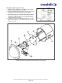
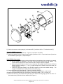
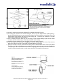
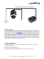
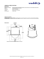
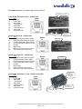
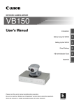
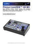
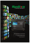
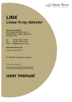
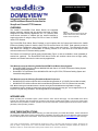
Installation and User Guide Camera and Electronic Products for Integrators DOMEVIEW™ Integrated Flush Mount Dome Systems and Flush Mount Dome Enclosures for Sony® and Canon® PTZ Cameras OVERVIEW: The Vaddio™ DomeVIEW Flush Mount Domes are integrated camera mounting systems that are attractive and easy to install. Designed for indoor security applications, the 7.3” (18.54cm) flush mount dome enclosure is outfitted with the internal brackets to support the option of using the Sony EVI-D70 or Canon VC-C50iR robotic PTZ cameras. Figure 1: Flush Mount Dome Enclosure shown with Smoke Tinted Dome (Clear is Standard, Smoked Tinted is Optional) The DomeVIEW Flush Mount Dome Package is sold complete with the Camera and features the Vaddio EZCamera Cabling System for both the Sony EVI-D70 and the Canon VC-C50iR. Both systems provide for fast and efficient installations using Cat-5e cabling for video, power and control. The enclosures are also sold without the camera to accommodate an existing camera to be used with the Flush Mount Dome enclosure without the EZ Camera cabling system. The Domes are formed from optical grade polycarbonate (Figure 1) and are available in clear (standard) or smoked tint (optional). The DomeVIEW Flush Mount Domes are excellent values that are high quality, attractive and durable solutions for indoor security applications. This Manual covers the following Vaddio DomeVIEW Flush Mount Dome Systems: DomeVIEW 50iR Flush Mount Dome 999-9000-050 with Canon VC-C50iR, EZCamera Cabling System and Internal Mounting Bracket DomeVIEW 70 Flush Mount Dome 999-9000-070 with Sony EVI-D70, EZCamera Cabling System and Internal Mounting Bracket This Manual covers the following Flush Mount Dome Enclosures: 998-9000-050 Flush Mount Dome with Internal Mounting Bracket for VC-C50iR (Camera Not Included) 998-9000-070 Flush Mount Dome with Internal Mounting Bracket for EVI-D70 (Camera Not Included) Note: When mounting the Flush Mount Dome in Acoustic ceiling tile, the 997-9000-000 Tile Support Brace is highly recommended in order to transfer the weight of the camera and enclosure into the ceiling grid. The Tile Support Brace is not required in a dry wall ceiling installation. The Tile Support Brace is sold separately. INTENDED USE: Before operating the DomeVIEW system, please read the entire manual thoroughly. The DomeVIEW Flush Mount systems were designed, built and tested for use indoors and with the provided power supply. The use of a power supply other than the one provided or outdoor operation has not been tested and could damage the electronics and/or create a potentially unsafe operating condition. SAVE THESE INSTRUCTIONS: The information contained in this manual will help you install and operate your Vaddio DomeVIEW. If these instructions are misplaced, Vaddio keeps copies of Specifications, Installation and User Guides and most pertinent product drawings for the Vaddio product line on the website. These documents can be downloaded from www.vaddio.com free of charge. ⓒ2011 Vaddio - DomeVIEW Systems - All Rights Reserved. Reproduction in whole or in part without written permission is prohibited. Specifications and pricing are subject to change without notice. Vaddio, DomeVIEW, EZCamera, Quick-Connect, WallVIEW, CeilingVIEW, EZCable and PowerRite are trademarks of Vaddio, Inc. All other trademarks are property of their respective owners. Document 341-443 Rev C1. IMPORTANT SAFEGUARDS: Read and understand all instructions before using. Do not operate the system if it has been dropped or damaged. In this case, a Vaddio technician must examine the product before operating. To reduce the risk of electric shock, do not immerse in water or other liquids and avoid extremely humid conditions. Use only the power supply (or power supplies) provided with the DomeVIEW systems. Use of any unauthorized power supply will void any and all warranties. Do not use “pass-thru” RJ-45 connectors during installation. standard RJ-45 connectors and test all terminated cables. Use only UNPACKAGING – SYSTEM COMPONENT LISTS Carefully remove all parts from the packaging. Unpack and identify the following parts for each product: 999-9000-050 DomeVIEW 50iR Flush Mount Dome System includes: QTY 1 1 3 1 3 2 2 1 1 1 1 1 1 1 1 Description Canon VC-C50iR PTZ camera Canon IR remote control 4.5” x .375 (114.3mm x 9.525mm) Hex shaped stand-offs 6” x 6” (15.24cm x 15.24cm) Camera mounting stage 8-32 x .5” Flat head screws (flush mount) 8-32 x .5” pan head screws Lock washers for pan head screws Plenum rated steel back can White twist and lock trim ring Clear dome bubble mounted to trim ring Conduit connector and nut Safety chain attachment plate 50 EZCamera Shoe (998-4411-001) Quick-Connect (998-1105-001) PowerRite Power Supply (451-2750-018) 999-9000-070 DomeVIEW 70 Flush Mount Dome System includes: QTY 1 1 3 1 3 1 1 4 2 1 1 1 1 1 1 1 1 Description Sony EVI-D70C/W PTZ camera (platinum white) Vaddio IR Remote Commander (for Sony cameras) 2.75” x .375 (69.85mm x 9.525mm) Hex shaped stand-offs 6” x 6” (15.24cm x 15.24cm) Camera mounting stage 8-32 x .5” Flat head screws (flush mount) 6” x 6” (15.24cm x 15.24cm) Camera mounting plate ¼”-20 x ½” Mounting screw (to attach camera to mounting plate) 8-32 x .5” pan head screws #8 Lock washers for pan head screws Plenum rated steel back can White twist and lock trim ring Clear dome bubble mounted to trim ring Conduit connector and nut Safety chain attachment plate 70 EZCamera Shoe (998-2211-004) Quick-Connect (998-1105-001) PowerRite Power Supply (998-2750-018) Vaddio DomeVIEW Flush Mount Dome Installation and User Guide - Document 341-443 Rev C1 Page 2 of 12 Flush Mount Dome Enclosures Only (Cameras Not Included) The Flush Mount Dome Enclosures are for use with existing or standard Sony EVI-D70 and Canon VCC50iR. The Dome enclosures can also be used with the Vaddio Standard EZCamera Cable system for the EVI-D70 or the VC-C50i analog PTZ cameras. The dome enclosures without cameras are listed below: 998-9000-050 Flush Mount Dome Enclosure includes: QTY 1 1 1 1 1 3 1 3 2 2 Description Plenum rated steel back can White twist and lock trim ring Clear dome bubble mounted to trim ring Conduit connector and nut Safety chain attachment plate 4.5” x .375 (114.3mm x 9.525mm) Hex shaped stand-offs 6” x 6” (15.24cm x 15.24cm) Camera mounting stage 8-32 x .5” Flat head screws (flush mount) 8-32 x .5” pan head screws Lock washers for pan head screws 998-9000-070 Flush Mount Dome Enclosure includes: QTY 1 1 1 1 1 3 1 3 1 1 4 4 Description Plenum rated steel back can White twist and lock trim ring Clear dome bubble mounted to trim ring Conduit connector and nut Safety chain attachment plate 2.75” x .375 (69.85mm x 9.525mm) Hex shaped stand-offs 6” x 6” (15.24cm x 15.24cm) Camera mounting stage 8-32 x .5” Flat head screws (flush mount) 6” x 6” (15.24cm x 15.24cm) Camera mounting plate (attaches to camera) ¼”-20 x ½” Mounting screw (to attach camera to mounting plate) 8-32 x .5” pan head screws #8 Lock washers for pan head screws INSTALLATION INSTRUCTIONS for: DomeVIEW 50iR Flush Mount Dome System (999-9000-050) DomeVIEW 70 Flush Mount Dome System (999-9000-070) Flush Mount Dome Enclosures for: CanonVC-C50iR (998-9000-050) and Sony EVI-D70 (998-9000-070) Before Starting the Installation Before starting the installation of the Flush Mount Dome system, check above the ceiling where you plan to install the camera to make sure the area is clear and that there is adequate room for the Camera Enclosure. Make sure that the cabling required to operate the camera is brought to the point where the camera is to be installed. For cabling requirements, see the Cabling Requirements section. All above ceiling work must conform to local building codes and should be performed by qualified personnel. Vaddio DomeVIEW Flush Mount Dome Installation and User Guide - Document 341-443 Rev C1 Page 3 of 12 Step-by-Step Assembly Instructions: 1) Attach conduit connector to the back of the plenum rated back can with the provided lock nut. 2) Attach the Safety Bracket to the conduit connector to tie a safety line up to the building structure if required. 3) All Cabling must be run through this conduit connector either through conduit or plenum rated cables with all connectors inside the back can to retain the plenum rating of the dome enclosure. 4) Thread on the three hex shaped stand-offs (7) on to the studs in the bottom of the metal back can (8) (See Figures 3 and 4). Figure 2: Plenum Rated Back Can Assembly Figure 3: Exploded View of DomeVIEW Flush Mount Dome for Canon VC-C50iR Vaddio DomeVIEW Flush Mount Dome Installation and User Guide - Document 341-443 Rev C1 Page 4 of 12 Figure 4: Exploded View of DomeVIEW Flush Mount Dome for Sony EVI-D70 5) Attach the camera mounting stage (6) to the stand offs (7) with three 8-32 x .5” flat head screws (5). Canon VC-C50iR Camera only: 6) Attach the EZCamera Cabling Shoe (4 – Figure 3) to the Canon VC-C50iR. 7) Attach the camera (3) to the camera mounting stage (6) with two 8-32 x .5” pan head screws (2) and two #8 lock washers (see Figure 3). Skip to Step 12. Sony EVI-D70 Camera only: 8) Image Flip Switch, IR Select Switch and other Mode switches (set switches prior to powering up camera) a. Set the Image Flip dipswitch on the back of the EVI-D70 camera to the ON position. The camera will be inverted in the dome enclosure and the image needs to be flipped. b. When using the IR Remote control in an environment with multiple cameras, set the IR Select Switch frequency setting to 1, 2 or 3 to avoid having the IR remote control more than one camera at a time. c. Check the full-length manual for the EVI-D70 camera for other mode switch settings. The manual is available on the Vaddio website (www.vaddio.com). 9) Attach the EZCamera Cabling Shoe (4 – Figure 4) to the Sony EVI-D70. a. When mounting a Sony EVI-D70 without the EZCamera Cable System - skip this step. 10) Attach the Camera Base Plate (9) to the camera (3) with the provided ¼”-20 x .5” screw (10). 11) Attach the camera (3) and camera base plate (9) to the camera mounting stage (6) with four 8-32 x .5” pan head screws (2) and four #8 lock washers (see Figure 4). Vaddio DomeVIEW Flush Mount Dome Installation and User Guide - Document 341-443 Rev C1 Page 5 of 12 * Figure 5: Mounting the Flush Mount Enclosure Figure 6: Flush Mount Enclosure in the Ceiling *(Tile Support Bracket, 997-9000-000, is sold separately for use with acoustic ceiling tiles. This brace is not needed for hard/drywall ceilings.) 12) Cut an 8” (20.32cm) round hole in ceiling tile (D) or drywall ceiling (See Figure 5). 13) If mounting the enclosure in an acoustic ceiling tile, then the (C) Tile Support Brace (sold separately part # 997-9000-000) must be used to hold the weight of the dome enclosure on the back of the Tile Support Brace and distribute that weight into the ceiling grid. If mounting the enclosure in a drywall ceiling, then a support brace is not required. 14) Prior to installing the dome back box into the ceiling, pull the required cabling length into the conduit connector and into the back can to allow easy termination of the camera. 15) Install the Housing Assembly (E) into the ceiling tile or drywall ceiling (Figure 5). 16) Turn the clamp screw clock wise to engage the anchor clip (F) and tighten the Anchor Clips onto the back of the ceiling or the back of the ceiling Tile Support Brace (C) (Figure 5). 1) When the Camera is securely mounted to the ceiling, take the Dome Bubble and the Twist & Lock White Trim Ring, (1) in Figure 7, and twist it on to the dome enclosure (two hooks on the trim ring will slide over the two pegs on the metal enclosure and lock the trim ring and dome into place) to cover the camera. Be careful to position the safety tether to avoid contact with the PTZ mechanism of the camera. Figure 7: Attach the Dome Bubble (Clear is standard – smoke tinted is optional) and White Trim Ring. The assembly has a twist and lock attachment which provides a secure connection of the ring to the back can. Important Note: Tuck the safety tether inside the enclosure to avoid interference to the PTZ camera movement. Vaddio DomeVIEW Flush Mount Dome Installation and User Guide - Document 341-443 Rev C1 Page 6 of 12 EZCamera SYSTEM COMPONENTS The DomeVIEW Systems are built around either the Sony EVI-D70 (999-9000-070) or the Canon VC-C50iR (999-9000-050) and are shipped with the standard Quick-Connect, PowerRite and EZCamera Cabling Shoe. DomeVIEW 50iR Cabling Distances with Standard and Optional Power Supplies The DomeVIEW 50iR can transmit video up to 185 feet using the supplied 18 VDC PowerRite power supply, and from 185 feet to 275 feet using the optional 24 VDC PowerRite power supply (part# 451-2000-024). This EZ Camera Cabling system provides both S-video and composite video. DomeVIEW 70 Cabling Distances with Standard and Optional Power Supplies The DomeVIEW 70 can transmit video up to 200 feet using the supplied 18 VDC PowerRite power supply, and from 200 feet to 300 feet using the optional 24 VDC PowerRite power supply (part# 451-2000-024). This EZ Camera Cabling system provides both S-video and composite video. The EZCamera Cable Shoe for the Sony EVI-D70 and Canon VC-C50iR The EZCamera Cable Shoe attaches to the back of the Canon VC-C50iR camera and changes the native power, video and control connectors to RJ-45s for use with Cat. 5 cabling. The Shoe has a voltage regulator and transformers (baluns) to optimize the video signal for use over Cat. 5 cable. The RS-232C control cabling uses 5-wires to provide for bi-directional control signaling and daisy chain control of multiple cameras. Figure 8: The Canon VC-C50iR and Sony EVID70 are shown with the EZCamera Cabling Shoes attached. The RJ-45 connectors are: 1) Power/Video 2) RS-232 IN 3) RS-232 OUT Figure 9: EZCamera Cable Shoe for the DomeVIEW 70 shows RJ45 connections for Power/Video, RS-232 IN and RS-232 OUT on the top of the Shoe (upper image). The back of the Shoe (lower image) shows the connector labeling. See Appendix A for pin-out information. POWER VIDEO RS-232 IN RS-232 OUT Vaddio DomeVIEW Flush Mount Dome Installation and User Guide - Document 341-443 Rev C1 Page 7 of 12 For cabling distances using the standard and optional power supplies for the DomeVIEW 50iR and 70, see the previous page for additional information. RS-232 on Cat. 5e RS-232 OUT to next camera for daisy chain control CAMERA CONTROL For the DomeVIEW 50iR PTZ and DomeVIEW 70 PTZ Flush Mount Dome Systems, the RS-232 control programming information is in the technical manuals for the Sony EVI-D70 and Canon VC-C50iR PTZ which can be found on the Vaddio website (www.vaddio.com) under the TechNotes tab and under the PTZ Camera product grouping. Control system manufacturers’ also have programs readily available for these cameras to be used with their control systems (i.e. Crestron® and AMX®). Please contact those companies for the demo programs and for debugging of the programs that they provide. Both the DomeVIEW 50iR PTZ and the DomeVIEW 70 PTZ are shipped with IR remote controllers for camera control. The camera base with the IR window is recessed inside the dome enclosure and the acceptance angle of the IR control signaling is affected. The angle of acceptance for the IR remote control is narrower and more directional. Please take this into account when controlling the cameras with an IR remote. CABLING REQUIREMENTS For the DomeVIEW 70 and 50iR Flush Mount Dome that uses the EZCamera Cabling system, the cabling requirements are as follows: One (1) Cat. 5 Cable for Power/Video One (1) Cat. 5 Cable for RS-232 control input One (1) Cat 5 Cable for RS-232 control output for daisy chaining Sony or Canon Cameras Vaddio DomeVIEW Flush Mount Dome Installation and User Guide - Document 341-443 Rev C1 Page 8 of 12 GENERAL SPECIFICATIONS Mechanical: Recessed Housing: Dome: Trim Ring: Weight: Environment: Steel construction with black powder-coat finish Plenum rated; Meets UBC 4305-A Optical-grade polycarbonate White ABS plastic Dome only 4.4lbs (2Kg) Indoor Only Option Accessories: 997-9000-000 Tile Support Brace for mounting dome in 2’ x 2’ (61cm x 61cm) or 2’ x 4’ (61cm x 122cm) acoustic ceiling tiles 451-2000-024 PowerRite 24 VDC power supply (see page 7 for distances covered by each camera using 24 VDC supply) Dimensions: 7” Flat Side 8” Round 8.00 Dimensions in inches, reference conversion 1” = 2.54cm Vaddio DomeVIEW Flush Mount Dome Installation and User Guide - Document 341-443 Rev C1 Page 9 of 12 Warranty Information: (See Vaddio Warranty, Service and Return Policies posted on vaddio.com for complete details): Hardware* Warranty: One year limited warranty on all parts. Vaddio warrants this product against defects in materials and workmanship for a period of one year from the day of purchase from Vaddio. If Vaddio receives notice of such defects during the warranty period, they will, at their option, repair or replace products that prove to be defective. Please see Vaddio’s Service Terms and Conditions at vaddio.com for specific details and policies. Exclusions: The above warranty shall not apply to defects resulting from: improper or inadequate maintenance by the customer, customer applied software or interfacing, unauthorized modifications or misuse, operation outside the normal environmental specifications for the product, use of the incorrect power supply, improper extension of the power supply cable or improper site operation and maintenance. Vaddio Customer Service: Vaddio will test, repair, or replace the product or products without charge if the unit is under warranty and is found to be defective. If the product is out of warranty, Vaddio will test then repair the product or products. The cost of parts and labor charge will be estimated by a technician and confirmed by the customer prior to repair. All components must be returned for testing as a complete unit. Vaddio will not accept responsibility for shipment after it has left the premises. Vaddio Technical Support: Vaddio technicians will determine and discuss with the customer the criteria for repair costs and/or replacement. Vaddio Technical Support can be contacted through one of the following resources: e-mail support at [email protected] or online at www.vaddio.com. Return Material Authorization (RMA) Number : Before returning a product for repair or replacement, request an RMA from Vaddio’s technical support. Provide a technician with a return phone number, e-mail address, shipping address, and product serial numbers and describe the reason for repairs or returns as well as the date of purchase and proof of purchase. Include your assigned RMA number in all correspondence with Vaddio. Write your assigned RMA number on the outside of the box when returning the product. All products returned for credit are subject to a restocking charge without exception. Voided Warranty: The warranty does not apply if the original serial number has been removed or if the product has been disassembled or damaged through misuse, accident, modifications, or unauthorized repair. Cutting the power supply cable on the secondary side (low voltage side) to extend the power to the device (camera or controller) voids the warranty for that device. Shipping and Handling: Vaddio will not pay for inbound shipping transportation or insurance charges or accept any responsibility for laws and ordinances from inbound transit. Vaddio will pay for outbound shipping, transportation, and insurance charges for all items under warranty but will not assume responsibility for loss and/or damage by the outbound freight carrier. • If the return shipment appears damaged, retain the original boxes and packing material for inspection by the carrier. Contact your carrier immediately. Products Not Under Warranty: Payment arrangements are required before outbound shipment for all out of warranty products. *Vaddio manufactures its hardware products from parts and components that are new or equivalent to new in accordance with industry standard practices. Care and Cleaning Do not spill liquids in the product Keep this device away from food and liquid For smears or smudges on the product, wipe with a clean, soft cloth Do not use any abrasive chemicals. Operating and Storage Conditions: Do not store or operate the device under the following conditions: Temperatures above 40°C (104°F) or temperatures below 0°C (32°F) High humidity, condensing or wet environments In inclement weather or under severe vibration In swimming pools, waterfalls, outer space, bear caves or eagle’s nest Dry environments with an excess of static discharge Appendix 1: Vaddio Power, Video and Control Pin-outs Vaddio DomeVIEW Flush Mount Dome Installation and User Guide - Document 341-443 Rev C1 Page 10 of 12 For Vaddio Cameras: DomeVIEW 50iR and DomeVIEW 70 Power/Video Connector Power/Video Connection RJ-45 – Camera Shoe # Pins Power 1) Power (+) Video 2) Power GND 3) Video GND 4) Y (luminance) 5) Video GND 12345678 6) C (Chrominance) 7) Video GND 8) Composite Video Vaddio Camera Shoe Back View Top View RS-232 OUT RS-232 Connector IN – Camera Shoe # Pins 1) DTR (Sony® Daisy chain to DSR) 2) DSR (Sony Daisy chain from DTR) 3) CTS (Canon® Daisy chain to RTS) 4) RTS (Canon Daisy chain from CTS) 5) Unused 6) Digital GND 7) RXD (from TXD of control source) 8) TXD (to RXD of control source) RS-232 Connector Out – Camera Shoe # Pins 1) DSR (Sony Daisy chain from DTR) 2) DTR (Sony Daisy chain to DSR) 3) RTS (Canon Daisy chain from CTS) 4) CTS (Canon Daisy chain to RTS) 5) Unused 6) Digital GND 7) TXD (to RXD of control source) 8) RXD (from TXD of control source) RS-232 In RS-232 IN Power/Video Connector RS-232 IN 12345678 Vaddio Camera Shoe Back View RS-232 Out RS-232 OUT 12345678 Power/Video Connection – RJ-45 – Quick-Connect Box # Pins Power 1) Power + Video 2) Power GND 3) Video GND 4) Y (luminance) 5) Video GND 6) C (Chrominance) 12345678 7) Video GND 8) Composite Video Vaddio Camera Shoe Back View RJ-45 Power/Video Connector to Camera Shoe Top S-Video From Camera Power View Supply To Camera Shoe Composite Video From Camera Vaddio DomeVIEW Flush Mount Dome Installation and User Guide - Document 341-443 Rev C1 Page 11 of 12 9433 Science Center Drive ▪ Minneapolis, MN 55428 Toll Free: 800-572-2011 ▪ Phone: 763-971-4416 ▪ FAX: 763-971-4464 www.vaddio.com ©2011 Vaddio, All Rights Reserved. Reproduction in whole or in part without written permission is prohibited. Specifications and pricing are subject to change without notice. Vaddio, DomeVIEW, EZCamera, Quick-Connect, WallVIEW, CeilingVIEW, EZCable and PowerRite are trademarks of Vaddio, Inc. All other trademarks are property of their respective owners. Document 341-443 Rev C1. Vaddio DomeVIEW Flush Mount Dome Installation and User Guide - Document 341-443 Rev C1 Page 12 of 12