1
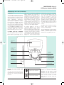
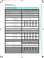
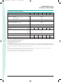
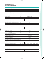
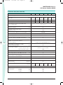
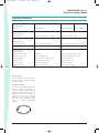
Tecnico-SIII-MG
10-11-2004
8:22
Pagina 3
MASTERGUARD Series S III
UPS Systems from 60 to 800 kVA
2 System description
2.2 Models Available
The Series SIII range shall include the
following three-phase input/output
models:
MODEL
Series SIII/60
Rating (kVA)
60
MODEL
Series SIII/250
Rating (kVA)
250
Series SIII/80
80
Series SIII/300
300
Series SIII/100
100
Series SIII/400
400
Series SIII/120
120
Series SIII/500
500
Series SIII/160
160
Series SIII/600
600
Series SIII/200
200
Series SIII/800
800
3 Device description
Series SIII is the result of an innovative
research and development programme
designed to offer users the most
reliable power supply at a minimum
cost.
3.1 Components
The UPS shall consist of the following
major components:
• Rectifier/battery charger/electronic
battery switch
• IGBT inverter
• Digital signal processor (DSP)
• Electronic static switch and reserve
supply
• Manual maintenance bypass switch
• Matching battery cubicles
3.2 Microprocessor control and
diagnostics
Operation and control of the UPS shall
be provided through the use of
microprocessor-controlled
logic.
Indications,
measurements
and
alarms,
together
with
battery
autonomy, shall be shown on an
illuminated, forty character liquid
crystal display (LCD). The procedures
for start up, shutdown and manual
transfer of the load to and from bypass
shall be explained in clear step-by-step
sequences on the LCD display.
3.3 Intelligent double conversion
operating modes
Series SIII shall adopt intelligent double
conversion technology which allows
the UPS to operate in double
conversion or digital interactive mode
according to the selected priority.
The UPS will operate as follows:
3.3.1 Double Conversion Mode
3.3.1.1 Normal
The UPS inverter continuously
supplies the critical AC load. The
rectifier/charger derives power from
the commercial AC source and
converts it into DC power for the
inverter
whilst
simultaneously
maintaining the battery in a fully
charged and optimum operational
condition (for more details see section
5.11 “Battery Management”). The
inverter converts the DC power into
clean and regulated AC power which is
supplied to the critical load through the
static transfer switch. The static switch
monitors and ensures that the inverter
tracks the reserve supply frequency.
This ensures that any automatic
transfer to the reserve supply (due to
an overload etc.) is frequency
synchronised and does not cause
interruption to the critical load.
3.3.1.2 Overload
In the event of an inverter overload,
manual stop or failure the static switch
shall automatically transfer the critical
load to the reserve supply without
interruption.
3.3.1.3 Emergency
Upon failure or reduction of the
commercial AC source (see tables 11
and 12 for tolerances), without
switching, the inverter shall supply the
critical load, drawing power from the
associated battery. There shall be no
interruption to the critical load upon
failure, reduction or restoration of the
commercial AC source. While the UPS
is powered by the batteries,
indications shall be provided of actual
autonomy time remaining as well the
duration of the mains failure.
3.3.1.4 Recharge
Upon restoration of the commercial
AC source, even where batteries are
completely
discharged,
the
rectifier/charger
shall
restart
automatically, 'walk in' and gradually
take over both the inverter and battery
recharge loads. This function shall be
fully automatic and shall cause no
interruption to the critical load.
3.3.2 Digital interactive mode
If priority has been set to digital
interactive mode, intelligent double
conversion technology shall allow
Series SIII to continuously monitor the
condition of the input supply including
its failure rate to ensure maximum
reliability for critical users. On the
basis of the analysis performed, it shall
decide whether to supply the load
through the direct line or the
conditioned line.
This operational mode, which allows
significant
energy
savings
by
increasing the overall AC/AC efficiency
of the UPS (see section 11.6), is
primarily intended for general purpose
ICT applications. However, it does not
provide the same output power quality
as when the UPS operates in double
conversion mode. Therefore it will be
necessary to verify whether this mode
is appropriate for special applications.
Digital interactive mode is not available
for parallel systems.
3.3.2.1 Normal
The operating mode will depend on
the quality of the mains supply in the
short-term past. If the line quality has
remained within permitted tolerance
parameters in this timeframe, the
direct line will provide continuous
supply to the critical AC load through
the static switch. The IGBT inverter will
remain in constant operation and
synchronisation with the direct line.
MKA4CAT0UKSIII/Rev. 11-11/2004/UK
3