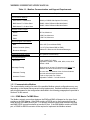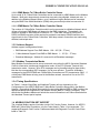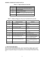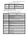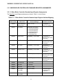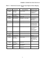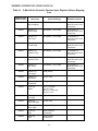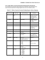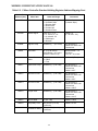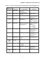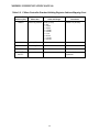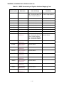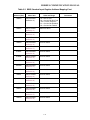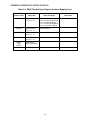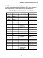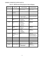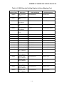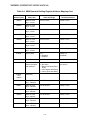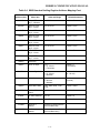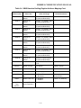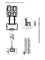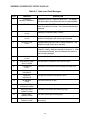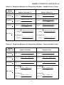
1
Instruction No. GF-114 AERCO INTERNATIONAL, Inc., Northvale, New Jersey, 07647 USA MODBUS ® Communication Manual For C-More Boiler Controllers and Boiler Management Systems ® Modbus is a registered trademark of AEG Modicon Printed in U.S.A REVISED 11/17/06 MODBUS COMMUNICATION MANUAL TABLE OF CONTENTS PAGE PARA. SECTION 1 – INTRODUCTION & GENERAL DESCRIPTION 1-1 1.1 INTRODUCTION 1-1 1.2 AERCO BMS AND C-MORE CONTROLLER MODELS COVERED 1-1 1.3 MINIMUM MODBUS SUPPORT REQUIREMENTS 1-1 1.3.1 Communication Medium 1-2 1.3.2 Address Support 1-3 1.3.3 Modbus Transmission Modes 1-3 1.3.4 Timing Specifications 1-3 1.4 MODBUS FUNCTION SET SUPPORT 1-3 1.5 EXCEPTION RESPONSES 1-4 1.6 PHRASES, ABBREVIATIONS & ACRONYMS 1-5 SECTION 2 – STANDARD REGISTER ASSIGNMENTS 2.1 2-1 INTRODUCTION 2-1 2.1.1 Input Registers 2-1 2.1.2 Holding Registers 2-1 C-MORE BOILER CONTROLLER STANDARD REGISTER ASSIGNMENTS 2-2 2.2.1 C-More Boiler Controller Standard Input Register Assignments 2-2 2.2.2 C-More Boiler Controller Standard Holding Register Assignments 2-5 BMS CONTROLLER STANDARD REGISTER ASSIGNMENTS 2-9 2.3.1 BMS Controller Standard Input Register Assignments 2-9 2.3.2 BMS Controller Standard Holding Register Assignments 2-13 2.2 2.3 SECTION 3 – STANDARD APPLICATION OPERATIONS 3-1 3.1 INTRODUCTION 3-1 3.2 C-MORE CONTROLLER STANDARD APPLICATION OPERATIONS 3-1 3.2.1 Password Protection for Input and Holding Register Access 3-1 3.2.2 Simultaneous RS232 &RS485 Access to C-More Controller Variables 3-2 3.2.3 Direct Drive Control 3-2 3.2.4 Remote Setpoint Control 3-2 3.2.5 Combination Control 3-2 3.2.6 Broadcast Commands 3-3 3.2.7 Physical Slave Address 3-3 i MODBUS COMMUNICATION MANUAL TABLE OF CONTENTS - Continued PAGE PARA. 3.3 BMS STANDARD APPLICATION OPERATIONS 3-3 3.3.1 Password Protection For BMS Input and Holding Register Access 3-3 3.3.2 Remote Setpoint Control of BMS Slave By EMS Master 3-3 3.3.3 BMS Master Control of C-More Slaves Via Network 3-4 3.3.4 BMS Combination Mode Boiler Controller of C-More Slaves 3-4 SECTION 4 – MODBUS NETWORK SETUP & INSTALLATION 4-1 4.1 INTRODUCTION 4-1 4.2 PHYSICAL MODBUS NETWORK WIRING CONNECTIONS 4-1 4.2.1 BMS Slave To EMS Master Wiring Connections 4-1 4.2.2 BMS Master To C-More Boiler Controller Slaves 4-5 4.2.3 C-More Slaves To BMS or EMS Master 4-7 RS485 LOOP TERMINATING RESISTORS AND BIAS 4-7 4.3.1 BMS Terminating Resistor 4-7 4.3.2 C-More Boiler Controller Terminating Resistor and Bias 4-7 MODBUS NETWORK WIRING DIAGRAMS 4-11 4.4.1 Wiring Diagram for EMS Master Controlling BMS Slave With Legacy (PWM) Boilers 4-11 4.4.2 Wiring Diagram for BMS Master Controlling C-More Controller Slaves 4-11 4.4.3 Wiring Diagram for EMS Master Controlling C-More Controller Slaves 4-11 4.3 4.4 SECTION 5 – MODBUS SOFTWARE SETUP 5-1 5.1 INTRODUCTION 5-1 5.2 C-MORE BOILER CONTROLLER SETUP FOR MODBUS OPERATION 5-1 5.2.1 Modbus Monitoring and Configuration Control 5-1 5.2.2 Modbus Direct Drive Control and Monitoring 5-2 5.2.3 Modbus Remote Setpoint Control 5-2 BMS SETUP FOR MODBUS OPERATION AS A SLAVE TO AN EMS 5-3 5.3.1 BMS Monitoring and Configuration By An EMS Master 5-3 5.3.2 BMS Modbus Remote Setpoint Control By An EMS Master 5-4 BMS SETUP AS MASTER TO C-MORE BOILER CONTROLLERS 5-5 5.3 5.4 APPENDIX A - C-MORE BOILER CONTROLLER STATUS & FAULT MESSAGES & CONVERSION EQUATIONS ii A-1 MODBUS COMMUNICATION MANUAL SECTION 1 INTRODUCTION & GENERAL DESCRIPTION 1.1 INTRODUCTION. The information contained in this manual provides general guidelines for implementing a Modbus® communications network utilizing AERCO’s Boiler Management System (BMS) and C-More Boiler Controllers. All Modbus networks are implemented utilizing a Master-Slave technique where only one device, the Master, can initiate a communication sequence. AERCO C-More Controllers can only function as Slave devices in a Modbus network. However, the AERCO BMS can function both as a Master controlling C-More Slaves, or as a Slave controlled by an Energy Management System (EMS) or Building Automation System (BAS) developed by other manufacturers. 1.2 AERCO BMS AND C-MORE CONTROLLER MODELS COVERED To easily determine if your AERCO BMS or C-More Boiler Controller is equipped with Modbus capabilities, check the current software version as follows: For BMS: • Apply power to the BMS • The BMS will display: INITIALIZING followed by EPROM REV K • If REV K or higher is displayed, the BMS Controller can support Modbus • If the REV level is lower than K, the BMS Controller cannot support Modbus For C-More: • Apply external power to the C-More Controller • Scroll through the Setup Menu and observe the displayed Software Version • If 2.00 or higher is displayed, the C-More Controller can support Modbus • If a Software Version lower than 2.00 is displayed, the C-More Controller cannot support Modbus 1.3 MINIMUM MODBUS SUPPORT REQUIREMENTS Implementation of a Modbus communication network utilizing the AERCO C-More Controller and BMS will be limited to the minimum support requirements listed in Table 1-1 which follows. The remaining paragraphs in this Section provide more detailed descriptions for each of the items listed. 1-1 MODBUS COMMUNICATION MANUAL Table 1-1. Modbus Communication and Support Requirements Characteristic Requirement Communication Medium: • EMS Master-To-BMS Slave RS232 (or RS485 With Optional Converter) • BMS Master-To-C-More Slave RS485, 2-Wire Differential Bus With Shield • EMS Master-To- C-More Slave RS485, 2-Wire Differential Bus With Shield Allowable Cable Lengths • RS232 50 Feet, Maximum • RS485 4,000 Feet, Maximum • PWM 1,000 Feet, Maximum Address Support From Master: • BMS 128 to 247 (From a Master EMS) • C-More Controller (Slave) 1 to 127 (From Master BMS or EMS) • Broadcast Messages Address 0 is Reserved for Broadcast Messages Transmission Mode Support RTU (Remote Terminal Unit) Timing Specifications: • Baud Rate Message Framing Fixed at 9600 For C-More Adjustable For BMS: 2400, 4800, 9600, 14.4k, 19.2k Default = 9600 Silent period of at least 3.5 character times Before first character and After last character of message • Character Framing No more than 1.5 character times of silence between received and transmitted characters • Heartbeat Timeout Fixed at 10 seconds For C-More Adjustable For BMS: 5 to 240 Seconds 1.3.1 Communication Medium The communication medium for each of the possible Modbus network configurations may vary depending on the Master/Slave scenario being implemented. Detailed installation procedures and wiring diagrams for the configurations described in the following paragraphs are provided in Section 4 of this manual. 1.3.1.1 EMS Master To BMS Slave The Modbus network connections between the EMS and BMS will depend on the type of port provide on the EMS Master. If the EMS contains a RS232 port, a direct connection can be made directly to the BMS RS232 port. For optimum results the wire length between the EMS and BMS RS232 connection should not exceed 50 feet. If the EMS Master contains a RS485 port, a RS485-to-RS232 converter will be required to implement the Modbus network. 1-2 MODBUS COMMUNICATION MANUAL 1.3.1.2 BMS Master To C-More Boiler Controller Slaves Up to a total of 32 C-More Boiler Controllers can be connected to a BMS Master on the Modbus Network. Multi-point drop network connections are made using shielded, twisted-pair wire. In addition to the Modbus Network Boilers, up to 8 additional Legacy Boilers can be connected using the BMS Pulse Width Modulation (PWM) wiring connection provided on connector J2. 1.3.1.3 EMS Master To C-More Boiler Controller Slaves The number of C-More Boiler Controllers which can be connected to a Modbus Network which utilizes a third party EMS Master will depend on the EMS’s limitations. Theoretically, the maximum number of Slave devices is limited to 127. If the EMS contains a RS232 port, a RS232-to-RS485 converter will be required to provide the necessary RS485 interfaces and signal levels for the C-More Boiler Controllers. Multi-drop network connections are made using shielded, twisted-pair wire. 1.3.2 Address Support Address support is assigned as follows: • BMS Address Support From EMS Master: 128 – 247 (80 – F7 hex) • C-More Address Support From BMS or EMS Master: 1 – 127 (01 – 7F hex) • Broadcast Messages: Address 0 is reserved for all Broadcast messages 1.3.3 Modbus Transmission Modes Many Modbus Controllers can be set up to transmit using either the ASCII (American Standard Code for Information Interchange) transmission mode, or the RTU (Remote Terminal Unit) transmission mode. However, since RTU messages can be formatted using far fewer binary bits than the corresponding ASCII message, it is far more efficient. Therefore, all Modbus messages for the AERCO BMS and C-More Boiler Controllers use RTU transmission ONLY. If a third-party EMS Master is being used in the Modbus network, ensure that it is set for RTU transmission. 1.3.4 Timing Specifications As Table 1-1 shows, Baud Rate and Heartbeat Timeout will vary depending on the Configurations of the AERCO BMS and C-More Boiler Controllers being used in the Modbus Network. Ensure that the Baud Rate used by the controlling Master (BMS or EMS) matches the appropriate Baud Rate supported by the Network Slaves (BMS or C-More Controllers). Also, ensure that the Modbus Master can refresh the control information to all C-More Slaves before the Heartbeat Timeout period expires. 1.4 MODBUS FUNCTION SET SUPPORT The complete Modbus protocol includes a total of 24 Function Codes. However, for AERCO BMS and C-More Boiler Controllers, only the Codes listed in Table 1-2 are supported. The supported Diagnostic Sub-Function Codes associated with Diagnostic Function Code 08 are listed in Table 1-3. 1-3 MODBUS COMMUNICATION MANUAL Table 1-2. Required Function Code Set Function Code Function Name 03 Read Holding Register (Read Multiple Registers) 04 Read Input Registers 06 Preset (Write) Single Register 08 Diagnostics (See Table 1-3 for supported Sub-Function Codes) 17 Report Slave ID Table 1-3. Minimum Diagnostic (Function Code 08) Sub-Function Set Sub-Function Code Sub-Function Name Comments 00 Return Query Data Loop-Back 01 Restart Communications Options Resets the Slave. Cancels Listen Only Mode. 02 Return Diagnostic Register Not Used 04 Force Listen Only Mode Reset by Restart Communications Option 10 Clear Counters and Diagnostic Register Also cleared at power up. Clears only the counters 12 Return Bus Communication Error Count Slave CRC errors only. 13 Return Bus Exception Error Count Slave Exception Response count. 14 Return Slave Message Count Number of messages addressed to the slave and successfully processed. Includes broadcast messages. 15 Return Slave No Response Count Number of messages addressed to the slave for which no response was returned. 18 Return Bus Character Overrun Count Number of overrun and framing errors. 1.5 EXCEPTION RESPONSES With the exception of Broadcast Messages, queries transmitted by the Master expect a normal response from the addressed Slave on the network. However, if the addressed Slave cannot process or interpret the message, it will respond with one of the Exception Codes listed in Table 1-4. 1-4 MODBUS COMMUNICATION MANUAL Table 1-4. Minimum Exception Code Set Exception Code Description Comments 01 Illegal Function The function code received is not valid or is not supported. 02 Illegal Data Address The data address received is invalid or is not accessible due to security setting. 03 Illegal Data Value The data value received is not valid 1.6 PHRASES, ABBREVIATIONS & ACRONYMS The phrases, abbreviations and acronyms used in this manual are listed in Table 1-5. Table 1-5. Phrases, Abbreviations and Acronyms Phrase, Abbreviation or Acronym Meaning ASCII American Standard Code for Information Interchange BAS Building Automation System Baud Bits per Second (bps) BMS Boiler Management System C-More Controller (or Control Box) A control system developed by AERCO International and currently used in all Benchmark and KC Series product lines EMS Energy Management System FDX Full-Duplex HDX Half-Duplex Hex Hexadecimal Number (0 - 9, A - F) I/O Box Input/Output (I/O) Box currently used on all Benchmark and KC Series products LSB Least Significant Byte Modbus® A serial, half-duplex data transmission protocol developed by AEG Modicon MSB Most Significant Byte RS232 A standard for serial, full-duplex (FDX) transmission of data based on the RS232 Standard RS422 A standard for serial, full-duplex (FDX) transmission of data based on the RS422 Standard RS485 A standard for serial, half-duplex (HDX) transmission of data based on the RS485 Standard RTU Remote Terminal Unit 1-5 MODBUS COMMUNICATION MANUAL SECTION 2 STANDARD REGISTER ASSIGNMENTS 2.1 INTRODUCTION This Section provides the standard data register addresses assigned to the AERCO and CMore Boiler Controllers and the AERCO Boiler Management System (BMS). These data registers consist of Input Registers and Holding Registers. All register addresses provided throughout this manual are expressed as hexadecimal numbers. 2.1.1 Input Registers The Input Registers for the AERCO C-More Boiler Controllers and AERCO BMS are intended for information and functions that cannot or should not be controlled remotely. Therefore, unless otherwise specified, ALL Input Register data are READ ONLY. 2.1.2 Holding Registers The Holding Registers for the AERCO C-More Boiler Controllers and AERCO BMS are intended for information and functions that can be read or written (R/W). Therefore unless otherwise specified, all Holding Register data are R/W. CAUTION DO NOT write in any Register Addresses marked as “Reserved” in the Input Register and Holding Register Tables which follw. Failure to observe this precaution may result in unstable operation. 2-1 MODBUS COMMUNICATION MANUAL 2.2 C-MORE BOILER CONTROLLER STANDARD REGISTER ASSIGNMENTS 2.2.1 C-More Boiler Controller Standard Input Register Assignments The Read Only Input Register addresses are listed in Table 2-1 which follows: Table 2-1. C-More Boiler Controller Standard Input Register Address Mapping Modbus Data Address (Hex) Menu Item Units and Range Default/Comments 0x0000 Default Message Display Code Enum (1 to 47) 0x0001 Unit Status Enum (0, 1, 2, 3, 4, 5) 0 = Unit Status Disabled 1 = Unit Status Standby 2 = Unit Status Manual 3 = Unit Status Remote 4 = Unit Status Auto 5 = Unit Status Fault 0x0002 Outlet Temp DEGREES_1 (0 to 1000) See Appendix A, Tables A-2 and A-3 for Conversions 0x0003 Inlet Temp DEGREES_1 (0 to 1000) See Appendix A, Tables A-2 and A-3 for Conversions 0x0004 Aux Temp DEGREES_1 (0 to 1000) See Appendix A, Tables A-2 and A-3 for Conversions 0x0005 Outdoor Temp DEGREES_2 (0 to 1000) See Appendix A, Tables A-2 and A-3 for Conversions 0x0006 Exhaust Temp DEGREES_2 (0 to 1000) See Appendix A, Tables A-2 and A-3 for Conversions 0x0007 FFWD Temp DEGREES_1 (0 to 1000) See Appendix A, Tables A-2 and A-3 for Conversions 0x0008 Fire Rate Out % (0 to 100) 0x0009 O2 Level % (0 to 25) 0x000A CO Level PPM (0 to 500) 0x000B Run Cycles Low (LSB) int (0 to 65535) 0x000C Run Cycles High (MSB) Int (0 to 15) 2-2 See Appendix A, Table A-1 for listing The actual range for run cycles is from 0 to 999,999 MODBUS COMMUNICATION MANUAL Table 2-1. C-More Boiler Controller Standard Input Register Address Mapping Cont Modbus Data Address (Hex) Menu Item Units and Range Default/Comments 0x000D Run Hours Low (LSB) int (0 to 65535) The actual range for run hours is from 0 to 999,999 0x000E Run Hours High (MSB) int (0 to 15) 0x000F Flame Strength % (0 to 100) 0x0010 Active Set point DEGREES_1 (0 to 1000) 0x0011 Fire Rate In % (0 to 100) 0x0012 Manual Fire Rate % (0 to 100) Only applicable when in the Manual Mode and controlled by the front panel interface 0x0013 Comm Address Int (0 to 127) Default = 0 Comm Address 0 disables the Controller’s Modbus communications 0x0014 Software Version int (0 to 65535) 0x0015 0x0016 (Reserved) 0x0017 Fault Log Code 0x0018 Fault Log Cycle (LOW) int (0 to 65535) 0x0019 Fault Log Cycle (HIGH) Int (0 to 15) 0x001A Fault Log Date Int (1 to 65535) 1 count/day 0x001B Fault Log Time Int (0 to 1439) 1 count/min. See Appendix A, Tables A-2 and A-3 for Conversions Fault Log 2-3 The internal variable type for fault log display cycle is long and the range is 0 to 999999 MODBUS COMMUNICATION MANUAL Table 2-1. C-More Boiler Controller Standard Input Register Address Mapping Cont Modbus Data Address (Hex) Menu Item Units and Range 0x001C Sensor Log Active Setpoint DEGREES_1 (0 to 1000) See Appendix A, Tables A-2 and A-3 for Conversions 0x001D Sensor Log Outlet Temp DEGREES_1 (0 to 1000) See Appendix A, Tables A-2 and A-3 for Conversions 0x001E Sensor Log Inlet Temp DEGREES_1 (0 to 1000) See Appendix A, Tables A-2 and A-3 for Conversions 0x001F Sensor Log FFWD Temp DEGREES_1 (0 to 1000) See Appendix A, Tables A-2 and A-3 for Conversions 0x0020 Sensor Log Exhaust Temp DEGREES_3 (0 to 1000) See Appendix A, Tables A-2 and A-3 for Conversions 0x0021 Sensor Log Outdoor Temp DEGREES_2 (0 to 1000) See Appendix A, Tables A-2 and A-3 for Conversions 0x0022 Sensor Log Aux Temp DEGREES_1 (0 to 1000) See Appendix A, Tables A-2 and A-3 for Conversions 0x0023 Sensor Log CO xmitter PPM_UNITS 0x0024 Sensor Log O2 xmitter % (0 to 100) 0x0025 Sensor Log Flow Meter GPM_UNITS 0x0026 Time Log Status 73 (“I”) = Ignition 74 (“O”) = Off 80 (“P”) = Power Up 82 (“R”) = Run 0x0027 Time Log Fire Rate % (0 to 100) 0x0028 Time Log Flame Strength % (0 to 100) 0x0029 Time Log Run Length Int (0 to 65535) 0x002A Time Log Date Int (0 to 65535) 1 count/day 0x002B Time Log Time Int (0 to 1439) 1 count/min. 2-4 Default/Comments MODBUS COMMUNICATION MANUAL 2.2.2 C-More Boiler Controller Standard Holding Register Assignments The Read/Write Input Register address assignments are listed in Table 2-2 which follows. Unless otherwise specified, all Holding Register menu items are Read/Write (R/W) Table 2-2. C-More Controller Standard Holding Register Address Mapping Modbus Data Address (Hex) Menu Item Units and Range Comments 0x0000 Net Remote Set Point DEGREES_1 (0 to 1000) See Appendix A, Tables A-2 and A-3 for Conversions. R/W ONLY in Remote Set Point Mode 0x0001 Net Direct Drive % (0 to 100) Normally Read Only. R/W ONLY in Direct Drive Mode. 0x0002 Modbus Password int (0 to 65535) Default = 0 0x0003 Password int (0 to 65535) Default = 0 0x0004 Internal Set Point DEGREES_1 (0 to 1000) See Appendix A, Tables A-2 and A-3 for Conversions Default = 130°F 0x0005 (Reserved) 0x0006 Time Int (0 to 1439) 1count/min 0x0007 Date int (0 to 65535) 1count/day Date count starts with Jan. 1, 2000. For Example: Jan. 1 2001 would equal 365 counts 0x0008 Unit of Temp bool (0, 1) 0= Degrees Fahrenheit (°F) 1=Degrees Celsius (°C) Default = °F 0x0009 Baud Rate enum (0, 1, 2, 3, 4) 0 = 2.4k 1 = 4.8k 2 = 9.6k 3 = 19.2k For C-More RS232 port ONLY bool (0, 1) 0 = Boiler 1 = Water Heater Default = Boiler enum (0, 1, 2, 3, 4, 5) 0 = 0.5 MBTU 1 = 1 MBTU 2 = 1.5 MBTU 3 = 2 MBTU 4 = 2.5 MBTU 5 = 3 MBTU Default = 1 (1 MBTU) 0x000A Unit Type 0x000B Unit Size 2-5 Default = 2 (9.6k) MODBUS COMMUNICATION MANUAL Table 2-2. C-More Controller Standard Holding Register Address Mapping-Cont. Modbus Data Address (Hex) Menu Item Units and Range Comments 0x000C Boiler Mode enum (0, 1, 2, 3, 4): 0 = Constant Setpt 1 = Remote Setpt 2 = Direct Drive 3 = Combo Unit 4 = Outdoor Reset Default = 0 (Constant Setpt) 0x000D Remote Signal enum (0, 1, 2, 3): 0 = 4 - 20 mA /1 - 5V 1 = 0 -20mA/0 - 5V 2 = PWM Input 3 = Network Default = 0 (4 - 20 mA/1 - 5V) 0x000E Bldg Ref Temp DEGREES_1 (0 to 1000) See Appendix A, Tables A-2 and A-3 for Conversions 0x000F Reset Ratio Int (1 to 99 counts) Actual Range = 0.1 to 9.9 (Counts = Actual x 10) Actual Default = 1.2 Therefore: 1.2 x 10 = 12 counts 0x0010 Outdoor Sensor Enable bool (0,1) 0 = False 1 = True Default = 0 (False) 0x0011 System Start Temp DEGREES_2 (0 to 1000) See Appendix A, Tables A-2 and A-3 for Conversions Default = 60°F 0x0012 Set Point Lo Limit DEGREES_1 (0 to 1000) See Appendix A, Tables A-2 and A-3 for Conversions Default = 60°F 0x0013 Set Point Hi Limit DEGREES_1 (0 to 1000) See Appendix A, Tables A-2 and A-3 for Conversions Default = 200°F 0x0014 Temp Hi Limit DEGREES_1 (0 to 1000) See Appendix A, Tables A-2 and A-3 for Conversions Default = 210°F 0x0015 Max Fire Rate % (40 - 100) Default = 100% 0x0016 Pump Delay Timer MIN_UNITS (0 to 30) 1count/min Default = 0 min. 0x0017 Aux Start On Delay SEC_UNITS (0 to 120) 1count/sec Default = 0 sec. 2-6 MODBUS COMMUNICATION MANUAL Table 2-2. C-More Controller Standard Holding Register Address Mapping-Cont. Modbus Data Address (Hex) Menu Item Units and Range Comments 0x0018 Failsafe Mode enum (0, 1) 0=Shutdown 1=Constant Setpoint Default = 0 (Shutdown) 0x0019 Low Fire Timer SEC_UNITS (2 to 60) 1count/sec Default = 2 sec. 0x001A Prop Band ABS_DEG_1 (0 to 1000) See Appendix A, Tables A-2 and A-3 for Conversions 0x001B Integral Gain 0.00 to 2.00 (0.01 increments) Actual x 100 Counts Defaults: Boiler: 0.10 (10 counts), Heater:1.60 (160 counts) 0x001C Derivative Time MIN_UNITS (0.00 to 2.00) (0.01 min. increments) 1count/0.01min Actual x 100 Counts Defaults: Boiler: 0.00 min. (0 counts) Heater: 0.10 min (10 counts) 0x001D Min Load Adjust ABS_DEG_1 (0 to 1000) Water Heater ONLY See Appendix A, Tables A-2 and A-3 for Conversions 0x001E Max Load Adjust ABS_DEG_1 (0 to 1000) Water Heater ONLY See Appendix A, Tables A-2 and A-3 for Conversions 0x001F Outlet Feedback bool (0, 1) 0 = Off 1 = On Default = 1 (On) Water Heater ONLY 0x0020 Thru 0x003B (Reserved) 0x003C Set Point Limiting bool (0, 1) 0 = Disabled 1 = Enabled Default = 0 (Disabled) 0x003D Set Point Limit Band ABS_DEG_1 (0 to 1000) 0x003E Thru 0x0042 (Reserved) 2-7 See Appendix A, Tables A-2 and A-3 for Conversions MODBUS COMMUNICATION MANUAL Table 2-2. C-More Controller Standard Holding Register Address Mapping-Cont. Modbus Data Address (Hex) Menu Item 0x0043 Sensor Log Interval Enum (0 to 8) 0 = Off 1 = 1 Min. 2 = 5 Min. 3 = 15 Min. 4 = 30 Min. 5 = 1 Hr. 6 = 6 Hrs 7 = 12 Hrs. 8 = 24 Hrs. 0x0044 Fault Log Pointer int 0 - 9 0x0045 Sensor Log Pointer int 0 - 1199 0x0046 Time Log Pointer int 0 - 10239 0x0047 Thru 0xFFFF Units and Range (Reserved) Comments Default = 4 (30 min) Available for future expansion. 2-8 MODBUS COMMUNICATION MANUAL 2.3 BMS CONTROLLER STANDARD REGISTER ASSIGNMENTS 2.3.1 BMS Controller Standard Input Register Assignments The Read Only Input Register address assignments for the BMS are listed in Table 2-3 which follows on the next page. Table 2-3. BMS Standard Input Register Address Mapping Modbus Data Address (Hex) Menu Item Units and Range 0x0000 (Reserved) 0x0001 Header Temperature 40 to 220°F 0x0002 Outside Air Temperature -60 to 120°F 0x0003 Indoor Air Temperature 40 to 160°F 0x0004 Fire Rate Out 0 to 100% (out to boilers) 0x0005 Header Set Temperature 40 to 220°F 0x0006 Network Address 0, 128 to 247 0x0007 Total Boilers Fired 0 to 40 0x0008 Total Boilers On Line 0 to 40 0x0009 (Reserved) 0x000A Fault/Message Code 0x000B thru 0x000F (Reserved) 0x0010 Lead Boiler Number 1 to 40 0 to 65535 Bit: 0 = Outside Air Sensor 1 = Header Sensor Error 2 = Interlock 1 Error 3 = Interlock 2 Error 4 = Indoor Air Sensor Error 5 = 4-20mA Input Error 2-9 Default/Comments Default = 0 (If Address = 0, BMS is Off-Line as a Slave) MODBUS COMMUNICATION MANUAL Table 2-3. BMS Standard Input Register Address Mapping-Cont. Modbus Data Address (Hex) Menu Item Units and Range Comments 0x0011 Boiler 1 Status 119 = Not On-Line 120 = On-Line But Not Fired 1–40 = Fired & Sequence Boilers 1 - 8 are referred to as the Legacy Boilers. 0x0012 Boiler 2 Status (Same As Above) (Same As Above) 0x0013 Boiler 3 Status (Same As Above) (Same As Above) 0x0014 Boiler 4 Status (Same As Above) (Same As Above) 0x0015 Boiler 5 Status (Same As Above) (Same As Above) 0x0016 Boiler 6 Status (Same As Above) (Same As Above) 0x0017 Boiler 7 Status (Same As Above) (Same As Above) 0x0018 Boiler 8 Status (Same As Above) (Same As Above) 0x0019 Boiler 9 Status (Net Boiler 1) 119 = Not On-Line 120 = On-Line But Not Fired 1–40 = Fired & Sequence 121 = On-Line But Disabled 122 = On-Line But Faulted Boilers 9 - 32 are the Network Boilers 0x001A Boiler 10 Status (Net Boiler 2) Same As Above 0x001B Boiler 11 Status (Net Boiler 3) Same As Above 0x001C Boiler 12 Status (Net Boiler 4) Same As Above 0x001D Boiler 13 Status (Net Boiler 5) Same As Above 0x001E Boiler 14 Status (Net Boiler 6) Same As Above 0x001F Boiler 15 Status (Net Boiler 7) Same As Above 0x0020 Boiler 16 Status (Net Boiler 8) Same As Above 0x0021 Boiler 17 Status (Net Boiler 9) Same As Above 0x0022 Boiler 18 Status (Net Boiler 10) Same As Above 0x0023 Boiler 19 Status (Net Boiler 11) Same As Above 2-10 MODBUS COMMUNICATION MANUAL Table 2-3. BMS Standard Input Register Address Mapping-Cont. Modbus Data Address (Hex) Menu Item Units and Range 0x0024 Boiler 20 Status (Net Boiler 12) 119 = Not On-Line 120 = On-Line But Not Fired 1–40 = Fired & Sequence 121 = On-Line But Disabled 122 = On-Line But Faulted 0x0025 Boiler 21 Status (Net Boiler 13) Same As Above 0x0026 Boiler 22 Status (Net Boiler 14) Same As Above 0x0027 Boiler 23 Status (Net Boiler 15) Same As Above 0x0028 Boiler 24 Status (Net Boiler 16) Same As Above 0x0029 Boiler 25 Status (Net Boiler 17) Same As Above 0x002A Boiler 26 Status (Net Boiler 18) Same As Above 0x002B Boiler 27 Status (Net Boiler 19) Same As Above 0x002C Boiler 28 Status (Net Boiler 20) Same As Above 0x002D Boiler 29 Status (Net Boiler 21) Same As Above 0x002E Boiler 30 Status (Net Boiler 22) Same As Above 0x002F Boiler 31 Status (Net Boiler 23) Same As Above 0x0030 Boiler 32 Status (Net Boiler 24) Same As Above 0x0031 Boiler 33 Status (Net Boiler 25) Same As Above 0x0032 Boiler 34 Status (Net Boiler 26) Same As Above 0x0033 Boiler 35 Status (Net Boiler 27) Same As Above 0x0034 Boiler 36 Status (Net Boiler 28) Same As Above 2-11 Comments MODBUS COMMUNICATION MANUAL Table 2-3. BMS Standard Input Register Address Mapping-Cont. Modbus Data Address (Hex) Menu Item Units and Range 0x0035 Boiler 37 Status (Net Boiler 29) 119 = Not On-Line 120 = On-Line But Not Fired 1–40 = Fired & Sequence 121 = On-Line But Disabled 122 = On-Line But Faulted 0x0036 Boiler 38 Status (Net Boiler 30) Same As Above 0x0037 Boiler 39 Status (Net Boiler 31) Same As Above 0x0038 Boiler 40 Status (Net Boiler 32) Same As Above 0x0039 thru 0xFFFF (Reserved For Future Expansion) 2-12 Comments MODBUS COMMUNICATION MANUAL 2.3.2 BMS Controller Standard Holding Register Assignments The Holding Register address assignments for the BMS are listed in Table 2-3 which follows. Unless otherwise specified, all Holding Register Menu items are Read/Write (R/W). Table 2-4. BMS Standard Holding Register Address Mapping Modbus Data Address (Hex) Menu Item Units and Range Default/Comments 0x0000 (Reserved) 0x0001 (Reserved) 0x0002 (Reserved) 0x0003 (Reserved) 0x0004 Net Header Set Temp 40 to 220°F Valid when Remote Signal = Network 0x0005 System Start Temp 32 to 120°F Default = 70°F 0x0006 System Start Mode 0 or 1 0 = Temp Only, 1 = Temp and Load Default = 0 0x0007 Manual Hdr Set Temp 40 to 220°F Default = 160°F 0x0008 Reference Temp 40 to 220°F Default = 70°F 0x0009 Indoor Prop Band 0.0 to 20.0°F/°F (0.5°F/°F increments) Default = 00.0°F/°F (Value x 10) 0x000A Indoor Setpoint Temp 50 to 150°F Default = 70°F 0x000B Reset Ratio 0.3 to 3.0 (0.1 increments), Default = 1.2 (Value x 10) 0x000C Max Header Temp 40 to 220°F Default = 220°F 0x000D Min Header Temp 40 to 220°F Default = 40°F 0x000E Start Percent 25 to 100% Default = 45% 0x000F Stop Percent 10 to 45% Default = 18% 0x0010 Integral Gain 0.00 to 9.99 Rep/Min (in 0.01 increments Default = 0.15 Rep/Min (Value x 100) 0x0011 Header Set Mode 0, 1, or 2 0 = Constant Setpt 1 = In/Outdoor Reset 2 = Remote Setpt Default = 1 (In/Outdoor Reset) 2-13 MODBUS COMMUNICATION MANUAL Table 2-4. BMS Standard Holding Register Address Mapping Modbus Data Address (Hex) Menu Item Units and Range Default/Comments 0x0012 Derivative Gain -2.00 to 2.00 (0.00 increments) Default = 0.1 (Value x 100) 0x0013 Header Temp Bandwidth 5 to 100°F Default = 70°F 0x0014 Aux Relay Open 0 to 99% Default = 45% 0x0015 Aux Relay Mode 0 or 1 0 = 100% Fire Rate 1 = 100% Fire Rate and Off Default = 1 (100% Fire Rate & Off) 0x0016 Temp Sensor Fail Mode 0 or 1 0 = Shutdown 1 = Switch Inputs Default = 0 (Shutdown) 0x0017 Fault Alarm Relay Mode 0, 1, 2, 3 0 = All Faults, 1 = No Interlock 2 = Interlock 1 3 = Interlock 2 Default = 0 (All Faults) 0x0018 Fault Alarm Clear Method 0 or 1 0 = Automatic 1 = Manual Default = 0 (Automatic) 0x0019 Boiler Operation Mode 0, 1 or 2 0 = Parallel 1 = Sequential 2 = Combination Default = 1 (Sequential) 0x001A Number Of Combination Mode Boilers 0 to 4 Default = 0 (Start at Boiler 8 and work back to Boiler 5 to assign Combo Boilers) 0x001B (Reserved) 0x001C (Reserved) 0x001D (Reserved) 0x001E Max Power Input 50 to 100% Default = 100% (Fire Rate) 0x001F Interlock 1 Method 0 or 1 0 = Always Enabled 1 = Start Enabled Default = 1 (Start Enabled) 2-14 MODBUS COMMUNICATION MANUAL Table 2-4. BMS Standard Holding Register Address Mapping-Cont. Modbus Data Address (Hex) Menu Item Units and Range Default/Comments 0x0020 Real Time Clock Minutes 00 to 59 Minutes Present Time 0x0021 Real Time Clock Hours 00 to 23 Hours Present Time 0x0022 Real Time Clock Day of Week 1 to 7 Present Day 0x0023 Real Time Clock Year 00 to 99 Present Year 0x0024 Real Time Clock Day of Month 01 to 31 Present Day of Month 0x0025 Real Time Clock Month 01 to 12 Present Month 0x0026 Offset Temp Day 1 -50 to 50°F Default = 0°F 0x0027 Offset Temp Day 2 -50 to 50°F Default = 0°F 0x0028 Offset Temp Day 3 -50 to 50°F Default = 0°F 0x0029 Offset Temp Day 4 -50 to 50°F Default = 0°F 0x002A Offset Temp Day 5 -50 to 50°F Default = 0°F 0x002B Offset Temp Day 6 -50 to 50°F Default = 0°F 0x002C Offset Temp Day 7 -50 to 50°F Default = 0°F 0x002D Offset On Time Day 1 – Minutes 00 to 59 Minutes Default = Zero 0x002E Offset On Time Day 2 – Minutes 00 to 59 Minutes Default = Zero 0x002F Offset On Time Day 3 – Minutes 00 to 59 Minutes Default = Zero 0x0030 Offset On Time Day 4 – Minutes 00 to 59 Minutes Default = Zero 0x0031 Offset On Time Day 5 – Minutes 00 to 59 Minutes Default = Zero 0x0032 Offset On Time Day 6 – Minutes 00 to 59 Minutes Default = Zero 0x0033 Offset On Time Day 7 – Minutes 00 to 59 Minutes Default = Zero 2-15 MODBUS COMMUNICATION MANUAL Table 2-4. BMS Standard Holding Register Address Mapping-Cont. Modbus Data Address (Hex) Menu Item Units and Range Default/Comments 0x0034 Offset On Time Day 1 – Hours 00 to 23 Hours Default = Zero 0x0035 Offset On Time Day 2 – Hours 00 to 23 Hours Default = Zero 0x0036 Offset On Time Day 3 – Hours 00 to 23 Hours Default = Zero 0x0037 Offset On Time Day 4 – Hours 00 to 23 Hours Default = Zero 0x0038 Offset On Time Day 5 – Hours 00 to 23 Hours Default = Zero 0x0039 Offset On Time Day 6 – Hours 00 to 23 Hours Default = Zero 0x003A Offset On Time Day 7 – Hours 00 to 23 Hours Default = Zero 0x003B Offset Enable 0 or 1 0 = Disabled 1 = Enabled Default = 0 (Disabled) 0x003C Header Offset 0 to 5°F Default = 0°F 0x003D System Start Relay Contact Operation With Interlocks 0, 1, 2 or 3 0 = No Action 1 = Either Intlk Opens Start Relay 2 = Intlk1 Opens Start Relay 3 = Intlk 2 Open Start Relay Default = 0 (No Action) 0x003E Thru 0x0045 (Reserved) 0x0046 Offset Off Time Day 1 – Minutes 0 to 59 Minutes Default = Zero 0x0047 Offset Off Time Day 2 – Minutes 0 to 59 Minutes Default = Zero 0x0048 Offset Off Time Day 3– Minutes 0 to 59 Minutes Default = Zero 0x0049 Offset Off Time Day 4– Minutes 0 to 59 Minutes Default = Zero 0x004A Offset Off Time Day 5 – Minutes 0 to 59 Minutes Default = Zero 0x004B Offset Off Time Day 6 – Minutes 0 to 59 Minutes Default = Zero 2-16 MODBUS COMMUNICATION MANUAL Table 2-4. BMS Standard Holding Register Address Mapping-Cont. Modbus Data Address (Hex) Menu Item Units and Range Default/Comments 0x004C Offset Off Time Day 7 – Minutes 0 to 59 Minutes Default = Zero 0x004D Offset Off Time Day 1 – Hours 0 to 23 Hours Default = Zero 0x004E Offset Off Time Day 2 – Hours 0 to 23 Hours Default = Zero 0x004F Offset Off Time Day 3 – Hours 0 to 23 Hours Default = Zero 0x0050 Offset Off Time Day 4 – Hours 0 to 23 Hours Default = Zero 0x0051 Offset Off Time Day 5 – Hours 0 to 23 Hours Default = Zero 0x0052 Offset Off Time Day 6 – Hours 0 to 23 Hours Default = Zero 0x0053 Offset Off Time Day 7 – Hours 0 to 23 Hours Default = Zero 0x0054 (Reserved) 0x0055 Indoor Air Input 0 or 1 0 = 4 - 20 mA 1 = Thermistor Default = 1 (Thermistor) 0x0056 Remote Signal 0 or 1 0 = 4 - 20 mA 1 = Network Default = 0 (4 - 20 mA) 0x0057 RS232 Mode 0 or 1 0 = Normal 1 = Modbus Default = 0 (Normal) 0x0058 RS232 Baud Rate 2400, 4800, 9600, 14.4k, 19.2k Default = 9600 0x0059 Number Of Network Boilers 0 to 32 Default = 0 0x005A Min Slave Address 0 to 127 Default = 0 **0x005B Max Slave Address 0 to 127, Default = 0 **0x005C Net Boiler 1 Address Address for Network Boiler 1 (same as Boiler #9) **0x005D Net Boiler 2 Address Address for Network Boiler 2 (same as Boiler #10) 2-17 MODBUS COMMUNICATION MANUAL Table 2-4. BMS Standard Holding Register Address Mapping-Cont. Modbus Data Address (Hex) Menu Item Units and Range **0x005E Net Boiler 3 Address Address for Network Boiler 3 (same as Boiler #11) **0x005F Net Boiler 4 Address Address for Network Boiler 4 (same as Boiler #12) **0x0060 Net Boiler 5 Address Address for Network Boiler 5 (same as Boiler #13) **0x0061 Net Boiler 6 Address Address for Network Boiler 6 (same as Boiler #14) **0x0062 Net Boiler 7 Address Address for Network Boiler 7 (same as Boiler #15) **0x0063 Net Boiler 8 Address Address for Network Boiler 8 (same as Boiler #16) **0x0064 Net Boiler 9 Address Address for Network Boiler 9 (same as Boiler #17) **0x0065 Net Boiler 10 Address Address for Network Boiler 10 (same as Boiler #18) **0x0066 Net Boiler 11address Address for Network Boiler 11 (same as Boiler #19) **0x0067 Net Boiler 12 Address Address for Network Boiler 12 (same as Boiler #20) **0x0068 Net Boiler 13 Address Address for Network Boiler 13 (same as Boiler #21) **0x0069 Net Boiler 14 Address Address for Network Boiler 14 (same as Boiler #22) **0x006A Net Boiler 15 Address Address for Network Boiler 15 (same as Boiler #23) **0x006B Net Boiler 16 Address Address for Network Boiler 16 (same as Boiler #24) **0x006C Net Boiler 17 Address Address for Network Boiler 17 (same as Boiler #25) **0x006D Net Boiler 18 Address Address for Network Boiler 18 (same as Boiler #26) **0x006E Net Boiler 19 Address Address for Network Boiler 19 (same as Boiler #27) **0x006F Net Boiler 20 Address Address for Network Boiler 20 (same as Boiler #28) **0x0070 Net Boiler 21 Address Address for Network Boiler 21 (same as Boiler #29) 2-18 Default/Comments MODBUS COMMUNICATION MANUAL Table 2-4. BMS Standard Holding Register Address Mapping-Cont. Modbus Data Address (Hex) Menu Item Units and Range Default/Comments **0x0071 Net Boiler 22 Address Address for Network Boiler 22 (same as Boiler #30) **0x0072 Net Boiler 23 Address Address for Network Boiler 23 (same as Boiler #31) **0x0073 Net Boiler 24 Address Address for Network Boiler 24 (same as Boiler #32) **0x0074 Net Boiler 25 Address Address for Network Boiler 25 (same as Boiler #33) **0x0075 Net Boiler 26 Address Address for Network Boiler 26 (same as Boiler #34) **0x0076 Net Boiler 27 Address Address for Network Boiler 27 (same as Boiler #35) **0x0077 Net Boiler 28 Address Address for Network Boiler 28 (same as Boiler #36) **0x0078 Net Boiler 29 Address Address for Network Boiler 29 (same as Boiler #37) **0x0079 Net Boiler 30 Address Address for Network Boiler 30 (same as Boiler #38) **0x007A Net Boiler 31 Address Address for Network Boiler 31 (same as Boiler #39) **0x007B Net Boiler 32 Address Address for Network Boiler 32 (same as Boiler #40) **0x007C Network Baud 2400, 4800, 9600, 14.4k, 19.2k Default = 9600 0x007D Network Timeout 5 to 240 sec Default = 60 sec. 0x007E Password Lo 0 to 255 (73) Default = 0 0x007F Password Hi 0 to 255 (79) Default = 0 0x0080 Modbus Control Type 0 = Round-Robin 1 = Broadcast Default = 0 (Round Robin) 0x0081 Modbus Pass-Thru 0 = Disabled 1 = Enabled Default = 0 (Disabled) 0x0082 Thru 0xFFFF (Reserved For Future Expansion) Undefined 2-19 MODBUS COMMUNICATION MANUAL SECTION 3 STANDARD APPLICATION OPERATIONS 3.1 INTRODUCTION This Section describes the standard application operations for AERCO C-More Boiler Controllers and the AERCO Boiler Management System (BMS) and how they are achieved utilizing Modbus. Paragraphs 3.2 through 3.2.7 provide information for the C-More Boiler Controllers which can only function as Slaves in a Modbus Network. Paragraphs 3.3 through 3.3.4 provide similar information for the BMS which can function as either a Master or Slave in a Modbus Network. NOTE Additional information on Modbus hardware and software set up and installation are provided in Section 4 and Section 5 of this manual. 3.2 C-MORE CONTROLLER STANDARD APPLICATION OPERATIONS The information in the following paragraphs apply to C-More Boiler Controllers with the following exceptions: • C-More Boiler Controllers utilize a Fixed 10 second “Heartbeat” timer. • C-More Boiler Controllers, require temperature readings to be converted from “counts” to °F or °C. 3.2.1 Password Protection for Input and Holding Register Access Access to the C-More Input Register and Holding Register addresses are protected via security level passwords. Two separate Holding Register addresses (0x0002, 0x0003) are assigned for password entries, one for the Modbus (RS485) Network and one for the RS232 front panel user interface. If desired, separate security passwords can be entered for each interface. Each C-More Controller menu parameter is assigned a preset security level that controls access from the front panel user interface. If the current communication password of the front-end software does not match the C-More Slave addresses security level, access is denied. When this occurs, an Illegal Data Address Exception Code (02) is generated and the data is not changed. If a Modbus message is received to read multiple Input or Holding Registers (Function Codes 03 or 04) and one or more of the register addresses is not accessible, an Illegal Data Address Exception Code will also be generated and no data is supplied to the Master. It should be noted that Modbus “Write Multiple Registers” command (Function Code 16) is not supported by AERCO C-More Controller Slaves and will cause an Illegal Function Exception Code to be generated. The Holding Register data can be viewed without a password. However, the data cannot be changed without entering the appropriate password. The communications port security operation will mirror the security operation for viewing and adjusting parameters via the front panel keypad. Refer to C-More Operation Manual GF-112 for additional information on security passwords and menu access. 3-1 MODBUS COMMUNICATION MANUAL 3.2.2 Simultaneous RS232 & RS485 Access to C-More Controller Variables As previously mentioned, read and write access of the C-More Controller variables are protected from unauthorized access by an internal security level hierarchy. Passwords may be entered in the Slave’s Holding Registers using any of the following methods: • Locally via the front panel keypad and display • Remotely via the front panel RS232 port • Remotely via the Modbus (RS485) interface It is imperative that the user understands that the LAST change made to any menu variable (including passwords) will supersede any previous change, regardless of which of the above methods is used. There is no priority structure assigned to any of the above methods and since they are not interlocked, they may be performed concurrently. 3.2.3 Direct Drive Control In the Direct Drive Mode, the holding register parameter “Net Direct Drive” (address 0x0001) must be written or broadcast periodically from the BMS (or EMS Master) to all Slave Controllers on the network. The Modbus message will specify the Fire Rate (0 to 100%) for the addressed Slave(s). If the Net Direct Drive message is broadcast, all enabled network Slaves will be set to the same fire rate percentage. However, if different fire rates are required for specific Slaves, each Slave must be addressed individually. Each time a network Slave successfully receives the Net Direct Drive message, it will reset its Heartbeat Timer which has a fixed 10 second timeout. If this timeout period is exceeded, the C-More Controller Slave will default to “Fail-Safe Mode” (Shutdown or Constant Setpoint) stored in holding register address 0x0018. When this occurs, “Modbus Comm Fault” will be displayed. During operation in the Direct Drive Mode, only the Net Direct Drive variable in the Slave’s Holding Register can be remotely adjusted. If desired, manual control via the C-More Controller front panel can be invoked by pressing the AUTO/MAN switch on the front panel. 3.2.4 Remote Setpoint Control In the Remote Setpoint Mode, the holding register parameter “Net Remote Setpoint” (address 0x0000) must be written or broadcast periodically from the BMS (or EMS Master) to all Slave Controllers on the network. The Modbus message will specify the Setpoint Temperature for the addressed Slave(s). If the Net Remote Setpoint message is broadcast, all enabled network Slaves will be set to the same setpoint temperature. However, if different setpoint temperatures are required for specific Slaves, each Slave must be addressed individually. Each time a network Slave successfully receives the Net Remote Setpoint message, it will reset its “Heartbeat”. For C-More Controllers, the “Heartbeat” timeout is fixed at 10 seconds. If this timeout period is exceeded, the C-More Controller Slave will default to “Fail-Safe Mode” and display a “Modbus Comm Fault”. During operation in the Remote Setpoint Mode, only the “Net Remote Setpt” variable in the Slave’s Holding Register can be remotely adjusted. If desired, manual control via the C-More Controller front panel can be invoked by pressing the AUTO/MAN switch on the front panel. 3.2.5 Combination Control At the present time, the Combination Control Mode is not implemented via the Modbus network. 3-2 MODBUS COMMUNICATION MANUAL 3.2.6 Broadcast Commands Address 0 is reserved for Broadcast Messages sent by the Modbus Master. At the current time, only two holding register variables can be written by broadcast to the C-More Controller Slaves. These variables are Net Remote Setpoint and Net Direct Drive (addresses 0x0000, 0x0001). No password is required to write either of these variables. Broadcast write commands to all other holding registers will be ignored. Therefore, write commands to all other holding registers must be individually transmitted to a valid Network Slave address. Valid Slave device addresses must be within the range of 1 to 127. 3.2.7 Physical Slave Address Zero Normally, each Modbus Network Slave Controller will be assigned its own unique Comm. Address (Input Register Address 0x0013). Valid entries are from 1 to 127. However, if the default address of 0 is assigned, the C-More Slave, will not respond or process any Modbus Network messages. This effectively disables the Slave’s Modbus communication link. 3.3 BMS STANDARD APPLICATION OPERATIONS For an AERCO BMS Controller, the first eight Boilers are reserved for Legacy Boilers. These Legacy Boilers are wired to the J2 connector terminals and are controlled utilizing Pulse Width Modulation (PWM) signals, just as with earlier BMS Models, prior to implementation of Modbus. Therefore, Boiler No. 9 will be the first Modbus Network Boiler, Boiler No. 10 will be the second and so on. Up to 32 Network Boilers can be connected on a Modbus Network, in addition to the 8 Legacy Boilers. The BMS will operate the Network Boilers and the Legacy Boilers as one complete System. 3.3.1 Password Protection for BMS Input and Holding Register Access Access to BMS register addresses are protected by a password in virtually the same manner as the C-More Controllers. For the BMS, a communications security code holding register “Password Lo” and “Password Hi” (addresses 0x007E, 0x007F) must be written with the proper password for writing data in the BMS through the RS232 communications port. If an attempt is made to write data to a single holding register using an incorrect password, write access is denied. If this occurs, an Illegal Data Address Exception Code (02) is generated and the data is not changed. Reading data is allowed, even if the password is incorrect. If a Modbus message is received to read multiple Input or Holding Registers and one or more of the addresses is not accessible, an Illegal Data Address Exception Code will be sent to the EMS Master and no data is affected. Only the network control variable “Net Header Set Temp” (address 0x0004) can be written without a password and only if the BMS is programmed for Remote Setpoint Control by an EMS Master. 3.3.2 Remote Setpoint Control of BMS Slave By EMS Master All Modbus communication between a BMS Slave and an EMS Master is accomplished via the RS232 port on the BMS. If the EMS Master also contains a RS232 port, it can be directly connected to the BMS. However, if the EMS Master contains a RS485 port, a RS232-to-RS485 Converter is required. 3-3 MODBUS COMMUNICATION MANUAL To enable the Remote Setpoint Mode, the parameters “Remote Signal” and “RS232 Mode” must be set to “Network” and “Modbus” respectively. These parameter are stored in Standard Holding Register addresses 0x0056 and 0x0057 respectively. Also, ensure that the RS232 Baud Rate setting (address 0x0058) matches the EMS Baud Rate being used. In the Remote Setpoint Mode, the holding register parameter “Net Header Set Temp” (Holding Register address 0x0004) must be broadcast periodically from the EMS Master to the BMS Slave. A “Heartbeat” Timer with a timeout period defined by the variable “Network Timeout” (Holding Register address 0x007D), is reset each time the signal is successfully received. If the timeout period is exceeded, the BMS will default to its “Fail-Safe” mode and display a Network Comm Fault. 3.3.3 BMS Master Control of C-More Slaves Via Network In addition to the 8 “Legacy” Boilers, the BMS can also communicate with the up to 32 Network C-MORE Boiler Control Slaves via the BMS RS485 port. Parallel and Sequential control can be selected as before. See BMS Manual GF-108 for additional information. The “Number Of Network Boilers” must be entered at location 0x0059 in the Standard Holding Registers. The C-More Slave communication addresses (“Net Boiler 1 Address” To “Net Boiler 32 Address”) can either be manually entered in a pre-defined order in the BMS, or they can be detected from the network and operated in the order they are detected by the BMS. To manually enter Network Boiler communication addresses, leave the “Min Slave Address” and “Max Slave Address” set to their default values of 0. To allow the BMS to automatically detect the Network Boilers, enter the respective “Min Slave Address” and “Max Slave Address” in their proper location in the Standard Holding Registers (0x005A, 0X005B). The Max Slave Address must be no more than 31 above the Min Slave Address. The fire rate information will be transmitted periodically from the BMS to the CMORE boiler controls. A “heartbeat” timer will be reset in the slave each time the control information is successfully received from the BMS. If a timeout occurs, the slave will default to its “Fail-Safe Mode” and display “Modbus Comm Fault”. 3.3.4 BMS Combination Mode Boiler Control of C-More Slaves At the current time, only Legacy Boilers 5 through 8 can be selected as Combination Boilers. These Boilers are connected to the BLR 5 - BLR 8 PWM terminal connections (J2). None of the Network -Controlled Boilers (1 - 32) should be assigned as a Combination Boiler. An AERCO Combination Control Panel (CCP) is necessary to configure this type of setup. However, It should be noted that the assigned PWM Combination Boilers can still be monitored and configured on the Modbus Network by assigning a Comm Address between 1 and 127. Refer to BMS Manual GF-108 for additional information on installation and setup. 3-4 MODBUS COMMUNICATION MANUAL SECTION 4 MODBUS NETWORK HARDWARE SETUP & INSTALLATION 4.1 INTRODUCTION This Section provides basic information on planning and setup of a Modbus Communication Network utilizing AERCO C-More Boiler Controllers and a Boiler Management System (BMS). It also provides basic information on Modbus Network setup utilizing AERCO BMS/C-More Slaves with a Master EMS (or BAS) provided by other manufacturers. 4.2 PHYSICAL MODBUS RS485 NETWORK WIRING CONNECTIONS Modbus RS485 devices should be wired in a “Daisy-Chain” configuration similar to the example shown Figure 4-1. DO NOT wire the units in a “Star” configuration where all devices are connected to a central point (node). Figure 4-1. Typical Daisy-Chain Modbus/RS485 Network The physical wiring connections for a Modbus Network utilizing an AERCO BMS and C-More Boiler Controllers should be made using shielded twisted-pair wire, from 18 to 24 AWG. Examples of suitable wire are: Belden # 9841, #8761, #3105A, or equivalent. The actual locations of the wiring connectors necessary for Modbus Network implementation utilizing the AERCO BMS and C-More Boiler Controllers follow. Where necessary, connector pinout information is also provided. 4.2.1 BMS Slave To EMS Master Wiring Connections Wiring connections between an EMS Master and an AERCO BMS Slave can be made at either the RS232 (DB9) port on the left side of the BMS, or at the internal RS232 connector located on the terminal board behind the connection cover on the BMS. These connections are shown in Figure 4-2. The internal RS232 connections are used when interfacing with an EMS Master via a conduit connection at the bottom edge of the BMS enclosure. If the internal RS232 connections are used, it is recommended that nothing be connected to the external RS232 (DB9) port. If the EMS Master being used contains only an RS485 port (2-wire or 4-wire), an RS485-toRS232 Converter is required. A BMS option is available with a built-in RS485-to-RS232 Converter to permit a conduit connection between the EMS and BMS. If the external RS232 port on the left side of the BMS is used, a separate external converter is required. 4-1 MODBUS COMMUNICATION MANUAL Figure 4-2. BMS Left Side View 4-2 AUX FLT ALARM JP4 SYS START 14 SET 15 BACK 16 13 INT2 11 12 INT1 JP12 4-20 +9 MA -10 SHIELD 8 REF 6 TEMP 7 HDR 4 TEMP SEN 5 SHIELD 3 JP3 OUT 1 AIR SEN 2 JP11 +15 BLR 8 -16 BLR +13 7 -14 -10 BLR +11 6 -12 -8 +9 BLR 5 +7 BLR 4 +5 BLR 3 -6 +3 BLR 2 -4 JP2 BLR +1 1 -2 Simplified block diagrams showing the internal and external connection options between the BMS and EMS are shown in Figure 4-3. Connector pinouts for the external RS232 (DB9Female) and internal RS232 connector are shown in Figure 4-4. In addition, Figure 4-4 shows the pin assignments for the internal RS485 connector mounted on the BMS terminal board. This connector is used to interface the boilers to the Modbus network. MODBUS COMMUNICATION MANUAL Figure 4-3. EMS Master-To-BMS Slave Connection Diagrams (Sheet 1 of 2) 4-3 MODBUS COMMUNICATION MANUAL Figure 4-3. EMS Master-To-BMS Slave Connection Diagrams (Sheet 2 of 2) 4-4 MODBUS COMMUNICATION MANUAL Figure 4-4. BMS RS232 & RS485 Connectors 4.2.2 BMS Master To C-More Boiler Controller Slaves Wiring connections for Modbus operation between a BMS Master and C-More Boiler Controller Slaves are made between the BMS internal RS485 connector (Figure 4-1) and the I/O Box for the associated C-More Boiler Controller. The BMS internal RS485 connector pinouts are shown in Figure 4-4. The RS485 COMM connections at each Boiler’s I/O Box are shown in Figure 4-5. Identical I/O Boxes are used for both Benchmark and KC1000 Boilers. 4-5 MODBUS COMMUNICATION MANUAL KC1000 BENCHMARK OUTDOOR SENSOR IN SENSOR COMMON AUX SENSOR IN REMOTE INTL'K IN EXHAUST SWITCH IN DELAYED INTL'K IN NOT USED NOT USED NC COM NO + ANALOG IN+ B.M.S. (PWM) IN - NC COM NO RS-485 COMM. AUX RELAY 120 VAC, 5A, RES NOT USED SHIELD mA OUT FAULT RELAY 120 VAC, 5A, RES NOTE DO NOT TERMINATE THE SHIELDS OF THE RS485 LEADS TO THE GROUND (G) TERMINAL. THE SHIELDS MUST BE TERMINATED AT THE SOURCE ENDS ONLY. CONNECT THE SHIELDS OF THE INCOMING AND OUTGOING RS485 LEADS TOGETHER. + + G - NOT USED RS485 Modbus Connections (See NOTE) Figure 4-5. I/O Box RS485 COMM Terminal Connections 4-6 MODBUS COMMUNICATION MANUAL 4.2.3 C-More Slaves To BMS or EMS Master Wiring connections between a BMS Master and up to 32 Network C-More Boiler Controller Slaves are made directly between the BMS internal RS485 terminals (Figure 4-4) and the RS485 COMM terminals in each Boiler’s I/O Box (Figure 4-5). If a third-party EMS Master is used in place of the BMS, the Modbus Network connections will depend on the available communication port(s) on the EMS. Many EMS Models contain only a RS232 (DB9) port, while others contain either a 2-Wire or 4-Wire RS485 port. Some EMS models contain both a RS232 and a RS485 port. If the EMS is equipped with only a RS232 port, a RS232-to-RS485 converter will be required (such as a B&B Electronics, Model 485SD9TD). 4.3 RS485 LOOP TERMINATING RESISTORS AND BIAS A terminating resistor (120 ohms) on each end of the RS485 loop is designed to match the electrical impedance characteristic of the twisted-pair loop and prevent echoes or cross-talk from corrupting data on the line. Short or medium length Modbus/RS485 loops (less than 1000 feet) can usually operate satisfactorily without the terminating resistor. However, longer loop runs (over 1000), may require terminating resistors. Bias may be necessary on the RS485 loop to minimize noise on the circuit. Loop bias is accomplished by activating pull-up/pull-down resistors on the last C-More Boiler Controller in the chain. AERCO recommends that both terminating resistors and bias be implemented on the RS485 circuit as described in paragraphs 4.3.1 and 4.3.2 which follow. 4.3.1 BMS Terminating Resistor Each BMS is equipped with a built-in terminating resistor (120 ohms) on the RS485 port. Therefore, only one additional terminating resistor will be required at the other end of the RS485 loop. Ensure that the last C-More Boiler Controller Slave on the loop has its terminating resistor activated as described in paragraph 4.3.2. 4.3.2 C-More Boiler Controller Terminating Resistor and Bias C-More Boiler Controllers can function only as Slave devices on a Modbus Network. Since the Slaves are connected in a “Daisy-Chain” configuration, the terminating resistor must be enabled only in the last C-More Boiler Controller in the chain. In addition, bias must also be implemented only in the last C-More Boiler Controller. This is accomplished by setting a DIP switches on the Primary Micro-Controller (PMC) Board contained in the applicable C-More Boiler Controller. The last unit in the chain must be energized (even if disabled) to enable bias. To activate the DIP switches, proceed as follows: 1. Remove power from the last C-More Boiler Controller in the RS485 loop. 2. Loosen and remove the four (4) screws securing the front panel assembly to the chassis as shown in Figure 4-6. 3. Carefully separate the panel from the chassis. Use care to avoid applying undue stress to the ribbon cable connected between the back of the panel and the chassis-mounted printed circuit boards. 4-7 MODBUS COMMUNICATION MANUAL CAUTION The C-More Boiler Controller Printed Circuit Boards contain electronic components that are sensitive to electrostatic discharge (ESD). Prior to performing the following steps, put on an anti-static wrist strap and connect the clip lead to earth ground. Failure to observe this precaution may result in permanent damage to on-board ESD-sensitive components. 4. Put on an anti-static wrist strap and attach the clip lead to earth ground. 5. From the back of the Panel Assembly (Figure 4-7), locate the RS485 DIP switches on the PMC Board. 6. Refer to Figure 4-8 and set the “TERM” switch to the ON (Up) position. 7. Set the BIAS2 and BIAS1 switches to the ON (Up) position. 8. After the DIP switches have been set, reposition the Front Panel Assembly on the chassis and secure it in place with the four screws. FRONT PANEL SCREWS (4 PL) NOTE: THE C-MORE CONTROLLER MODEL SHOWN WITH A HORIZONTAL PANEL CONTROL LAYOUT IS USED ON KC1000 BOILERS. BENCHMARK BOILERS UTILIZE C-MORE CONTROLLERS WITH A VERTICAL PANEL CONTROL LAYOUT. Figure 4-6. C-More Control Panel - Front View 4-8 MODBUS COMMUNICATION MANUAL Figure 4-7. C-More Control Panel - Rear Views 4-9 MODBUS COMMUNICATION MANUAL RIBBON CABLE CONNECTOR (J1) SEE DETAIL “A” CBS1 J1 RS485 R55 R49 C40 R50 C38 R54 R8 C10 R7 C11 R52 U7 R46 C36 R81 C37 R53 U6 R4 R62 C9 U3 R9 J3 R12 B1 C64 HB U21 C5 R75 C6 C1 C2 R76 R77 C43 R65 C16 C19 C29 C31 C28 C55 R70 C23 C22 R24 R25 R26 R28 C18 C26 R27 U4 C34 C20 R18 R16 U18 C45 C33 R42 R43 R41 R40 R39 C35 C32 C27 R32 R14 R17 C63 R61 R59 C42 R60 U5 R38 R36 R35 U19 C56 R71 R73 R72 CR1 C54 R63 C41 R64 C30 R37 U16 DS3 CR2 R57 C66 R34 C25 R29 R30 R31 R33 Y2 J4 Q2 C15 R13 C14 BH1 U2 R44 R45 C7 R3 Q1 R56 C65 R80 C8R58 R2 R6 R51 C13 R10 C12 R47 R48 R11 R5 C39 S2 U8 R1 RS485 CBS2 CURR/VOLT ON = CURR OFF = VOLT S1 C17 C44 R15 U15 C24 R22 C21 R23 R21 R20 R19 U10 U17 U11 R66 U9 C51 C58 U20 C53 U1 C52 C57 C4 R74 C3 C61 Y1 C50 R69 R68 R67 C48 J2 C59 C60 DS4 DS5 C49 U13 U14 U12 C62 R78 R79 C46 C47 RS232 CBS4 CBS3 PMC BOARD RS485 SET THE BIAS2, TERM & BIAS1 DIP SWITCHES TO THE ON (UP) POSITION TO ACTIVATE EACH FUNCTION S2 Figure 4-8. C-More Control Panel PMC Board 4-10 MODBUS COMMUNICATION MANUAL 4.4 MODBUS NETWORK WIRING DIAGRAMS Sample Modbus Network wiring diagrams for the basic circuit configurations are provided in paragraphs 4.4.1 through 4.4.3. It should be noted that these diagrams are only intended as a guide and do not include all possible scenarios. If a third-party EMS is being utilized, refer to the manufacturer’s manual prior to attempting any network wiring connections. CAUTION It is imperative that polarity be maintained between all Modbus Network connections. The Network will not operate if the proper polarity is not maintained. Also, twisted-pair wiring shield should only be terminated at the controlling Master Controller for the Modbus Network. Shields must not be le 4.4.1 Wiring Diagrams for Master EMS Controlling BMS Slave With Legacy (PWM) Boilers Figure 4-9 provides a sample wiring diagram for a BMS Unit being controlled by an EMS Master equipped with a RS485 port. 4.4.2 Wiring Diagram for Master BMS Controlling Networked C-More Slaves Wiring connections for the “Network” Boilers are made at the BMS RS485 port as shown in Figure 4-10. In addition, up to 8 “Legacy” Boilers can be wired to the PWM J2P terminal strip to allow control of up to 40 Boilers by one BMS. The BMS PWM terminal connections can also be used to connect AERCO Boilers which utilize older types of control systems, such as Modular Control Boxes, or C-More Controllers equipped with software version 1.61 or lower. Refer to BMS Manual GF-108 for additional setup details for the PWM “Legacy” Boilers. 4.4.3 Wiring Diagram For EMS Master Controlling C-More Controller Slaves Figure 4-11 provides a sample wiring diagram for an EMS equipped with a RS485 port. If the EMS contains a 4-wire RS485 port, refer to Figure 4-9, Detail “A” for additional wiring details. 4-11 4-12 RS485 PORT RS232 PORT 4-WIRE RS485 J2P PWM TERMINALS ------- --- MODBUS COMMUNICATION MANUAL MODBUS COMMUNICATION MANUAL 4-13 MODBUS COMMUNICATION MANUAL 4-14 MODBUS COMMUNICATION MANUAL SECTION 5 MODBUS SOFTWARE SETUP 5.1 INTRODUCTION This Section provides the information necessary to configure the AERCO C-More Boiler Controllers and a Boiler Management System (BMS) for operation on a Modbus Network. It also provides the basic setup procedures to operate the C-More Boiler Controller and BMS in each available Modbus Mode. 5.2 C-MORE BOILER CONTROLLER SETUP FOR MODBUS OPERATION The C-More Boiler Controller can be set up for three types of Modbus operating modes. These modes are as follows: • Monitoring and Configuration Only • Modbus Direct Drive Control and Monitoring • Modbus Remote Setpoint Control and Monitoring The following paragraphs provide the procedures necessary to set up the C-More Boiler Controllers for each of the above modes of operation. These procedures assume that the required wiring connections for Modbus operation have already been accomplished as described in Section 4. NOTE The appropriate password must be entered in the Setup Menu of the C-More Boiler Controller, prior to changing any of the current settings. Refer to the appropriate Operation and Maintenance Manual (GF109 for KC1000, GF110 for Benchmark) for detailed information on menu items. 5.2.1 Monitoring and Configuration Control In order for the C-More Boiler Controller to be recognized by the Modbus Master, a valid Network Comm Address must be entered in the Setup Menu as follows: NOTE A C-More Boiler Controller can be monitored or configured on the Modbus Network regardless of its mode of control. 1. Scroll through the Setup Menu until Comm Address is displayed. 2. With Comm Address displayed, press the CHANGE key. 3. Using the ▲ or ▼ arrow key, enter the appropriate Comm Address from 1 to 127. 4. Press the ENTER key to store the Comm Address in memory. 5-1 MODBUS COMMUNICATION MANUAL Once the Comm Address has been entered, the C-More Boiler Controller can be accessed the Modbus Network Master (BMS or EMS). 5.2.2 Modbus Direct Drive Control and Monitoring Modbus Direct Drive Control of the C-More Boiler Controller is set up as follows: 1. Enter and store a valid Comm Address using the procedures in paragraph 5.2.1. 2. Scroll through the Configuration Menu and change the following menu items to the settings shown: MENU OPTION SETTING Boiler Mode Direct Drive Remote Signal Network 3. The C-More Controller is now set for Direct Drive operation via the Modbus Network. AERCO recommends that the Setpoint Limiting feature in the Configuration Menu be enabled. Also, ensure that the Failsafe Mode setting is set to the desired setting (Shutdown or Constant Setpoint) in the event that the Modbus Network signal is lost. 5.2.3 Modbus Remote Setpoint Control Modbus Remote Setpoint Control of the C-More Boiler Controller is set up as follows: 1. Enter and store a valid Comm Address using the procedures in paragraph 5.2.1. 2. Scroll through the Configuration Menu and change the following menu items to the settings shown: MENU OPTION SETTING Boiler Mode Remote Setpoint Remote Signal Network 3. The C-More Controller is now set for Remote Setpoint operation via the Modbus Network. AERCO recommends that the Setpoint Limiting feature in the Configuration Menu be enabled. Also, ensure that the Failsafe Mode setting is set to the desired setting (Shutdown or Constant Setpoint) in the event that the Modbus Network signal is lost. 5-2 MODBUS COMMUNICATION MANUAL NOTE The AERCO BMS can function as either a Slave or a Master on a Modbus Network. Paragraph 5.3 provides the programming setup procedures when the BMS is a Slave to an EMS (or BAS). Paragraph 5.4 provides the programming setup procedures when the BMS is the controlling Master for C-More Boiler Controllers. 5.3 BMS SETUP FOR OPERATION AS A SLAVE TO AN EMS MASTER The BMS can be programmed as a Slave to an EMS Master on the Modbus Network in two ways: • Monitoring and Configuration Only • Modbus Remote Setpoint Control and Monitoring The setup procedures for the above operating configurations are provided in paragraphs 5.3.1 and 5.3.2 which follow. 5.3.1 BMS Monitoring and Configuration By An EMS Master To set up the BMS to be monitored or configured on the Modbus Network, proceed as follows: 1. Press the FIELD ADJ key on the BMS front panel to enter the Field Adjust Mode. The yellow LED on the key should be lit. 2. Press the AIR TEMP key until RS232 MODE is shown on the top line of the display. If necessary, press the ▲ or ▼ arrow key until MODBUS SLAVE appears in the second line of the display. 3. Press the AIR TEMP key again until RS232 BAUDRATE is shown on the top line of the display. Press the ▲ or ▼ arrow key to select the appropriate baud rate. 4. Press the AIR TEMP key again until MODBUS ADDRESS is shown on the top line of the display. Press the ▲ or ▼ arrow key to set the desired address for the BMS on the Modbus Network. 5. Press the FIELD ADJ key to exit the Field Adjust Mode. The yellow LED on the key should go off. The BMS is now set up to be monitored or configured on the Modbus Network. Remember that the configuration can only be changed on the Modbus Network by first entering a valid password for PASSWORD LO and PASSWORD HI. 5-3 MODBUS COMMUNICATION MANUAL 5.3.2 BMS Modbus Remote Setpoint Control By An EMS Master To configure the BMS for Remote Setpoint Control from an EMS Master, proceed as follows: 1. Press the FIELD ADJ key on the BMS front panel to enter the Field Adjust Mode. The yellow LED on the key should be lit. 2. Press the AIR TEMP key until RS232 MODE is shown on the top line of the display. If necessary, press the ▲ or ▼ arrow key until MODBUS SLAVE appears in the second line of the display. 3. Press the AIR TEMP key again until RS232 BAUDRATE is shown on the top line of the display. Press the ▲ or ▼ arrow key to select the appropriate baud rate. 4. Press the AIR TEMP key again until MODBUS ADDRESS is shown on the top line of the display. Press the ▲ and ▼ arrow keys to set the required address for the BMS on the Modbus Network. 5. Press the AIR TEMP key again until NETWORK TIMEOUT is shown in the top line of the display. Press the ▲ and ▼ arrow keys to select the maximum allowable time (in seconds) for the EMS (or BAS) to refresh the Remote Setpoint information being sent to the BMS. AERCO recommends that a time be selected that is at least 3 times the normal refresh rate. This will allow for the loss of 1 or 2 transmissions without timing out. 6. Press the AIR TEMP key again until REMOTE SIGNAL is shown in the top line of the display. Press the ▲ or ▼ arrow key to select MODBUS. 7. Press the FIELD ADJ key to exit the Field Adjust Mode. The yellow LED on the key should go off. 8. To set the BMS for Remote Operation, press the CONFIG SYS key to enter the System Configuration Mode. The red LED on the key will light. 9. Press the FIELD ADJ key until HDR SET MODE is shown in the top line of the display. Press the ▲ and ▼ arrow keys to select REMOTE SET TEMP. 10. Press the CONFIG SYS key to exit the System Configuration Mode. The red LED on the key will go off. The BMS is now programmed for Remote Setpoint Operation from an EMS Master. In the event of a Modbus signal interruption, AERCO recommends that the TEMP FAIL MODE setting be set to Switch Inputs if you want the BMS to continue running the Boilers in the CONSTANT SET TEMP Mode. In this case, ensure that the REF TEMP is set to the desired setpoint temperature. 5-4 MODBUS COMMUNICATION MANUAL 5.4 BMS SETUP AS MASTER TO C-MORE BOILER CONTROLLERS To set up the BMS as a Master to Control C-More Boiler Slaves, proceed as follows: 1. Press the FIELD ADJ key on the BMS front panel to enter the Field Adjust Mode. The yellow LED on the key should be lit. 2. Press the HDR TEMP key until RS485 BAUDRATE is shown on the top line of the display. Press the ▲ and ▼ arrow keys if necessary to set the baud rate to 9600. 3. Press the HDR TEMP key again until MIN SLAVE ADDR is shown in the display. Use the ▲ and ▼ arrow keys to set the address to zero. 4. Press the HDR TEMP key again until MAX SLAVE ADDR is shown in the display. Use the ▲ and ▼ arrow keys to set the address to zero. 5. Press the HDR TEMP key until NUMBER NETW BLRS is shown on the top line of the display. Using the ▲ and ▼ arrow keys, set the number to the maximum number of C-More Boilers that will be controlled on this Modbus Network. NOTE DO NOT count the C-More Boilers or Water Heaters that will only be monitored on the Modbus Network. Only count the Boilers that will be controlled by the BMS using the Modbus connection. 6. Press the HDR TEMP key until MODBUS CNTL TYPE is shown on the top line of the display. Using the ▲ or ▼ arrow key, if necessary, set it to ROUND ROBIN. 7. Press the HDR TEMP key until NETW BOILER 1 is shown on the top line of the display. Use the ▲ and ▼ arrow keys to set the address of the first Boiler being controlled on the BMS RS485 loop. (This address must be the same as the Comm Address setting in the CMore Boiler Controller). 8. Press the HDR TEMP key again until NETW BOILER 2 is shown on the top line of the display. Use the ▲ and ▼ arrow keys to set the address of the second Boiler being controlled on the BMS RS485 loop. (This address must be the same as the Comm Address setting in the C-More Boiler Controller). 9. Repeat step 8 for each additional C-More Boiler being controlled on the BMS RS485 loop. 10. This completes programming for the BMS RS485 Network. Press the FIELD ADJ key to exit the Field Adjust Mode. The yellow LED on the key should go off. IMPORTANT Boilers #1 thru #8 are reserved for the Legacy Boilers connected to the Pulse Width Modulation (PWM) connections on the BMS. Therefore, NETW BOILER 1 is the same as Boiler #9. NETW BOILER 2 is the same as Boiler #10 and so on. 5-5 MODBUS COMMUNICATION MANUAL The BMS is now programmed to control the Networked Boilers, as well as any Legacy Boilers connected to it. The BMS will automatically detect any C-More Boiler that is programmed for Network Control as follows: • Boiler Mode = Direct Drive • Remote Signal = Network • Comm Address = Matches one of the NETW BOILER addresses stored in the BMS 5-6 MODBUS COMMUNICATION MANUAL APPENDIX A C-MORE BOILER CONTROLLER STATUS & FAULT MESSAGES AND CONVERSION EQUATIONS A-1 MODBUS COMMUNICATION MANUAL Table A-1. Status and Fault Messages Code MESSAGE DESCRIPTION 1 DISABLED HH:MM pm MM/DD/YY 2 STANDBY 3 DEMAND DELAY XX sec 4 PURGING XX sec 5 IGNITION TRIAL XX sec Displayed during ignition trial of startup sequence. The duration of cycle counts up in seconds. 6 FLAME PROVEN Displayed after flame has been detected for a period of 2 seconds. Initially, the flame strength is shown in %. After 5 seconds has elapsed, the time and date are shown in place of flame strength. 7 WARMUP XX sec 8 HIGH WATER TEMP SWITCH OPEN 9 LOW WATER LEVEL 10 LOW GAS PRESSURE The Low Gas Pressure Limit Switch is open. 11 HIGH GAS PRESSURE The High Gas Pressure Limit Switch is open. 12 INTERLOCK OPEN The Remote Interlock is open. 13 DELAYED INTERLOCK OPEN The Delayed Interlock is open. 14 AIRFLOW FAULT DURING PURGE The Blower Proof Switch opened during purge. 15 SSOV FAULT DURING PURGE The SSOV switch opened during purge. 16 PRG SWTCH OPEN DURING PURGE Displayed if ON/OFF switch is set to OFF. The display also shows the time and date that the unit was disabled. Displayed when ON/OFF switch is in the ON position, but there is no demand for heat. The time and date are also displayed. Displayed if Demand Delay is active. Displayed during the purge cycle during startup. The duration of the purge cycle counts up in seconds. Displayed for 2 minutes during the initial warm-up only. The High Water Temperature Limit Switch is open. The Water Level Control board is indicating low water level. The Purge Position Limit switch on the Air/Fuel valve opened during purge. A-2 MODBUS COMMUNICATION MANUAL Table A-1. Status and Fault Messages –Cont. Code MESSAGE DESCRIPTION 17 IGN SWTCH OPEN DURING IGNITION The Ignition Position Limit switch on the Air/Fuel valve opened during ignition. 18 AIRFLOW FAULT DURING IGN The Blower Proof Switch opened during ignition. 19 AIRFLOW FAULT DURING RUN The Blower Proof Switch opened during run. 20 SSOV FAULT DURING IGN The SSOV switch closed or failed to open during ignition. 21 SSOV FAULT DURING RUN The SSOV switch closed for more than 15 seconds during run. 22 FLAME LOSS DURING IGN The Flame signal was not seen during ignition or lost within 5 seconds after ignition. 23 FLAME LOSS DURING RUN The Flame signal was lost during run. 24 HIGH EXHAUST TEMPERATURE 25 LOSS OF POWER A power loss occurred. The time and date when power was restored is displayed. 26 LOSS OF SENSOR Not Currently Used 27 LOSS OF SIGNAL Not Currently Used 28 HIGH O2 LEVEL Not Currently Used 29 LOW O2 LEVEL Not Currently Used 30 HIGH CO LEVEL Not Currently Used 31 SSOV RELAY FAILURE 32 RESIDUAL FLAME 33 HEAT DEMAND FAILURE 34 IGN SWTCH CLOSED DURING PURGE The Ignition Position Limit switch on the Air/Fuel valve closed during purge. 35 PRG SWTCH CLOSED DURING IGNITION The Purge Position Limit switch on the Air/Fuel valve closed during ignition. 36 SSOV SWITCH OPEN 37 IGNITION BOARD COMM FAULT 38 WAIT The High Exhaust Temperature Limit Switch is closed. A failure has been detected in one of the relays that control the SSOV. The Flame signal was seen for more than 60 seconds during standby. The Heat Demand Relays on the Ignition board failed to activate when commanded. The SSOV switch opened during standby. Communication fault between the Ignition board and the CPU board. Prompts the operator to wait. A-3 MODBUS COMMUNICATION MANUAL Table A-1. Status and Fault Messages –Cont. Code MESSAGE DESCRIPTION 39 DIRECT DRIVE SIGNAL FAULT 40 REMOTE SETPT SIGNAL FAULT The remote setpoint signal is not present or is out of range. 41 OUTDOOR TEMP SENSOR FAULT The temperature measured by the Outdoor Air Sensor is out of range. 42 OUTLET TEMP SENSOR FAULT The temperature measured by the Outlet Sensor is out of range. 43 FFWD TEMP SENSOR FAULT The temperature measured by the FFWD Sensor is out of range. 44 HIGH WATER TEMPERATURE The temperature measured by the Outlet Sensor exceeded the Temp Hi Limit setting. 45 LINE VOLTAGE OUT OF PHASE The High AC voltage is out of phase from the low AC voltage. 46 STEPPER MOTOR FAILURE 47 SETPT LIMITING ACTIVE Setpoint temperature has exceeded the maximum allowable setting. 48 MODBUS COMM FAULT The RS485 (Modbus) network information is not present or is corrupted. The direct drive signal is not present or is out of range. The stepper motor failed to move the valve to the desired position. A-4 MODBUS COMMUNICATION MANUAL Table A-2. Conversion Equations for Temperature Variables – Variable Counts to Temp Register Variable Type Degrees Fahrenheit (°F) Degrees Celsius (°C) DEGREES_1 (RegVar) ∗ (230) + 500 Temp(F) = + 20 1000 (RegVar) ∗ (128) + 500 Temp(C) = −7 1000 DEGREES_2 (RegVar)∗ (220) + 500 Temp(F)= − 80 1000 (RegVar)∗ (183) + 500 Temp(C) = − 62 1000 DEGREES_3 (RegVar) ∗ (520) + 500 Temp(F) = + 40 1000 (RegVar)∗ (289) + 500 Temp(C) = −4 1000 For (RegVar>0): ABS_DEG_1 For (RegVar> 0): (RegVar) ∗ (230) + 500 Temp(F) = 1000 For (RegVar<0): (RegVar) ∗ (128) + 500 Temp(C) = 1000 For (RegVar< 0): (RegVar) ∗ (230) − 500 Temp(F) = 1000 (RegVar) ∗ (128) − 500 Temp(C) = 1000 Table A-3. Conversion Equations for Temperature Variables – Temp to Variable Counts Register Variable Type Degrees Fahrenheit Degrees Celsius DEGREES_1 (degF − 20) ∗ (1000) + 115 RegVar = 230 (degC + 7) ∗ (1000) + 64 RegVar = 128 DEGREES_2 (degF − 80) ∗ (1000) + 110 RegVar = 220 (degC + 62) ∗ (1000) + 91.5 RegVar = 183 DEGREES_3 (degF + 40) ∗ (1000) + 300 RegVar = 600 (degC − 4) ∗ (1000) + 144.5 RegVar = 289 For (degF>0): For (degC> 0): (degF) ∗ (1000) + 115 RegVar = 230 (degC) ∗ (1000) − 115 RegVar = 128 For (degF<0): For (degC<0): (degF) ∗ (1000) − 115 RegVar = 230 (degC) ∗ (1000) − 64 RegVar = 128 ABS_DEG_1 A-5