1
Total Access 1248
CLEI: VAMBDOOA _ _
Product P/N: 1179641L4
Octal T1 IMA DSLAM
Issue Date: 0905
Document P/N: 61179641L4-22A
FAN MODULE
1179675G1
1179641L4
A
T1/E1 1-8
PWR
ALM
TOP:POTS
BOTTOM: ADSL+POTS
PORTS 1-24
TOP:POTS
BOTTOM: ADSL+POTS
PORTS 25-48
5
7
6
T1/E1
8
ALARM
-48V RET -48V RET
EXPANSION
OUT
ETHERNET
B
CRAFT
USE COPPER CONDUCTORS ONLY!
-48V .....,5.0A
REQUIRED TOOLS
The following tools and materials are required to install the
Total Access 1248:
♦ Wire-wrap tool
♦ #2 phillips-head screwdriver
♦ #1 phillips-head screwdriver
♦ Straight-slot screwdriver
♦ Multimeter (ohmmeter and voltmeter)
♦ Crimping tool for ground and power lugs
♦ Wire strippers and side cutters
MOUNTING THE TOTAL ACCESS 1248
The Total Access 1248 is shipped with two sets of mounting
brackets that accommodate either a 19-inch or 23-inch rack.
♦ The mounting brackets used for a 19-inch rack are
P/N 3265540.
♦ The mounting brackets used for a 23-inch rack are
P/N 3265541.
Attach the mounting brackets to the front of a rack for both
flush or mid-mount configurations.
C
A
B
R
O
N
T
19-inch Mounting Brackets
F
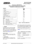
The Total Access 1248 is a mini-DSLAM that accepts up to
eight T1 network feeds assigned to a single IMA group.
Inverse Multiplexing over ATM (IMA) is a technology used to
bond multiple (DS1) links into a single data pipe.
The Total Access 1248 provides ADSL2+ service for up to 48
subscribers per unit. Plain Old Telephone Service (POTS) is
brought in from an on-board splitter and is placed on the
same pair as the ADSL2+ signal. Since ADSL2+ and POTS are
transported on the same twisted pair, the subscriber must use
a low-pass filter on the line before attempting to use analog
services. The lines are configured for service with flow-through
provisioning using a network configuration application such
as Telcordia’s Network Configuration (NCON). Permanent
Virtual Circuits (PVCs) in the ATM network to the subscriber’s
chosen Internet Service Provider (ISP) allow the subscriber
access to the internet.
The Total Access 1248 is rack-mountable and measures 1.75
inches (1U) high, 17.25 inches wide, and 11.125 inches deep
(measurements do not include the mounting brackets). The
device may be powered using one or two –48 VDC sources, one
for a non-redundant power configuration, two for a redundant
power configuration.
K
DESCRIPTION
FA
N
MO
DU
1179
675G
1
LE
Mid Mount
Flush Mount
23-inch Mounting Brackets
TOTAL ACCESS 1248 CONNECTIONS
The following sections describe the Total Access 1248 ground
connections and power connections.
Ground Connection
The ground wire can be 12 to 18 AWG,
however, it must be equal to or greater
than the wire gauge used for power.
The Total Access 1248 must be
grounded to a reliable grounding
source.
To connect the ground wire, perform
the following steps:
1. Connect the ground wire (fitted
with a loop terminal end) to the
ground lug on the front of the Total Access 1248.
2. Clean the surface of the frame ground source and
apply an appropriate antioxidant.
3. Connect the other end of the ground wire to the
grounded frame.
4. Using an ohmmeter, verify continuity between the
ground lug and a known good frame ground. The
reading should be less than 1 ohm.
Power Connection
The Total Access 1248 provides
redundant power inputs. Two
sources of –48 VDC must be
provided to use the redundant
power feature. The power wires
must be 12 to 18 AWG stranded
copper. The Total Access 1248
uses a four-point terminal block
to accept the –48 VDC and –48
VDC RET leads.
CA
-48
T
VD
-48
CA
VD
-48
RE
C
VD
B
DC
ET
BR
V
-48
NOTE
If a non-redundant power configuration is required, use the
connections marked –48 VDC A and –48 VDC A RET.
1
To connect the power source, perform the following steps:
1. With the power disconnected at the source, remove
approximately 1/4 inch of insulation from the ends of
the power wire.
NOTE
2. Tighten the screws (normally provided with each
amphenol connector attached to the cable) on the
right side of each amphenol connector, and use the
cable ties (provided) threaded through the tie-down
brackets (provided) to secure the left side of the
amphenol connectors.
ADTRAN recommends an external fuse rated at 3.0 amps.
2. Using a small flat-head screwdriver, loosen the
setscrew on the top of the terminal block.
3. Insert the bare wire into the opening on the front of
the terminal block, making sure that the wire is
inserted correctly according to the labeling on the unit
above the terminal block.
4. While holding the wire in place, tighten the setscrew
until the wire is secure.
5. Repeat steps 1 to 4 until all power leads are
connected.
6. Apply power to the Total Access 1248 and test the
voltage and polarity on the terminal block using the
tops of the setscrews as test points.
ETHERNET CONNECTION
The Total Access 1248 interfaces with networks for
management through an Ethernet port. The following Ethernet
protocols are supported:
♦ IEEE 802.3, 10/100Base-T
♦ DHCP Client Mode for Management
♦ SNMP
ALARM CONNECTIONS
The Total Access 1248 provides an alarm port with three
auxiliary alarm inputs and three alarm outputs (Major, Minor,
and Critical). Alarm inputs are activated by shorting A and B
contacts (closing an externally connected relay). The outputs
provide both normally open and normally closed pins (through
internal relay contacts) for proper operation with a variety of
alarm panels. Each alarm event generates an autonomous TL1
message that is transmitted via the in-band management
channel to a monitoring device.
A cable with a high density DB-15 male connector on one end
and a stub at the other end is available (P/N 1196DB901L1)
for wire-wrap connections to an alarm panel.
NETWORK CONNECTIONS
Network connections are accomplished via the 50-pin
amphenol connector labeled T1/E1 1-8.
NOTE
♦ This cable tie may be used to assist in routing the power
cables and the ADSL+POTS cables that originate from
the right most amphenol connector.
♦ The POTS interface may be connected to the outside
plant.
Customer Connections (ADSL+POTS )
The Total Access 1248 provides 48 ADSL+POTS ports on two
50-pin male amphenol connectors. POTS is brought in from
the CO on the POTS amphenol connectors as described in the
preceding section. The ADSL is generated locally and placed
on the same pair as the corresponding POTS signal for delivery
to the subscriber.
There is a one-to-one correlation between the pins on the
ADSL+POTS amphenol connectors and the pins on the POTS
amphenol connectors.The 25th pair is not used. To establish
the ADSL+POTS connection, perform the following steps:
1. Connect the 25-pair female amphenol connectors to the
male amphenol connectors provided, labeled ADSL+POTS.
2. Tighten the screws (normally provided with each
amphenol connector attached to the cable) on the
right side of each amphenol connector, and use the
cable ties (provided) threaded through the tie-down
brackets (provided) to secure the left side of the
amphenol connectors.
FRONT PANEL LEDS
The Total Access 1248 provides front panel LEDs to reflect the
condition of the hardware. The table below lists the LEDs and
their status.
Label
Status
Description
PWR
z Green
z Yellow
Total Access 1248 is In Service
Total Access 1248 is Out of ServiceMaintenance
Total Access 1248 Failed self-test
No power present on Total Access 1248
z Red
{ Off
ALM
z Red
{ Off
ADSL2+ and POTS Connections
The Total Access 1248 uses four 25-pair amphenol
connectors which are used as follows:
♦ Two are for connection to the POTS pairs
♦ Two are for connection to the ADSL2+ plus POTS pairs
POTS Connections
To establish a POTS connection, perform the following steps:
1. Connect the cables with the 25-pair female amphenol
connectors to the male amphenol connectors provided,
labeled POTS.
2
z Yellow
Total Access 1248 is reporting a Minor
alarm
Total Access 1248 is reporting a Major
alarm
No alarms reported on Total Access
1248
EXPANSION
IN
z Green
4 Flashing
z Yellow
Connected to an upstream box
Connected with traffic
No signal
EXPANSION
OUT
z Green
4 Flashing
z Yellow
Connected to a downstream box
Connected with traffic
No signal
61179641L4-22A
CRAFT INTERFACE
Connection to the Total Access 1248 system can be made
through the DB-9 connector, labeled CRAFT, located on the
front of the 1248/1200F Host unit. A DB-9 straight cable is
required.
FAN MODULE
1179675G1
A
B
-48V RET -48V RET
EXPANSION
N
IN
EEXPANSION
OUT
USE COPPER CONDUCTORS ONLY!
-48V
48V .....,5.0A
. 5 0A
Upgrading the firmware disrupts DSL service to the
customer.
1. Connect a VT100-capable laptop/terminal to the CRAFT
port of a Total Access 1200 Series DSLAM.
2. Set the terminal baud rate to 9600 baud, 8 data bits,
no parity, 1 stop bit, and no flow control.
CRAFT
NOTE
Craft Port
Most personal computers or laptops can run communications
software that will emulate a VT100 terminal. Windows
programs such as Terminal or HyperTerminal are two such
examples in the Windows format, but there are many other
adequate, commercially available software packages, virtually
all of which allow the PC or laptop to emulate a VT100
terminal. Certain configuration items must be set on a PC or
laptop to act as a VT100 terminal for the Total Access 1248.
1. Set the parameters of the communications software to
the following settings:
♦ 9600 baud rate
♦ 8 data bits
♦ No parity
♦ 1 stop bit
♦ No flow control
2. Set the PC for direct connect on the appropriate
communications port (as opposed to dial up
connection).
3. Plug the male end of the data cable into the Total
Access 1248. Make connection to the PC or laptop as
appropriate for the equipment.
TOTAL ACCESS 1200F CONVERSION
The 4-MB Flash Upgrade must be made at 9600 baud.
3. Press and hold the Y key on the terminal keyboard and
apply power to the Total Access 1200 Series DSLAM.
When prompted, select 38400 for a faster transfer rate
(20 minutes at 38400 compared to 60 minutes at
9600).
4. If using HyperTerminal, go off-line, select properties,
change the baud rate, then go back online. VT100
settings should be set as follows:
♦ Baud Rate: 38400
♦
♦
♦
♦
5.
6.
The order of subtended Total Access 1200 Series DSLAMS
must be preserved when connecting to the Total Access
1200F for translation to the legacy ATM mode PVCs. See
the following table.
Total Access 1200F
Expansion Port
Total Access 1200 Series Client
1
Total Access 1200 Series Host
(Client 1)
2
Client 2
3
Client 3
4
Client 4
Existing Total Access 1200 Series DSLAM installations require
a software upgrade to convert the Total Access 1200 Series
DSLAMs to function with a Total Access 1200F.
To upgrade each Total Access 1200 Series DSLAM, perform
the following steps:
61179641L4-22A
7.
8.
9.
10.
Data Bits: 8
Parity: None
Stop Bits: 1
Flow Control: None
If properly connected, a row of CCCCs should begin to
display on the screen.
Download the current file identified by network
administration using the Y-Modem protocol.
If using HyperTerminal, use the Transfer > Send File...
Browse... dialogue box and identify the file by name
and location. Select YModem, then click Send.
Several messages are displayed that report system
progress for the upgrade procedure, including the
following:
♦ Erasing Flash
♦ Erase Complete
♦ Programming Flash
♦ Programming Complete
♦ Comparing Flash to SDRAM
♦ Verify Done
♦ Please set Baud Rate to 9600 and Reboot Unit Now
Reboot the Total Access 1200 Series DSLAM when the
download is completed.
Repeat steps 1 through 7 for each Total Access 1200
Series DSLAM.
Connect the Total Access 1200F expansion cables at
the DSLAM end.
Provision, test, and turn up the equipment. Refer to
“Section 4, Provisioning Defaults” and “Section 5, User
Interface” of the Total Access 1200F Installation and
Maintenance Practice (P/N 61179660L1-5) for detailed
instructions on provisioning the equipment.
3
NOTE
Access to the Total Access 1200 Series units is now
available through the Total Access 1200F craft access or
Inband Management access ports.
MAINTENANCE
The Total Access 1248 does not require routine hardware
maintenance for normal operation. Do not attempt repairs in
the field. Repair services may be obtained by returning the
defective unit to ADTRAN. Refer to the warranty for further
information. Field support for software is provided through
upgrade facilities.
Fan Modules
Configuration Code
Input
Output
Power Code (PC)
F
C
Telecommunication Code (TC)
X
X
Installation Code (IC)
A
–
This device complies with Part 15 of the FCC rules. Operation
is subject to the following two conditions:
1. This device may not cause harmful interference.
2. This device must accept any interference received,
including interference that may cause undesired
operation.
Changes or modifications not expressly approved by ADTRAN
could void the user’s authority to operate this equipment.
Four fans are installed in the Total Access 1248 in a removable
module to maintain the hardware within proper operating
temperature tolerances. With the exception of the filter, the fan
module is not field serviceable. The fan module (P/N
1179675G1) is field replaceable and is available from
ADTRAN.
To remove a fan module, perform the following steps:
1. Loosen the screw that holds the fan module in place.
2. Remove the fan module by pulling it straight out of the
chassis.
To install a new fan module, perform the following steps:
1. Insert the new fan module by pushing it straight into
the chassis.
2. Tighten the screw that holds the fan module in place.
♦ Electrostatic Discharge (ESD) can damage electronic
Fan Filters
♦ The Total Access 1248 frame ground terminal must be
The Total Access 1248 fan module comes with a single fan
filter. The filter is designed to remove particles from the air
before it is pushed through the system.
Replacement filters are available from ADTRAN individually
(P/N 1179676G1) and in quantities of 20 (P/N 1179676G2).
The filter should be inspected at least every 90 days and
replaced as necessary.
To replace a filter, remove the fan module, remove the old filter
material and tuck the new filter in, ensuring that the edges of
the filter are behind the metal tabs provided to hold the filter.
modules. When handling modules, wear an antistatic
discharge wrist strap to prevent damage to electronic
components. Place modules in antistatic packing
material when transporting or storing. When working on
modules, always place them on an approved antistatic
mat that is electrically grounded.
♦ Per GR-1089-CORE, Section 9, the Total Access 1248 is
designed to be deployed in DC-C (common) configuration
or DC-I (isolated) installation.
♦ Per GR-1089-CORE the Total Access 1248 is designed
and intended for installation as part of a Common
Bonding Network (CBN). The Total Access 1248 is not
designed nor intended for installation as part of an
Isolated Bonding Network (IBN).
connected to a reliable earth ground.
♦ Connect to a reliably grounded –48 VDC source which is
electrically isolated from the AC source. The branch
circuit overcurrent protection shall be a fuse or circuit
breaker rated minimum –48 VDC, Maximum 3A.
NOTE
♦ The POTS and ADSL+POTS ports are classified as Type 1, 3,
and 5 as defined in Appendix B of GR-1089-CORE, Issue
4 and meet the lightning and power fault criteria with
any primary protector that meets any of the voltage
limits of GR-974-CORE or GR-1361-CORE (i.e., carbon
blocks, gas tubes, solid states, etc.). Solid-state primary
protectors are not recommended as they could affect the
signal integrity of the ADSL.
COMPLIANCE
The Total Access 1248 is NRTL listed to the applicable UL
standards. The Total Access 1248 meets or exceeds all applicable requirements of NEBS, Telcordia GR-63-CORE, issue 3,
and GR-1089-CORE, issue 4. The Total Access 1248 is
intended for deployment in EEC’s, in Pedestals, directly in the
OSP, and in locations where the NEC applies. Install the Total
Access 1248 in a restricted access location.
♦ Current limiting protectors are not required.
PRICING AND AVAILABILITY 800.827.0807
For more information, refer to the applicable Installation and Maintenance Practice
(P/N 61179641L4-5 or 61179641L6-5) available online at www.adtran.com.
Warranty: ADTRAN will replace or repair this product within the warranty period if it does not
meet its published specifications or fails while in service. Warranty information can
be found online at www.adtran.com/warranty.
©2009 ADTRAN, Inc. All Rights Reserved.
TECHNICAL SUPPORT 800.726.8663
CAUTION!
SUBJECT TO ELECTROSTATIC DAMAGE
OR DECREASE IN RELIABILITY.
HANDLING PRECAUTIONS REQUIRED.
RETURN FOR REPAIR 256.963.8722
*61179641L4-22A*