1
Section 61181113L2-5A
Issue 1, November 2003
CLEI Code: T1L7HGLA _ _
Total Access 3000 H2TU-C,
HDSL2 Transceiver Unit for the Central Office
Installation and Maintenance Practice
CONTENTS
1. General...................................................................................... 1
2. Description................................................................................ 1
3. Connections .............................................................................. 3
4. Installation ................................................................................ 4
5. HDSL2 System Testing ............................................................ 6
6. SCU Control Port Operation-HDSL2 ....................................... 7
7. Provisioning .............................................................................. 8
8. HDSL2 Deployment Guidelines............................................. 30
9. Troubleshooting Procedures ................................................... 31
10. Maintenance............................................................................ 31
11. Product Specifications ............................................................ 31
12. Warranty and Customer Service ............................................. 31
Appendix A. HDSL2 Loopbacks ........................................... A-1
Appendix B. Front Panel DSX and MUX Mode Test Access B-1
H TUC
1181113L2
DSL
DSX
ALM
ESF/ SF
(YEL) (GRN)
B8ZS/ALM
(YEL) (GRN)
LBK
6SCAN
TX
E
Q
RX
TX
M
O
N
RX
TABLES
Table 1.
Table 2.
Table 3.
Table 4.
Table 5.
Table 6.
Table 7.
Table 8.
Table A-1.
Table A-2.
ADTRAN HDSL2 Unit Compatibility....................... 1
Compliance Codes ...................................................... 3
Front Panel LEDs ....................................................... 5
Provisioning Options .................................................. 8
Auto In Service Status Indications ........................... 15
HDSL2 Loss Values ................................................. 30
Troubleshooting Guide ............................................. 31
HDSL2 Total Access 3000 H2TU-C Specifications 32
HDSL2 Loopback Control Codes.......................... A-2
In-Band Addressable Loopback Codes ................. A-3
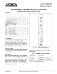
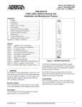
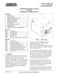
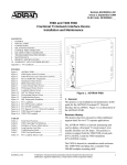
1. GENERAL
The ADTRAN Total Access® 3000 2-Wire HDSL
(HDSL2) Transceiver Unit for the Central Office
(H2TU-C) (P/N 1181113L2) is used to deploy an
HDSL2 T1 circuit using 2-wire metallic facilities. The
unit occupies one slot in a Total Access 3000 or Total
Access 3010 Shelf. Figure 1 is an illustration of the
ADTRAN Total Access 3000 H2TU-C.
Revision History
This is the initial release of this document. Future
revisions to this document will be explained in this
subsection.
2. DESCRIPTION
The DSX-1 input signal can be supplied from the
network or a Total Access 3000 Multiplexer (DS3,
STS-1, or OC-3).
61181113L2-5A
Figure 1. Total Access 3000 H2TU-C
DSX-1 signals are provided to and received from the
network, while HDSL2 signals are provided to the local
loop. The ADTRAN Total Access 3000 H2TU-C works
in conjunction with the ADTRAN H2TU-R to provide
a DS1 service up to 12,000 feet on the local loop.
Compatible ADTRAN units for this H2TU-C are shown
in Table 1.
Table 1. ADTRAN HDSL2 Unit Compatibility
Part Number
Description
122x024L2
T200 H2TU-R, Local Power
122x026L2
T200 H2TU-R, Span Power
x = any generic number
The H2TU-C can be deployed in circuits consisting of
one H2TU-C and one H2TU-R.
Trademarks: Any brand names and product names included in this document are
trademarks, registered trademarks, or trade names of their respective holders.
1
Features
The basic features of the HDSL2 Total Access 3000
H2TU-C, (P/N 1181113L2) include the following:
•
•
•
•
•
Auto In Service
Bit Error Rate Testing (BERT)
Flash Upgrade
Troubleshooting Guidance
TScan
These and other features will be discussed in the
practice.
The H2TU-C contains an onboard fuse. If the fuse
opens, it supplies a –48 VDC voltage to the fuse alarm
bus, and all front panel indicators turn off. The fuse is
not designed to be replaced in the field.
The H2TU-C uses a DC-to-DC converter to derive its
internal logic and span powering voltages from the
–48 VDC office supply. Span-powering voltages meet
all requirements of Class A2 voltages as specified by
Bellcore GR-1089-CORE.
System power and alarm bus connections are made
through the backplane of the Total Access shelf. DSX1
and HDSL2 signals are connected through the 64-pin
shelf connectors related to each individual slot.
TScan
This unit is equipped to support the TScan™ feature,
which provides data retrieval and diagnostic capabilities for remote management of DS1 circuits. TScan
allows provisioning, performance, and event history
information to be retrieved by the test center via the
Facility Data Link (FDL). In addition, TScan can be
used to determine the nature and location of faults on
DS1 trouble circuits. TScan is accessible only through
the remote test center.
NOTE
For implementation of TScan please contact
your local ADTRAN sales representative.
A patent-pending single-ended diagnostic routine
residing on a host server at the central test facility,
TScan issues commands and retrieves data via FDL
from the H2TU-C.
2
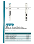
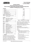
TScan performs the following functions (see Figure 2):
• Detection and location of an open, one or both
conductors
• Detection and location of a short between Tip and
Ring
• Detection and location of a ground fault from either
or both conductors
• Detection of foreign voltage
• H2TU-C Self Diagnostics
• Ability to remotely detect the presence or absence
of a ground connection in the remote mount.
TScan allows operators to integrate these capabilities
across multiple computing platforms with existing
operating systems.
CO
C
Outside Plant Facilities
X
R
Open on either conductor
R
Open on both conductors
C
R
Short between T&R
C
R
Short to ground from either
or both conductors
C
X
X
Figure 2. TScan Diagnostic Capabilities
Auto In Service
The Total Access 3000 H2TU-C supports the Auto InService feature that will automatically change the
service state of the line card from Out-of-service
Maintenance (OOS-MA) to In-Service and vice versa
based on DSL loop synchronization and/or DSX-1/DS1
alarm presence.
This and other features are discussed in more detail in
the SCU Control Port Operation-HDSL2 section.
Bit Error Rate Testing (BERT)
This Total Access HDSL2 unit has the capability to
initiate and record BERT via the Craft Access Terminal
menus. It features eight timed and user-selectable data
patterns as well as the ability to insert errors.
Compliance
Table 2 shows the compliance codes for the Total
Access 3000 H2TU-C. The Total Access 3000 H2TU-C
is NRTL listed to the applicable UL standards. The
Total Access 3000 H2TU-C is to be installed in a
restricted access location and in a Type “B” or “E”
enclosure only.
Issue 1, November 2003
61181113L2-5A
Table 2. Compliance Codes
Code
Input
Power Code (PC)
F
C
Telecommunication Code (TC)
–
X
Installation Code (IC)
A
–
This device complies with Part 15 of the FCC rules.
Operation is subject to the following two conditions:
1. This device may not cause harmful interference.
2. This device must accept any interference received,
including interference that may cause undesired
operation.
WARNING
Up to –200 VDC may be present on telecommunications wiring. The DSX-1 interface is
intended for connection to intra-building
wiring only. Ensure chassis ground is properly
connected.
P2, Row A
1
2
3
4
5
6
7
8
9
10
11
12
13
14
15
16
17
18
19
NOTE
Output
This product is intended for installation in
Restricted Access Locations only.
3. CONNECTIONS
The Total Access 3000 H2TU-C occupies one card slot
in a Total Access 3000 Shelf. Power and alarm signals
are provided to the card through the backplane of the
shelf. DSX1 and HDSL2 loop signals are connected to
the backplane on pins or mass termination shelf
connectors (amphenol) corresponding to the slot the
unit occupies. See Figure 3 for H2TU-C edge
connection wiring.
The Total Access 3000 shelf delivers DSX-1 from the
network to the H2TU-C via connectors on the
backplane labeled “Pair 7” and “Pair 8”. The HDSL2
signal is provided toward the customer via the
backplane connector labeled “Pair 2”. Pins 1 and 33 of
the connectors Pair 7 and Pair 8 are the DSX connections for the H2TU-C in Slot 1. Pins 2 and 34 of these
connectors are associated with Slot 2. Pins 3 and 35 are
associated with Slot 3, and so forth, up to pins 28 and 60
for Slot 28.
P2, Row B
- 48 volt return
Interrupt Request
MUX B Receive Data
MUX A Receive Clock
MUX A Receive Data
20
21
22
23
24
25
26
27
28
29
30
31
32
1
2
3
4
5
6
7
8
9
10
11
12
13
14
15
16
17
18
19
20
21
22
23
24
25
26
27
28
29
30
31
32
P2, Row C
Chassis ground
Chassis ground
SCU Control Lead
Fuse alarm
Interrupt Request Select
MUX B Transmit Clock
MUX A Transmit Clock
Test access bus Loop ring
Test access bus Loop tip
Receive DSX-1 Ring backup connection
Transmit DSX-1 Ring backup connection
Receive DSX-1 Ring normal connection
Transmit DSX-1 Ring normal connection
- 48 volt return
1
2
3
4
5
6
7
8
9
10
11
12
13
14
15
16
17
18
19
20
21
22
23
24
25
26
27
28
29
30
31
32
- 48 volt DC A
- 48 volt DC A
HDSL2 Loop Ring (facility)
HDSL2 Loop Tip (facility)
SCU Control Lead
SCU Control Lead
SCU Serial Interface
MUX B Transmit Data
MUX B Receive Clock
MUX A Transmit Data
Receive DSX-1 Tip backup connection
Transmit DSX-1 Tip backup connection
Receive DSX-1 Tip normal connection
Transmit DSX-1 Tip normal connection
- 48 volt DC B
- 48 volt DC B
Figure 3. H2TU-C Edge Connector Wiring
61181113L2-5A
Issue 1, November 2003
3
Powering Modes
The H2TU-C is capable of span powering the H2TU-R
by applying current to the local loop. From 10 to 150
mA of current is coupled onto the HDSL2 span to power
the H2TU-R when deployed. (See Figure 4.)
If there is a need to remove an H2TU-C from the Total
Access shelf, the H2TU-C should be provisioned for the
Out-Of-Service-Maintenance or Out-Of-ServiceUnassigned state. This will disable all HDSL2 level
alarms from being sent to the shelf. Any HDSL2 alarm
that occurred prior to changing the service will be set to
Inactive status when the H2TU-C card is removed from
the shelf.
SPAN CURRENT
TIP (+)
HDSL2
SPAN POWER
190 V
RING (-)
Figure 4. H2TU-C Span Powering Diagram
H2TU-C Alarm Outputs
Pin 32 of the H2TU-C edge connector interface
provides a fuse alarm signal that connects –48 VDC to
this pin in the presence of a blown fuse. This indicates
the card has malfunctioned and should be replaced.
4. INSTALLATION
container for returning the Total Access 3000 H2TU-C
for repair or for verification of shipping damage.
CAUTION
Electronic modules can be damaged by
Electro-Static Discharge (ESD). When
handling modules, wear an antistatic discharge
wrist strap to prevent damage to electronic
components. Place modules in antistatic
packing material when transporting or storing.
When working on modules, always place them
on an approved antistatic mat that is electrically grounded.
There are no configuration switches for the Total
Access 3000 H2TU-C. Configuration is performed via
software discussed in the SCU Control Port OperationHDSL2 section of this practice.
The Total Access 3000 H2TU-C plugs directly into the
Total Access 3000 shelf. No installation wiring is
required.
Powering Options
The H2TU-C is default enabled for span powering
mode. The H2TU-C will power the H2TU-R, but it can
be set to disable span power when the H2TU-R is being
locally powered.
CAUTION
Disabling the span power removes all voltage
from the HDSL2 loop. This will result in an
absence of sealing current which could have an
adverse effect on circuit continuity over an
extended period of time.
This product provides span powering voltage (negative
only with respect to ground, –190 VDC nominal, GFI
protection < 5 mA) and meets all requirements of
Bellcore GR-1089-CORE (Class A2) and ANSI
T1.418-2002. This product is NRTL listed to the applicable UL standards.
C A U T I O N !
SUBJECT TO ELECTROSTATIC DAMAGE
OR DECREASE IN RELIABILITY.
HANDLING PRECAUTIONS REQUIRED.
After unpacking the HDSL2 unit, inspect it for damage.
If damage has occurred, file a claim with the carrier,
then contact ADTRAN Customer Service. Refer to the
Warranty and Customer Service section for further
information. If possible, keep the original shipping
4
Issue 1, November 2003
61181113L2-5A
Instructions for Installing the Module
To install the Total Access 3000 H2TU-C, perform the
following steps:
1. If present, remove the Access Module Blank from
the appropriate access module slot of the Total
Access chassis.
2. Pull the ejector latch, located on the lower lefthand side of the Total Access 3000 H2TU-C front
panel, from its closed position.
3. Hold the unit by the front panel while supporting
the bottom edge of the module with the ejector
latch opened to engage the chassis edge.
4. Align the unit edges to fit in the lower and upper
guide grooves for the access module slot.
5. Slide the unit into the access module slot.
Simultaneous thumb pressure at the top and at the
bottom of the unit will ensure that the module is
firmly positioned against the backplane of the
chassis.
6. Secure the Total Access 3000 H2TU-C in place by
pushing in on the ejector latch.
When the unit first powers up it runs the a series of selftests. Once the power up self-test is complete, the status
LEDs will reflect the true state of the hardware.
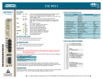
Front Panel LEDs
The Total Access 3000 H2TU-C Access Module
provides front panel LEDs to display status information.
Table 3 lists the front panel LEDs and their indications.
Table 3. Front Panel LEDs
Front Panel
Label
Status
Description
DSL
Green
Red
DSL sync, no errors currently detected, and signal margin ≥2 dB
No DSL sync, errors being detected, or signal quality < 2 dB
DSX/DS1
Green
Red
DSX-1 signal is present and synchronized and no errors are being detected
No DSX-1 signal, or signal is present with errors
ALM
Off
Red
Yellow
No alarm condition detected
Loss of DSX-1 signal to the unit
Loss of DS1 signal to the remote
ESF/SF
Off
Yellow
Green
Unit is provisioned for DS1 unframed operation
Unit is provisioned for DS1 ESF framing mode
Unit is provisioned for DS1 SF framing mode
B8ZS/
AMI
Yellow
Green
Unit is provisioned for B8ZS line code
Unit is provisioned for AMI line code
LBK
Off
Yellow
Unit is not in loopback
Unit loopback is active toward network or customer
H TUC
1181113L2
DSL
DSX
ALM
ESF/ SF
(YEL) (GRN)
B8ZS/ALM
(YEL) (GRN)
LBK
6SCAN
TX
E
Q
RX
TX
M
O
N
RX
61181113L2-5A
Issue 1, November 2003
5
5. HDSL2 SYSTEM TESTING
The ADTRAN HDSL2 system provides the ability to
monitor the status and performance of the DSX1
signals, DS1 signals, and HDSL2 loop signals. Detailed
performance monitoring is provided by the Total
Access SCU via a front panel-mounted RS-232 Control
Port. These features are valuable in troubleshooting and
isolating any system level problems that may occur at
installation or during operation of the HDSL2 system.
The following subsections describe additional testing
features.
H2TU-C Loopbacks
The H2TU-C responds to three different loopback
activation processes. First, loopbacks may be activated
using the craft interface of the Total Access 3000 SCU.
The Loopback Options screen which provides for the
H2TU-C and H2TU-R loopbacks is described in the
SCU Control Port Operation-HDSL2 section of this
practice.
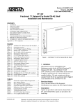
H2TU-C Bantam Jacks
The front panel of the H2TU-C includes both
monitoring and metallic splitting bantam jacks. In
general, the monitoring jacks provide a non-intrusive
tap onto a signal line that permits the connection of test
equipment to monitor the characteristics of that signal.
For example, the DSX-1 monitor jack can be used to
connect to a bit error rate tester to monitor for synchronization, test patterns, etc. The metallic splitting jacks
provide an intrusive signal interrupting access to the
line. It is very important to know the direction of the
access provided by a metallic splitting jack.
This unit contains smartloop technology. That is, the
unit will initiate the proper loopback regardless of how
the loopback control sequence is sent (framed or
unframed).
Figure 5 illustrates the complete bantam jack
arrangement and details for specific jacks.
Second, the H2TU-C responds to the industry standard
for HDSL loopbacks. A detailed description of these
loopback sequences is given in Appendix A.
The loopback condition imposed in each case is a logic
level loopback at the point within the H2TU-C where
the DSX1 signal passes into the HDSL2 modulators.
Figure 6 depicts all of the loopback locations possible
with ADTRAN HDSL2 equipment.
H2TU-C Network-Side Loopback
AIS
LOCAL
LOOP
DSX-1
H2TU-C
DS1
X
H2TU-R
H2TU-R Network-Side Loopback or
(Metallic)
H2TU-R NIU Loopback
T1
DSX-1
R1
LOCAL
LOOP
DSX-1
DSX-1
MON
RX
H2TU-C
DS1
X
H2TU-R
H2TU-R Customer-Side Loopback
X
LOCAL
LOOP
AIS
EQ
RX
HDSL2
H2TU-C
Data
Pump
H2TU-C
Power
DS1
H2TU-R
H2TU-C Customer-Side Loopback
EQ
TX
X
LOCAL
LOOP
AIS
H2TU-C
DS1
H2TU-R
H2TU-R Bidirectional Loopback
DSX-1
MON
TX
LOCAL
LOOP
DSX-1
T
H2TU-C
DSX-1
DS1
H2TU-R
R
X = Signal Inactive
D = Data Sent
Figure 5. H2TU-C Bantam Jack Arrangement
6
Issue 1, November 2003
Figure 6. HDSL2 Loopbacks
61181113L2-5A
In addition to network side loopbacks, the H2TU-C
provides customer side loopbacks initiated by using
either the terminal control port or in-band loop codes.
(See Appendix A.) In this mode, an AIS signal is transmitted to the network.
6. SCU CONTROL PORT OPERATION-HDSL2
The Total Access 3000 provides a front panel-mounted
DB-9 connector that supplies an RS-232 interface for
connection to a controlling terminal. The pinout of the
DB-9 is illustrated in Figure 7.
The H2TU-C supports two types of terminal emulation
modes.
The Manual Update Mode is a dumb terminal mode,
where the user can use print screen and log files
commands easily. This mode also includes a “3
SPACES TO UPDATE” message on the top of the
terminal screen. (Press the space bar three times to
update the screen.)
The Real Time Update Mode is a VT100 terminal mode
and is the default update mode. This mode enables all
screen highlighting and cursor placement. Print screen
and log file commands are not available in this mode.
1
6
7
8
9
2
TXD (Transmit Data)
3
RXD (Receive Data)
NOTE
If you are using a personal computer (PC) with
terminal emulation capability, be sure to
disable any power saving programs.
Otherwise, communication between the PC
and the HDSL2 unit may be disrupted,
resulting in misplaced characters or screen
time outs.
4
5
SGN (Signal Ground)
Figure 7. RS-232 (DB-9) Pin Assignments
The terminal interface operates at a data rate of 9.6
kbps. The asynchronous data format is fixed at 8 data
bits, no parity, and 1 stop bit. The line wrap feature of
emulation programs should be disabled.
61181113L2-5A
Issue 1, November 2003
7
7. PROVISIONING
Through management access via the Total Access 3000
System Controller Unit (SCU), as detailed in the SCU
Control Port Operation-HDSL2 section, the provisioning settings can be viewed and manipulated.
Table 4 lists the available provisioning options and the
factory default settings.
Table 4. Provisioning Options
Provisioning Option
Option Settings
Default Settings
1. DSX-1 Line Build Out
0-133 ft.
133-266 ft.
266-399 ft.
399-533 ft.
533-655 ft.
0 to 133 ft.
2. DSX-1/DS1 Line Code
B8ZS, AMI
B8ZS
3. DSX-1/DS1 Framing
SF, ESF, Unframed, Auto
ESF
4. Force Frame Conversion
Disabled, Enabled
Disabled
5. Smartjack Loopback
Disabled, Enabled
Enabled
6. Loopback Time Out
None, 120 Min
120 Minutes
7. Latching Loopback Mode
T1 (Disabled), FT1 (Enabled)
T1 (Disabled)
8. DS1 Tx Level
0 dB, –7.5 dB, –15 dB
0 dB
9. Span Power
Enabled, Disabled
Enabled
10. Customer Loss Indicator
AIS, Loopback, AIS/CI
AIS/CI
11. Performance Reporting Messages
None, SPRM, NPRM, AUTO (both)
AUTO
12. Loop Attenuation Alarm Threshold
0 (Disabled), 1-99 dB
30 dB
13. SNR Margin Alarm Threshold
0 (Disabled), 1-15 dB
04 dB
14. Remote Provisioning
Disabled, Enabled
Enabled
15. Service State1
In Service, Out of ServiceUnassigned, Out of ServiceMaintenance
Out of Service-Maintenance
16. Network Source
DSX, MUX A, MUX B, Auto MUX
DSX
17. External Alarms
Enabled, Disabled
Disabled
18. Auto In Service
Disabled, Enabled
Enabled
19. Auto IS Startup Period
1 hour, 4 hours, 8 hours, 24 hours
4 hours
20. Auto IS Off Period
1 hour, 4 hours, 8 hours, 24 hours
8 hours
1
The Service State defaults to Out of Service-Maintenance. This setting allows active connections to the DSX or MUX interface; however,
no alarms will be generated. The In Service setting allows full functioning connections to DSX or MUX interfaces. Out of ServiceUnassigned allows the loops to train up but will not connect to the DSX or MUX interface.
8
Issue 1, November 2003
61181113L2-5A
The screens illustrated in Figure 8 through Figure 42
are for an HDSL2 circuit deployed with the ADTRAN
HDSL2 technology. The circuit includes an H2TU-C
and H2TU-R. Other configurations are possible (for
example, an HDSL2 repeater from another vendor’s
equipment), and their displays will vary slightly from
those shown in this section.
TID:
Accessing the HDSL2 circuit information via the Total
Access 3000 SCU control port requires the user to logon
by entering a password. See Figure 8. The default
password is “PASSWORD.” The 1181018L1 SCU also
requires a username.
After successful logon, the Total Access System screen
(Figure 9) will appear. Select Access Modules (option
4) from this menu.
Total Access System
10/28/03 08:59
Unit Number:
1
Total Access System
Account Name :
'?' - System Help Screen
Figure 8. Logon Screen
Shelf: 1
Unacknowledged Alarms: None
Total Access System
10/28/03 08:59
Total Access
1.
2.
3.
4.
5.
6.
7.
System Controller
Common A - [.....]
Common B - [.....]
Access Modules
System Alarms
Network Management
Logoff
Selection:
'?' - System Help Screen
Figure 9. Total Access Screen
61181113L2-5A
Issue 1, November 2003
9
The Access Module Menus screen (Figure 10) will
display the access modules occupying the Total Access
3000 shelf. Select the corresponding channel slot
number for the desired H2TU-C. To the right of each
access module listed, the current alarm state is
indicated.
Shelf: 1
Unacknowledged Alarms: None
First displayed is the ADTRAN HDSL2 Main Menu,
from which the various OAM&P (Operation, Administrative, Maintenance, and Provisioning) screens may be
accessed (Figure 11). To display a particular screen
from the menu, press the number key associated with
the screen title and then press the ENTER key
Total Access System
10/28/03 08:59
Access Module Menus
1
2
3
4
5
6
7
8
9
10
11
12
13
14
-
H2TU-C L2...
............
............
............
............
............
............
............
............
............
............
............
............
............
[None]
[None]
[None]
[None]
[None]
[None]
[None]
[None]
[None]
[None]
[None]
[None]
[None]
[None]
15
16
17
18
19
20
21
22
23
24
25
26
27
28
-
............
............
............
............
............
............
............
............
............
............
............
............
............
............
[None]
[None]
[None]
[None]
[None]
[None]
[None]
[None]
[None]
[None]
[None]
[None]
[None]
[None]
Enter Channel Slot Number :
Figure 10. Access Module Menus Screen
Shelf: 1 Slot: 15
Total Access System
Unacknowledged Alarms: CRITICAL MAJOR
INFO
Circuit ID:
10/28/03 08:59
HDSL2 Main Menu
1.
2.
3.
4.
5.
6.
7.
8.
9.
10.
11.
12.
HDSL2 Unit Information
Provisioning
Status
Loopbacks and Test
Performance Monitoring
Scratch Pad, Ckt ID
Alarm History
Event History
System Status/PM Report
Clear PM and Alarm Histories
Troubleshooting
Flash Upgrade
Selection:
Figure 11. HDSL2 Main Menu Screen
10
Issue 1, November 2003
61181113L2-5A
The Unit Information Screen (Figure 12) provides
detailed product information on each component in the
HDSL2 circuit. ADTRAN Technical Support contact
numbers are also available from the Unit Information
Screen.
Shelf: 1 Slot: 15
Total Access System
10/28/03 08:59
Unacknowledged Alarms: CRITICAL MAJOR
INFO
Circuit ID:
ADTRAN
901 Explorer Boulevard
Huntsville, Alabama 35806-2807
--------------------- For Information or Technical Support -------------------Support Hours ( Normal 7am - 7pm CST, Emergency 7 days x 24 hours )
Phone: 800.726.8663 / 888.873.HDSL Fax: 256.963.6217 Internet: www.adtran.com
------------------------------------------------------------------------------ADTN
P/N:
S/N:
CLEI:
Manf:
Ver:
H2TU-C
1181113L2
123456789
T1L7HGLAAA
10/01/2003
21 1 A01
ADTN
P/N:
S/N:
CLEI:
Manf:
Ver:
H2TU-R
1223026L2
123456789
T1L7MERAAA
10/01/2003
16 2 A01
Figure 12. ADTRAN Information Screen
61181113L2-5A
Issue 1, November 2003
11
The Provisioning Screen (Figure 13) displays current
provisioning settings for the HDSL2 circuit. Options
that can be changed from this screen are labeled with a
number (for example, “1” for DSX-1 Line Build Out). To
change a particular option setting, select the appropriate
number and a new menu will appear with a list of the
available settings.
Note that there is more than one screen for the Provisioning Menu. Press the N (and ENTER) to move forward
to the next screen. Figure 14 shows the remainder of the
Provisioning Menu. To return to the previous screen,
press P. To return to the Main Menu, press <ESCAPE>.
To re-deploy this unit, pressing “D” will restore the
factory default settings as shown in Table 4.
The options shown in Table 4 are available with the
1223026L2 H2TU-R. Some settings may differ when
using different H2TU-As.
Shelf: 1 Slot: 14
Total Access System
Unacknowledged Alarms:
INFO
Circuit ID:
10/28/03 08:59
Provisioning
1.
2.
3.
4.
5.
6.
7.
8.
9.
10.
11.
12.
13.
14.
15.
16.
N.
DSX-1 Line Buildout
DSX-1/DS1 Line Code
DSX-1/DS1 Framing
Forced Frame Conversion
Smartjack Loopback
Loopback Timeout
Latching Loopback Mode
DS1 TX Level
Span Power
Customer Loss Indicator
PRM Setting
Loop Atten Alarm Thres
SNR Margin Alarm Thres
Remote Provisioning
Service State
Network Source
Next Page
Selection:
=
=
=
=
=
=
=
=
=
=
=
=
=
=
=
=
0-133 Feet
B8ZS
ESF
Disabled
Enabled
120 Min
T1 (Disabled)
0 dB
Enabled
AIS / CI
AUTO
30dB
04dB
Enabled
OOS Maintenance
DSX
Figure 13. Provisioning Screen, Page 1
Shelf: 1 Slot: 14
Total Access System
Unacknowledged Alarms:
MAJOR
INFO
Circuit ID:HntsvlALMn0103
10/28/03 08:59
Provisioning
17.
18.
19.
20.
D.
P.
External Alarms
Auto In Service
Auto IS Startup Period
Auto IS Off Period
=
=
=
=
Disabled
Enabled
4 hours
8 hours
Restore Factory Defaults
Previous Page
Selection:
Figure 14. Provisioning Screen, Page 2
12
Issue 1, November 2003
61181113L2-5A
The Span Status Screen (Figure 15) provides quick
access to status information for each HDSL2 receiver in
the circuit.
The Status Screen Legend (Figure 16) provides a
description of the messages that are used on the Status
screens.
Shelf: 5 Slot: 22
Total Access System
Unacknowledged Alarms:
MAJOR
INFO
Circuit ID:
Span Status Screen
ATTEN
______ <-02dB->
______
|H2TU-C |
|H2TU-R |
------>|
|
|
|------>
|
|
|
|
NET
|
|<--------->|
|
CUST
|
|17dB
17dB|
|
<------|
| MARGIN
|
|<-----DSX-1 |______|
|______|
DS1
1.
2.
3.
10/28/03 08:59
Legend
Detailed Status
View Auto In Service Status
Selection:
Figure 15. Span Status Screen
Shelf: 1 Slot: 1
Unacknowledged Alarms: None
Total Access System
10/28/03 08:59
STATUS SCREEN LEGEND
Alarm
LOS
LOF
RAI
AIS
Loop Attenuation
______
<-----------25dB------------->
______
|H2TU-C |
|H2TU-R |
<---|
|
|
|--->
|
|
|
|
|
|
|
|
|
|<---------------------------------->|
|
|
|9dB
8dB|
|
|
| |
| |
|
--->|
| Signal Margin
| |
|<--|______| above 10e-7 BER
| |______|
for H2TU-C Receiver
|
Signal Margin
above 10e-7 BER
for H2TU-R Receiver
Indicators:
Error Indicators:
= Red Alarm
ES = Errored Second
= Loss of Frame Sync SES = Severely Errored Second
= Yellow Alarm
UAS = Unavailable Second
= Blue Alarm
Figure 16. Status Screen Legend
61181113L2-5A
Issue 1, November 2003
13
The Detailed Status selection from the Span Status
Screen menu (Figure 17) displays the T1 and HDSL2
status for each receiver point.
Shelf: 1 Slot: 1
Total Access System
Unacknowledged Alarms: None
CIRCUIT ID:
Detailed HDSL2 and T1 Status
10/28/03 08:59
HDSL2 RECEIVER DATA
H2TU-C
H2TU-R
-------MARGIN(CUR/MIN/MAX): 12/00/13
ATTEN(CUR/MAX): 27/27
ES 15MIN:
001
SES 15MIN:
000
UAS 15MIN:
026
FRAMING:
LINE CODE:
ES-P/ES-L:
SES-P/SES-L:
UAS-P/UAS-L:
ALARMS:
-------07/00/09
27/28
254
000
000
T1 RECEIVER DATA
DSX-1
DS1
------------ESF
ESF
B8ZS
B8ZS
000/000
247/255
000/000
247/256
000/000
176/159
NONE
NONE
1. Zero Registers
2. Restart Min/Max
Selection:
Figure 17. Detailed Status Screen
14
Issue 1, November 2003
61181113L2-5A
The Auto In Service Status Screen (Figure 18) provides
the status of the Auto In Service feature. Options for this
feature are as follows:
The T1 alarm indications will display if the External
Alarms option is enabled on the Provisioning Screen
(Figure 13).
This screen also indicates the startup or exit period
remaining as either 1, 4, 8, or 24 hours. This is the time
during which the unit monitors both loop synchronization (Loop Sync) and T1 alarms (if enabled) and will
only go into (or out of) service if the circuit remains
synchronized and without T1 alarms during the entire
measured period. These times are also set from the
Provisioning Screen.
A link is provided (option 1) to view the Alarm History
Screen. This screen is also available by selecting option
7 on the Main Menu.
System responses displayed in the status fields on this
screen are shown in Table 5 below.
Shelf: 1 Slot: 15
Total Access System
Unacknowledged Alarms: CRITICAL MAJOR
INFO
Circuit ID:
Auto In Service Status Screen
10/28/03 08:59
Current Auto In Service State = Out-of-Service Maintenance
Auto In Service Status
= Currently in Startup Period
Auto In Service Criteria
= DSL Loop Sync (T1 alarms ignored)
NOTE: The external alarms provisioning option determines
whether T1 alarms are an auto in service criterion.
Enabling external alarms sets T1 alarms as a criterion.
Criteria
--------------DSL Loop Sync
Status
-----LOS
---Startup Period Timer--4 hrs 0 mins
-------------------------------------------------------------------------------1. View Alarm History
Selection:
Figure 18. Auto In Service Screen
Table 5. Auto In Service Status Indications
Status Field Name
System Indications
Current Auto In Service State (Line 1)
In-Service
Out of Service-Maintenance
Auto In Service Status (line 2)
Currently in startup period
Currently in exiting period
OK, Startup Period COMPLETED
OK, Startup INCOMPLETE (forced in-service)
Auto In Service Criteria (line 3)
DSL Loop Sync (T1 alarms ignored)
DSL Loop Sync and absence of T1 alarms
Criteria (current status)
DSL Loop Sync = OK or LOS (LOS shown in Figure 18)
T1 Alarm Status = Alarm or OK
61181113L2-5A
Issue 1, November 2003
15
The Loopback and Test screen (Figure 19) provides the
user with the ability to evoke or terminate all available
HDSL2 loopbacks. Each HDSL2 circuit component can
be looped toward the network or customer from this
screen. Unit self tests can also be initiated from this
screen. A Loop Down ALL Units command is available
in lieu of the Self-Test option when any loopback is
active. Option 7 from this screen accesses the BERT
Test Functions capability of the Total Access 3000
H2TU-C.
Shelf: 5 Slot: 22
Total Access System
Unacknowledged Alarms:
MAJOR
INFO
Circuit ID:
Loopback and Test Commands
______
______
|H2TU-C |
|H2TU-R |
------>|
|
|
|------>
|
|
|
|
NET
|
|<--------->|
|
CUST
|
|
|
|
<------|
|
|
|<-----DSX-1 |______|
|______|
DS1
1.
2.
3.
4.
5.
6.
7.
10/28/03 08:59
Run Self Tests
H2TU-C Loopup Network
H2TU-C Loopup Customer
H2TU-R Loopup Network
H2TU-R Loopup Customer
Equipment Jack = Unavailable
BERT Test Functions
Figure 19. Loopback and Test Commands Screen
16
Issue 1, November 2003
61181113L2-5A
The BERT Test screen (Figure 20) is accessed by
selecting the associated number on the Loopback and
Test menu. A five-selection menu is at the bottom of the
screen. Press the “1” key to start (or restart) a test, and
“2” to manually stop the test.
NOTE
The BERT only runs unframed patterns.
When the BERT is running, option 5 changes
to “Inject Bit Errors”.
Selecting number “3” from the BERT menu will allow
the user to select the appropriate data test pattern for the
desired results. Figure 21 shows this screen with the
menu of test patterns.
Shelf: 1 Slot: 18
Total Access System
Unacknowledged Alarms:
MAJOR
INFO
Circuit ID:
BERT Test Screen
10/28/03 08:59
Test Results
---------------------------------------------------Test Direction:
Customer
Unframed Pattern Generation: OFF
Pattern:
QRSS Pattern
Line Coding:
B8ZS
Bit Errors:
0000000
Bit Error Rate:
0.0E-08
Pattern Sync:
N/A
Pattern Sync Losses:
000
Test Length (HH:MM:SS):
02:00:00
Time Elapsed (HH:MM:SS):
00:55:12
---------------------------------------------------1. (Re)start Pattern
2. Stop Test
3. Select Data Pattern
4. Enter Test Timeout
5. Toggle Test Direction
Selection:
Figure 20. BERT Test Screen
Shelf: 1 Slot: 18
Total Access System
Unacknowledged Alarms:
MAJOR
INFO
Circuit ID:
CUSTOMER Pattern Screen
10/28/03 08:59
Current Pattern = QRSS Pattern
-------------------------------------1.
2.
3.
4.
5.
6.
7.
8.
63 Pattern
511 Pattern
2047 Pattern
REV. 2047 Pattern
2^15 Pattern
2^20 Pattern
QRSS Pattern
2^23 Pattern
Selection:
Figure 21. Select Data Pattern
61181113L2-5A
Issue 1, November 2003
17
Selecting number “4” from the BERT menu will display
the first of the BERT Test Functions, the Time-out
Screen (Figure 22). The time out can run for a specific
duration by entering the hours and/or minutes, or can
run indefinitely by entering 00:00, per the note on the
screen. With no test running, selection “5” from the
BERT menu will allow the tester to toggle the test signal
in the opposite direction (from customer to network and
vice versa).
When “1” is pressed to start the test, option “5” changes
to “Inject Bit Errors” as in Figure 23. This allows the
tester to generate errors from this test origination point
to validate the test results.
Shelf: 1 Slot: 18
Total Access System
Unacknowledged Alarms:
MAJOR
INFO
Circuit ID:
CUSTOMER Timeout Screen
10/28/03 08:59
Test Timeout(Hr:Min) = 02:00
---------------------------1. Change Timeout
02:00
02:00
*NOTE: When timeout is set to 00:00, the
test will run indefinitely.
Selection:
Figure 22. BERT Test Functions
Selection 4, Enter Test Time Out
Shelf: 1 Slot: 14
Total Access System
Unacknowledged Alarms:
INFO
Circuit ID:
BERT Test Screen
10/28/03 08:59
Test Results
---------------------------------------------------Test Direction:
Customer
Unframed Pattern Generation: ON
Pattern:
2^23 Pattern
Line Coding:
B8ZS
Bit Errors:
0000000
Bit Error Rate:
0.0E-05
Pattern Sync:
ACQUIRED
Pattern Sync Losses:
000
Test Length (HH:MM:SS):
02:00:00
Time Elapsed (HH:MM:SS):
00:02:32
---------------------------------------------------1. Number of Errors to Inject = 001 (Maximum=255)
2. Inject Bit Error
3. (Re)start
Selection:
Figure 23. BERT Inject Errors Screen
18
Issue 1, November 2003
61181113L2-5A
The Performance Monitoring screens (Figure 24 and
Figure 25) allow the user to select and display the
historical HDSL2 and T1 performance data in several
different registers. At each 15-minute interval, the
performance information is transferred to the 15-minute
performance data register.
This unit stores performance data in 15-minute increments for the last 24-hour period. At each 60-minute
interval, the performance information is transferred to
the 60-minute performance data register.
At each 24-hour interval, the performance data is transferred into the 24-hour performance data registers. This
unit stores up to 31 days of 24-hour interval data.
Shelf: 5 Slot: 22
Total Access System
10/28/03 08:59
Unacknowledged Alarms:
MAJOR
INFO
Circuit ID:
Menu
15 Minute H2TU-C DSX-1 Performance Data
1.
2.
3.
4.
5.
6.
7.
8.
9.
10.
11.
B.
Definitions
Reset Data
15 Min Data
60 Min Data
24 Hr Data
Line Data
Path Data
H2TU-C DSX-1
H2TU-C LOOP
H2TU-R LOOP
H2TU-R DS1
Backward
ES-L
128
900
900
900
900
900
900
900
900
900
900
900
900
SES-L UAS-L PDVS-L B8ZS-L CV-L
129
129
000
000
00000
07:15
900
900
000
000
00000
07:00
900
900
000
000
00000
06:45
900
900
000
000
00000
06:30
900
900
000
000
00000
06:15
900
900
000
000
00000
06:00
900
900
000
000
00000
05:45
900
900
000
000
00000
05:30
900
900
000
000
00000
05:15
900
900
000
000
00000
05:00
900
900
000
000
00000
04:45
900
900
000
000
00000
04:30
900
900
000
000
00000
___
___
--8>| C |
| R |--->
|
|<-9---------------10>|
|
<---|___|
|___|<-11
Selection:
Figure 24. 15-Minute Performance Data Screen
Shelf: 5 Slot: 22
Total Access System
10/28/03 08:59
Unacknowledged Alarms:
MAJOR
INFO
Circuit ID:
Menu
60 Minute H2TU-C DSX-1 Performance Data
1.
2.
3.
4.
5.
6.
7.
8.
9.
10.
11.
Definitions
Reset Data
15 Min Data
60 Min Data
24 Hr Data
Line Data
Path Data
H2TU-C DSX-1
H2TU-C LOOP
H2TU-R LOOP
H2TU-R DS1
ES-L SES-L UAS-L PDVS-L B8ZS-L CV-L
0002 0002 0002 0000
0000
00000
08/12 07:00 ---- ---- ---- ----------08/12 06:00 ---- ---- ---- ----------08/12 05:00 ---- ---- ---- ----------08/12 04:00 ---- ---- ---- ----------08/12 03:00 ---- ---- ---- ----------08/12 02:00 ---- ---- ---- ----------08/12 01:00 ---- ---- ---- ----------08/12 00:00 ---- ---- ---- ----------08/11 23:00 ---- ---- ---- ----------08/11 22:00 ---- ---- ---- ----------08/11 21:00 ---- ---- ---- ----------08/11 20:00 ---- ---- ---- ----------___
___
--8>| C |
| R |--->
|
|<-9---------------10>|
|
<---|___|
|___|<-11
Selection:
Figure 25. 60-Minute Performance Data Screen
61181113L2-5A
Issue 1, November 2003
19
Abbreviations used in the Performance Data screens are
defined in the Data Definitions screens (Figure 26 and
Figure 27).
Shelf: 1 Slot: 1
Total Access System
Unacknowledged Alarms: None
CIRCUIT ID:
Performance Data Definitions
H2TU-C, H2TU-R, and H2R LOOP Related:
ES-L
Errored Seconds
SES-L
Severely Errored Seconds
UAS-L
Unavailable Seconds
DS1 and DSX-1 Line Related:
ES-L
Errored Seconds
SES-L
Severely Errored Seconds
UAS-L
Unavailable Seconds
PDVS-L Pulse Density Violation Secs
B8ZS-L B8ZS Seconds
CV-L
Code Violation Count
10/28/03 08:59
HDSL2 Framing
CRC>=1 or LOSW>=1
CRC>=50 or LOSW>=1
>10 cont. SES-Ls
Superframe and Extended Superframe
(BPV+EXZ)>=1 or LOS>= 1
(BPV+EXZ)>=1544 or LOS>=1
>10 cont. SES-Ls
(BPV+EXZ) count
NOTE: Reverse video indicates invalid data due to a terminal restart (or power
cycle), a data register reset, or a system date or time change.
N.
P.
Next
Previous
Selection:
Figure 26. Performance Data Definitions, Loop
Shelf: 1 Slot: 1
Total Access System
Unacknowledged Alarms: None
CIRCUIT ID:
Performance Data Definitions
10/28/03 08:59
DS1 and DSX-1 Path Related:
Superframe
Extended Superframe
ES-P
Errored Seconds
FE>=1 or
CRC>=1 or
SEF>=1 or AIS>=1 SEF>=1 or AIS>=1
SES-P
Severely Errored Seconds
FE>=8 or
CRC>=320 or
SEF>=1 or AIS>=1
SEF>=1 or AIS>=1
UAS-P Unavailable Seconds
>10 cont. SES-Ps
>10 cont. SES-Ps
CV-P
Code Violation Count
FE count
CRC error count
NOTE: Under a UAS-L or UAS-P condition, all other data counts are inhibited.
Under a SES-L or SES-P condition, the respective CV-L or CV-P count is
inhibited.
P.
Previous
Selection:
Figure 27. Performance Data Definitions, Path
20
Issue 1, November 2003
61181113L2-5A
On The Scratch Pad and Circuit ID Screen (Figure 28),
the circuit ID can be any alphanumeric string up to 25
characters in length. The Scratch Pad is available for
circuit-specific notes and can hold 50 alphanumeric
characters in any combination.
The Alarm History screens are divided into three
separate screens: T1 Alarm History (Figure 29), Facility
Alarm History (Figure 30), and HDSL2 Span History
(Figure 31).
T1 Alarm History screen (Figure 29) displays:
• DSX-1/DS1 Red Alarm
• DSX-1/DS1 Yellow Alarm
• DSX-1/DS1 Blue Alarm
Shelf: 5 Slot: 22
Total Access System
Unacknowledged Alarms:
MAJOR
INFO
Circuit ID:
10/28/03 08:59
Current Scratch Pad:
New Scratch Pad =
New Circuit ID =
Press TAB to skip to next entry field.
Press ESC to Exit.
Figure 28. Scratch Pad and Circuit ID Screen
Shelf: 5 Slot: 22
Total Access System
10/28/03 08:59
Unacknowledged Alarms:
MAJOR
INFO
Circuit ID:
T1 Alarm History
LOCATION
ALARM
FIRST
LAST
CURRENT
COUNT
-------------------------------------------------------------------------------H2TU-C
RED(LOS/LOF) 08/09/02 15:56:20
08/09/02 15:56:20
Alarm
001
(DSX-1) YELLOW(RAI)
OK
000
BLUE(AIS)
OK
000
H2TU-R
(DS1)
RED(LOS/LOF) 08/09/02
YELLOW(RAI)
BLUE(AIS)
15:54:27
08/09/02
15:54:27
Alarm
OK
OK
001
000
000
-------------------------------------------------------------------------------1. T1 Alarm
2. HDSL2 Span
3. Facility Alarm C. Clear T1 Alarm
Selection:
Figure 29. T1 Alarm History Screen
61181113L2-5A
Issue 1, November 2003
21
Facility Alarm History screen (Figure 30) displays:
•
•
•
•
DC Open
Over-current (short)
Ground fault
Power cycle
HDSL2 Span History screen (Figure 31) displays:
• Loss of Sync for each HDSL2 receiver
• Margin Threshold Alarm for each HDSL2 receiver
• Attenuation Threshold Alarm for each HDSL2
receiver
Shelf: 1 Slot: 15
Total Access System
10/28/03 08:59
Unacknowledged Alarms: CRITICAL MAJOR
INFO
Circuit ID:
Facility Alarm History
LOCATION
ALARM
FIRST
LAST
CURRENT
COUNT
-------------------------------------------------------------------------------FACILITY DC OPEN
01/01/00 00:00:03
01/01/00 00:00:03
Alarm
001
FACILITY SHORT
OK
000
FACILITY GROUND FAULT
OK
000
H2TU-C
POWER CYCLE
01/01/00
00:00:02
01/01/00
00:00:02
OK
001
-------------------------------------------------------------------------------1. T1 Alarm
2. HDSL2 Span
3. Facility Alarm C. Clear Facility Alarm
Selection:
Figure 30. HDSL2 Facility Alarm History Screen
Shelf: 5 Slot: 22
Total Access System
10/28/03 08:59
Unacknowledged Alarms:
MAJOR
INFO
Circuit ID:
HDSL2 Span History
LOCATION
ALARM
FIRST
LAST
CURRENT
COUNT
-------------------------------------------------------------------------------SPAN 1
LOOP HLOS
OK
000
H2TU-C
H2TU-R
MRGN
MRGN
OK
OK
000
000
H2TU-C
H2TU-R
ATTN
ATTN
OK
OK
000
000
-------------------------------------------------------------------------------1. T1 Alarm
2. HDSL2 Span
3. Facility Alarm C. Clear HDSL2 Span
Selection:
Figure 31. HDSL2 Span History Screen
22
Issue 1, November 2003
61181113L2-5A
The Event History screen (Figure 32) provides a log
history of HDSL2 circuit events. The following is a list
of possible events:
•
•
•
•
•
•
•
•
Circuit ID Change
DS1 Transmit Level Option Change
DSX/DS1 Alarm Type Active/Inactive
DSX-1 Line Build Out Option Change
Element Network/Customer Loop up/Loop down
Event Log Reset
External Alarm Blocking Change
Framing Option Change
•
•
•
•
•
•
•
•
•
•
•
H2TU-C/H2TU-R Powered Up
HDSL/T1 PM Registers Reset
Line Code Option Change
Loopback Time Out Option Change
Network Source Setting Change
NIU Loopback Option Change
Option were Auto Provisioning from SCU
Service State Setting Change
Span Power Option Change
Time/Date Changed From/To
Loop Segment XX In/out of Sync
Shelf: 1 Slot: 1
Total Access System
10/28/03 08:59
Unacknowledged Alarms: None
CIRCUIT ID:
Num
Description of Event
Date
Time
Source
------------------------------------------------------------------------1.
2.
3.
4.
5.
6.
7.
8.
H2TU-C Powered Up
Service State Setting Change
H2TU-C Network Loop Up Request
H2TU-C Network Loop Down Request
H2TU-C Customer Loop Up Request
H2TU-C Customer Loop Down Request
Customer BERT Turned ON
Customer BERT Turned OFF
09/23/03
09/23/03
09/24/03
09/24/03
09/24/03
09/24/03
09/24/03
09/24/03
15:34:00
15:34:03
08:53:11
08:53:21
08:53:32
08:53:41
08:54:15
08:55:22
H2TU-C
H2TU-C
H2TU-C
H2TU-C
H2TU-C
H2TU-C
H2TU-C
Page Number:
1/ 1
Number of Events:
8
------------------------------------------------------'P' - Previous Page 'H' - Home
'R' - Reset Events
'N' - Next Page
'E' - End
Selection:
Figure 32. Event History Screen
61181113L2-5A
Issue 1, November 2003
23
The System PM/Screen Report option from the Main
Menu (Figure 33) offers these four types of reports on
performance monitoring:
1.
2.
3.
4.
Full System/History Report
Current Status Report
System Configuration Report
Alarm/Event History
Selecting a report type will display all the reports for
that category on the screen at once, which is more
efficient than stepping through menus individually to
view each report.
The Clear PM and Alarm Histories option (Figure 34)
initializes data from performance monitoring and alarm
histories. Selecting this option from the Main Menu
displays the prompt, “This will clear the history data for
all elements in the circuit. Are you sure (Y/N)?”
4.
5.
6.
7.
8.
9.
10.
11.
12.
Loopbacks and Test
Performance Monitoring
Scratch Pad, Ckt ID
Alarm History
Event History
System Status/PM Report
Clear PM and Alarm Histories
Troubleshooting
Flash Upgrade
Selection:
Enable data logging now.
Select Report Type or Press Escape to cancel:
1) Full System/History Report
2) Current Status Report
3) System Configuration Report
4) Alarm/Event History
Figure 33. System PM/Screen Report
Shelf: 1 Slot: 14
Total Access System
Unacknowledged Alarms:
MAJOR
INFO
Circuit ID:
10/28/03 08:59
HDSL2 Main Menu
1.
2.
3.
4.
5.
6.
7.
8.
9.
10.
11.
12.
HDSL2 Unit Information
Provisioning
Status
Loopbacks and Test
Performance Monitoring
Scratch Pad, Ckt ID
Alarm History
Event History
System Status/PM Report
Clear PM and Alarm Histories
Troubleshooting
Flash Upgrade
This will clear the history data for all elements in the circuit.
Are you sure (Y/N)?
Selection: 10
Figure 34. Clear PM and Alarm Histories Screen
24
Issue 1, November 2003
61181113L2-5A
The Troubleshooting screen (Figure 35) compiles information received from all facilities and equipment in the
circuit and presents them in both Real-Time and 7-Day
historical format.
The Troubleshooting Guidance screen (Figure 36)
option (accessed from the Troubleshooting screen)
analyzes this information and makes repair recommendations.
Shelf: 1 Slot: 14
Total Access System
Unacknowledged Alarms:
INFO
Circuit ID:
Troubleshooting
10/28/03 08:59
For HELP based on detected problems, select Troubleshooting Guidance from the
list below. If further assistance is needed, contact ADTRAN Tech Support.
Hours: Normal 7am - 7pm CST
Emergency 7 days x 24 hours
Phone: 800.726.8663 / 888.873.HDSL
Fax: 256.963.6217
1. Troubleshooting Guidance
2. General Information
Figure 35. Troubleshooting Screen
Shelf: 1 Slot: 14
Unacknowledged Alarms:
Total Access System
10/28/03 08:59
INFO
Facility DC Open
- A DC Open condition is often caused by a lack of current flow on the DSL
loops. The condition should be resolved when an H2TUR (or H4R) is installed.
- If open is not due to absence of equipment, verify wiring in the H2TUR (or
H4R) housing. If still open, troubleshoot facility wiring for an open circuit.
Looking toward the CO, you should see approximately 190 volts across T/T1 and
R/R1 at any point. Also, if HDSL2 equipment is connected you should see a short
on both pairs in both directions. If not an open circuit still exists.
- If wiring and shelf OK, connect H2TUR at the frame and verify DSL sync can be
achieved. If not, replace the H2TUC and H2TUR one at a time to identify the
problem.
Figure 36. Troubleshooting Guidance Screen
61181113L2-5A
Issue 1, November 2003
25
The General Information screen (Figure 37) shows the
Loop Deployment Guidelines for this type of circuit.
Should trouble occur on the circuit, many test details are
available here.
Ability to download new firmware for the unit is
available via the Total Access H2TU-C Flash Image
screen (Figure 38). This feature allows the download
and installation of a firmware upgrade. Any existing
provisioning setting will be retained, while new provisioning items will assume the factory default settings.
Prior to installing, the H2TU-C will confirm that the
firmware is correct. When initiated, setup instructions
will be displayed on the craft access terminal.
Shelf: 1 Slot: 14
Total Access System
Unacknowledged Alarms:
INFO
Circuit ID:
10/28/03 08:59
HDSL2 Loop Guidelines for optimum operation
------------------------------------------Non-loaded cable pair
Single bridge tap < 2Kft
Total bridge taps < 2.5Kft
Bridge tap within 1000ft of transceiver may affect performance.
Impulse noise < 50dBrnF (F filter)
Wideband noise < 31dBrnF (f filter)
Power influence <= 80 dBrnC
Longitudinal Balance >= 60dB (If using Wideband test at 196 Khz >= 40dB)
Foreign DC Voltage (t-r,t-g,r-g) < 3VDC
Loop Resistance <= 775 ohms
Margin >= 6 dB
Attenuation <= 28 dB
Selection:
Figure 37. General Information Screen
Shelf: 1 Slot: 14
Total Access System
Unacknowledged Alarms:
INFO
Circuit ID:HntsvlALMn0103
SW Ver
H2TU-C Flash Image: A01
10/28/03 08:59
Checksum
DD85
Software Update
1.
2.
3.
Download H2TU-C via Y-Modem
Download H2TU-C via TFTP
Boot Block Status and Overwrite Password
Selection:
Figure 38. Total Access 3000 H2TU-C Flash Image Screen
26
Issue 1, November 2003
61181113L2-5A
The Y-Modem Flash Upgrade screen (Figure 39) allows
the user to initiate a Y-Modem file transfer from the
computer connected to the SCU craft access port to the
H2TU-C. This file is transferred to the SCU and
downloaded to the H2TU-C at the SCU craft port baud
rate; therefore, a higher-speed connection to the SCU is
recommended (typically 115200 baud) to reduce file
download times. At 115200 baud, a typical flash
download to the H2TU-C will take less than 3 minutes.
The file downloaded to the H2TU-C via the SCU should
be of the “.bin” file type only and will be provided for
feature enhancements/additions and bug fixes. Figure
40 illustrates a Flash upgrade session in progress.
Shelf: 1 Slot: 14
Total Access System
Unacknowledged Alarms:
INFO
Circuit ID:HntsvlALMn0103
10/28/03 08:59
Download H2TU-C via Y-Modem
This utility programs the H2TUC. The VT100 terminal emulation
program used must support Y-Modem file transfers and have access to
the software binary file (*.bin).
1.
2.
Start Transfer
Abort
Selection:
Figure 39. Flash Upgrade, Y-Modem Utility
Shelf: 1 Slot: 14
Total Access System
Unacknowledged Alarms:
MAJOR
INFO
Circuit ID:
10/28/03 08:59
...Requesting SCU maintenance channel for Flash Upgrade process
Setup Instructions:
[Note: Your terminal program may differ slightly]
1. Select “Send File” from Transfer options.
2. Set “Transfer Protocol” to the following:
Xmodem(CRC) or Ymodem
3. Select appropriate binary file (*.BIN) to upload.
4. Upload File.
[Note:
=CCCC
The screen will start displaying C's - this is normal.]
Figure 40. Flash Upgrade, Y-Modem in Progress
61181113L2-5A
Issue 1, November 2003
27
The TFTP Flash screen (Figure 41) is utilized to
perform a TFTP file transfer from a remotely located
computer/server to the H2TU-C. During TFTP
transfers, the SCU continues to act as an intermediary to
receive the file data from the remote computer and then
send it to the H2TU-C unit. Before initiating a TFTP
transfer from the menu screen, the user should first enter
the TFTP remote filename that is listed on H2TU-C
TFTP menu (option 1). The IP address of the remotely
located computer must also be set from the network
management menu on the SCU (note: this is an SCU
menu option and not an H2TU-C menu option). In
addition, the Ethernet interface of the SCU must also be
provisioned properly for TFTP transfers. The Ethernet
interface settings allow the SCU to communicate
properly over the Ethernet network in which it is
installed. Without setting these items up properly,
neither telnet sessions nor remote TFTP file transfers
will be available to the user.
The user should refer to the appropriate SCU Installation and Maintenance Practice for details on Ethernet
settings.
Once the H2TU-C and SCU have been provisioned
properly for the TFTP file transfer, select option 2 from
the H2TU-C TFTP file transfer menu screen to initiate
the TFTP file transfer from the remotely located
computer to the H2TU-C. TFTP file transfers are
typically faster than Y-Modem transfers. Once the SCU
receives the file from the remote computer, the file is
sent from the SCU to the H2TU-C to be downloaded
(typically less than 2 minutes).
TFTP transfers can also be initiated remotely using
SNMP - totally eliminating the need to physically be at
the Total Access 3000 shelf to update the H2TU-C.
Shelf: 1 Slot: 14
Total Access System
Unacknowledged Alarms:
INFO
Circuit ID:HntsvlALMn0103
10/28/03 08:59
Download H2TUC via TFTP
This utility programs the H2TUC. You must set the SCU to the IP
address of the TFTP server that has the firmware binary file (*.bin).
1.
2.
3.
Remote Filename = 1181113l2_a01.bin
Start Transfer
Abort
Selection:
Figure 41. Flash Upgrade, TFTP Utility
28
Issue 1, November 2003
61181113L2-5A
The Boot Block Status and Overwrite Password screen
(Figure 42) is typically not used. This screen provides
a method by which the bootcode can be updated on the
H2TU-C. The bootcode is seldom changed with new
download code. The bootcode is the small piece of code
that allows firmware upgrades on the H2TU-C unit. If it
becomes corrupted, the H2TU-C will require factory
service to restore it to a functional state. However, in the
rare case to provide some new bootcode feature, this
screen may be required to allow the bootcode to be
overwritten by the newly downloaded firmware.
Shelf: 1 Slot: 14
Total Access System
10/28/03 08:59
Unacknowledged Alarms:
MAJOR
INFO
Circuit ID:HntsvlALMn0103
Boot Block Overwrite Password
Boot Block Type
Current Password:
NOT LOCKABLE
The current password is NOT correct
To change the password, begin typing now or press ESC to exit this screen.
WARNING: Overwriting the boot code involves some risk! Since
the boot block is the small piece of code responsible for allowing
firmware upgrades, overwriting the boot code with incorrect or
incomplete code will render this linecard useless and will require
factory service to restore the linecard to an operational state.
Selection:
Figure 42. Flash Upgrade, Boot Block, Password
61181113L2-5A
Issue 1, November 2003
29
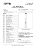
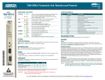
8. HDSL2 DEPLOYMENT GUIDELINES
The ADTRAN HDSL2 system is designed to provide
DS1 based services over loops designed to comply with
carrier service area (CSA) guidelines. CSA deployment
guidelines are given below:
1. All loops are nonloaded only.
2. For loops with 26-AWG cable, the maximum loop
length including bridged tap lengths is 9 kft.
3. For loops with 24-AWG cable, the maximum loop
length including bridged tap lengths is 12 kft.
4. Any single bridged tap is limited to 2 kft.
5. Total bridged tap length is limited to 2.5 kft.
6. The total length of multigauge cable containing
26-AWG cable must not exceed the following:
• 12 - {(3*L26) / (9- LBTAP)} (in kft)
• L26 = Total length of 26-AWG cable
excluding bridged taps (in kft)
• LBTAP = Total length of all bridged taps (in kft)
These deployment criteria are summarized in the chart
shown in Figure 43.
WORKING LENGTH OF 24 GAUGE (OR COARSER) CABLE (KFT)
12
11
INVALID CABLE LENGTHS
Loop loss per kft for other wire is summarized in
Table 6.
Table 6. HDSL2 Loss Values
Cable
Gauge
Cable
Type
Temperature (°F)
68°
90°
26
PIC
3.902
4.051
4.253
26
Pulp
4.030
4.179
4.381
24
PIC
2.863
2.957
3.083
24
Pulp
3.159
3.257
3.391
22
PIC
2.198
2.255
2.333
22
Pulp
2.483
2.545
2.629
19
PIC
1.551
1.587
1.634
19
Pulp
1.817
1.856
1.909
120°
NOTE
These approximations are to be used as guidelines only and may vary slightly on different
loops. Adhering to the guidelines should
produce performance in excess of 10-7 BER.
10
TOTAL
9
2.5
2.0
1.5
1.0
8
7
BRIDGED
TAP
LENGTH
(KFT)
0.5
0.0
6
5
4
3
2
VALID CABLE LENGTHS
1
0
0
1
2
3
4
5
6
7
8
9
WORKING LENGTH OF 26 GAUGE CABLE (KFT)
Figure 43. HDSL2 Deployment Guidelines
30
Issue 1, November 2003
61181113L2-5A
9. TROUBLESHOOTING PROCEDURES
Table 7 is a troubleshooting guide for the Total Access
H2TU-C.
Table 7. Troubleshooting Guide
Condition
Solution
All front panel
indicators are off.
1.Verify that –48 VDC power is
properly connected to the shelf.
2.Insert the H2TU-C into an
operational slot and check the
PWR LED indicators.
3.If Step 1 passes, but Step 2
fails, replace the H2TU-C.
10. MAINTENANCE
The ADTRAN Total Access H2TU-C requires no
routine maintenance. In case of equipment malfunction,
use the front panel bantam jack connectors to help
locate the source of the problem.
ADTRAN does not recommend that repairs be
performed in the field. Repair services may be obtained
by returning the defective unit to ADTRAN. Refer to
Warranty and Customer Service section of this Practice.
11. PRODUCT SPECIFICATIONS
Product specifications are detailed in Table 8.
12. WARRANTY AND CUSTOMER SERVICE
ADTRAN will replace or repair this product within the
warranty period if it does not meet its published specifications or fails while in service. Warranty information
can be found at www.adtran.com/warranty.
USA and Canadian customers can also receive a copy of
the warranty via ADTRAN’s toll free faxback server,
877-457-5007.
Carrier Networks Warranty - Document 414.
Enterprise Networks Warranty - Document 901.
Contact Customer and Product Service (CAPS) prior to
returning equipment to ADTRAN.
For service, CAPS requests, or further information,
contact one of the following numbers:
ADTRAN Sales
Pricing and Availability
(800) 827-0807
ADTRAN Technical Support
Pre-sales Applications/Post-sales Technical Assistance
(800) 726-8663
Standard hours: Monday-Friday, 7 a.m.-7 p.m. CST
Emergency hours: 7 days/week, 24 hours/day
ADTRAN Repair/CAPS
Return for repair/upgrade
(256) 963-8722
Repair and Return Address
ADTRAN, Inc.
CAPS
901 Explorer Boulevard
Huntsville, Alabama 35806-2807
61181113L2-5A
Issue 1, November 2003
31
Table 8. HDSL2 Total Access 3000 H2TU-C Specifications
Specification
Description
Loop Interface
Modulation Type
Mode
Number of Pairs
Line Rate
Baud Rate
Loop Loss
Bridged Taps
Performance
H2TU-C Transmit Power (Data) Level
H2TU-C Transmit Power (Activation) Level
Input Impedance
Maximum Loop Resistance
Return Loss
16 TC PAM
Full Duplex, partially overlapped echo canceling
21
1.552 Mbps
517.333 k baud
Refer to the HDSL2 Deployment Guidelines section for
additional measurements.
Single Taps < 2000 ft., Total Taps < 2500 ft.
Compliant with T1.418-2002 (HDSL Standard, issue 2)
16.6 ±0.5 dBm (0 to 450 kHz)
16.3 ±0.5 dBm (0 to 350 kHz)
135 ohms
900 ohms
12 dB (50 kHz to 200 kHz)
Network Interface
DS1 Transmit Level 0 dB (default), –7.5 dB, –15 dB
DSX-1 Line Buildout 0-133 ft. ABAM (default)
133-266 ft. ABAM
266-399 ft. ABAM
399-533 ft. ABAM
533-655 ft. ABAM
DSX-1 Line Code B8ZS (default), AMI
Power
Tested with the ADTRAN H2TU-C (P/N 1223026L2)
H2TU-C Total Power –48 VDC @ 260 mA with H2TU-R
H2TU-R Power Dissipation 6.6 watts with H2TU-R
Span Power –190 VDC (from H2TU-C) Class A2 Compliant, GFI Current Limited
at <5 mA, Loop Current Limited at between 150 to 160 mA
Fusing 1.00 A (not field-replaceable)
Clock
Clock Sources DSX-1 Derived (with HDSL2 frame bit stuffing) MUX fed
Internal Clock Accuracy ±25 ppm (Exceeds Stratum 4), meets T1.101 Timing Requirements
Tests
Diagnostics Self-Test, Local Loopback (H2TU-C), Remote Loopback (H2TU-R)
Physical
Total Access 3000 H2TU-C, Shelf-Mounted
Dimensions 6 in. High, x 0.7 in. Wide, x 10 in. Deep
Weight < 1 lb.
Environment
Operating Temperature (Standard) –40°C to + 70°C
Storage Temperature –40°C to + 85°C
Compliance
UL 60950; GR-1089-CORE; GR-63-CORE; ANSI T1.418-2002, Issue 2; ANSI T1.102 (DS1 Interface)
Part Number
Total Access 3000 H2TU-C 1181113L2
32
Issue 1, November 2003
61181113L2-5A
Appendix A
HDSL2 Loopbacks
HDSL2 MAINTENANCE MODES
This appendix describes operation of the HDSL2
system with regard to detection of inband and ESF
facility data link loopback codes.
Upon deactivation of a loopback, the HDSL2 system
will synchronize automatically.
Loopback Process Description
In general, the loopback process for the HDSL2 system
elements is modeled on the corresponding DS1 system
process. Specifically, the H2TU-C loopback is similar
to an Intelligent Office Repeater loopback, and the
H2TU-R loopbacks are similar to an in-line T1 Repeater
loopback.
Inband control code sequences are transmitted over the
DS1 link by either the unframed or overwrite method.
The HDSL2 elements respond to either method.
The unframed method produces periodic control
sequences, and the normal DS1 framing bit is omitted.
DDS Latching Loopback Operation
If the unit is optioned for FT1 mode, then DDS Latching
Loopback operation is supported as described in
Bellcore TA-TSY-000077, Issue 3, Section 5.1.3. The
H2TU-C in the HDSL2 circuit is treated as an Identical
Tandem Dataport, and the H2TU-R is treated as a
Different Tandem Dataport. The H2TU-R will establish
a network loopback upon detection of standard DDS
NI-NEI/RPTR loopback sequence.
Loopback Control Codes
A summary of control sequences is given in Table A-1
and Table A-2.
NOTE
In all control code sequences presented, the
inband codes are shown left-most bit transmitted first, and the ESF data link codes with
right-most bit transmitted first.
The overwrite method produces periodic control
sequences. However, once per frame, the framing bit
overwrites one of the bits in the control sequence.
The unit can detect the loopback activation or deactivation code sequence only if an error rate of 1E-03 or
better is present.
61181113L2-5A
Trademarks: Any brand names and product names included in this document are
trademarks, registered trademarks, or trade names of their respective holders.
A-1
Table A-1. HDSL2 Loopback Control Codes
Code2,3
Name
Abbreviated (N)
(N)
(C)
(C)
3in7 (1110000)
4in7 (1111000)
6in7 (1111110)
5in7 (1111100)
Loopback data from network toward network in the HTU-R.
Loopback data from network toward network in the HTU-C.
Loopback data from customer toward customer in HTU-C.
Loopback data from customer toward customer in HTU-R.
Wescom
FF1E (1111 1111 0001 1110)
3F1E (0011 1111 0001 1110)
FF02 (1111 1111 0000 0010)
3F02 (0011 1111 0000 0010)
FF48 (1111 1111 0100 1000)
FF48 (1111 1111 0100 1000)
1 in 3 (100)
FF24 (1111 1111 0010 0100)
Loopback data from network toward network at HTU-C.
Loopback data from customer toward customer at HTU-C.
Loopback data from network toward network at HTU-R.
Loopback data from customer toward customer at HTU-R.
Loopback data from customer toward customer at HTU-R.(FDL)
Loopback data from network toward network at HTU-R. (FDL)
Loopdown everything.
Loopdown everything. (ESF-DL)
Type
1.
2.
3.
A-2
Source1
(N)
(C)
(N)
(C)
(C)
(N)
(N/C)
(N/C)
The Source column indicates which side of the interface the control codes are sent from. For example, an (N) indicates a network sourced code while a (C) indicates a customer sourced code.
All codes are in-band unless labeled FDL.
All codes listed above must be sent for a minimum of 5 seconds to be detected and acted upon.
Issue 1, November 2003
61181113L2-5A
Table A-2. In-Band Addressable Loopback Codes
Function
Code (Hex / Binary)
Response
ARM (in-band) - also
known as 2-in-5 pattern
11000 (binary)
The H2TU-R will loop back toward the network. No AIS or
errors will be sent as a result of this loopback. The H2TU-C
will arm.
Disarm (in-band) - also
known as 3-in-5 pattern
11100 (binary)
The H2TU-C is removed from the armed state. If any of the
units are in loopback when the 11100 pattern is received, they
will loop down. The LBK LEDs will turn off on all units.
H2TU-C Loop Up
D3D3 or
1101 0011 1101 0011
If armed, the H2TU-C will loop back, 2 seconds of AIS (all
ones) will be transmitted, the looped data will be sent for 5
seconds, and then a burst of 231 logic (bit) errors will be
injected. The burst of 231 logic errors will continue every 20
seconds as long as the D3D3 pattern is detected. When the
pattern is removed, the unit will remain in loopback. If the
pattern is reinstated, the injection of 231 logic errors will
resume every 20 seconds.
Loop Down w/o Disarm
9393 or
1001 0011 1001 0011
When sent from the network, all units currently in loopback
will loop down. Armed units will not disarm.
Loopback Query
D5D5 or
1101 0101 1101 0101)
If the units are armed, and the H2TU-C or H2TU-R are in
network loopback, logic errors will be injected toward the
network to indicate a loopback is present toward the network.
The number of errors injected is determined by the unit that is
in loopback. As long as the pattern continues to be sent, errors
are injected again every 20 seconds:
H2TU-C
H2TU-R
Loopback Time Out
Override
D5D6 or
1101 0101 1101 0110
231 errors
20 errors
If the units are armed or a unit is currently in loopback when
this pattern is sent from the network, the loopback time out
will be disabled. As long as the units remain armed, the time
out will remain disabled. When the units are disarmed, the
loopback time out will revert to the previous loopback time
out setting.
If any element is in network loopback a bit error confirmation
will be sent.
H2TU-C
H2TU-R
231 bps
20 bps
Span Power Disable
6767 or
0110 0111 0110 0111
If the units are armed and 6767 is sent from the network, the
H2TU-C will disable span power. If the pattern is sent from
the network, the span power will be disabled as long as 6767
pattern is detected. Once the pattern is no longer received, the
H2TU-C will reactivate span power. All units will then retrain
and return to the disarmed and unlooped state.
H2TU-R Loopback
C742
1100 0111 0100 0010
FDL, ESF only. When set from the network, an H2TU-R
network loopback is activated, and a 20-bit error confirmation
is sent. When set from the customer, an H2TU-R customer
loopback is activated with a 20-bit error confirmation.
Note: All codes listed above must be sent for a minimum of 5 seconds to be detected and acted upon
61181113L2-5A
Issue 1, November 2003
A-3
This page is intentionally blank.
A-4
Issue 1, November 2003
61181113L2-5A
Appendix B
Front Panel DSX and MUX Mode Test Access
GENERAL
Figure B-1 through Figure B-3 are DSX-1 fed modes of
operation, and Figure B-4 through Figure B-7 are MUX
fed modes of operation. From the Provisioning screen
(Figure 13), select “8” to choose the Network Source as
MUX fed or DSX fed. When performing intrusive MUX
mode testing, the equipment jack on the front panel can
be configured to access the signal going to the Network
or the Customer. Select “6” from the Test screen (Figure
17) to configure the equipment jack for Network or
Customer. Every time the HTUC is power-cycled, it
will default to the Customer direction.
DSX MON, RX from Customer
The RX of the BERT receives data from the RX MON
jack (Figure B-2). This data has a monitor jack
impedance of 432 ohms and comes from the Customer
originated data. The BERT TX is not used. This test is
non-intrusive.
DSL
DSX/DS1
ALM
ESF/ SF
(YEL) (GRN)
B8ZS/ALM
(YEL) (GRN)
To MUX
From MUX
LBK
TX
DSX MODE TEST ACCESS
TX
X
DSX MON, TX to Customer
The RX of the BERT receives data from the TX MON
jack (Figure B-1). This data has a monitor jack
impedance of 432 ohms and comes from the Backplane
Network T1 DSX (the data that would go toward the
customer). The BERT TX is not used. This test is nonintrusive.
NOTE
The H2TU-C must be provisioned for the Out
of Service–Maintenance Service State when
intrusive bantam jack testing is being
performed.
RX
To DSX
From DSX
E
Q
RX
432 ‰
TX
M
O
N
To CUST
From CUST
RX
432 ‰
T1 BERT
Figure B-2. DSX MON, RX from Customer
DSX EQ, TX to Customer, RX from Customer
The TX of the BERT goes to the TX EQ jack, and the
RX of the BERT goes to the RX EQ jack
(Figure B-3). The TX EQ data from the BERT is sent to
the Customer. The RX EQ data to the BERT is data from
the Customer. The MON jack TX and RX are 432 ohm
replicas of the EQ TX and RX direct connections. This
test is intrusive, as it connects the EQ jacks directly to
and from the Customer data.
DSL
DSL
DSX/DS1
DSX/DS1
ALM
ALM
ESF/ SF
(YEL) (GRN)
ESF/ SF
B8ZS/ALM
(YEL) (GRN)
(YEL) (GRN)
TX
X
RX
B8ZS/ALM
To MUX
From MUX
LBK
TX
(YEL) (GRN)
TX
To DSX
From DSX
E
Q
RX
RX
TX
To CUST
From CUST
RX
432 ‰
T1 BERT
Figure B-1. DSX MON, TX to Customer
61181113L2-5A
432 ‰
M
O
N
432 ‰
T1 BERT
RX
TX
To CUST
From CUST
RX
To DSX
From DSX
TX
E
Q
432 ‰
M
O
N
To MUX
From MUX
LBK
Figure B-3. DSX EQ, Tx to Customer, RX from
Customer
Trademarks: Any brand names and product names included in this document are
trademarks, registered trademarks, or trade names of their respective holders.
B-1
MUX MODE TEST ACCESS
MUX MON, TX to Customer
The RX of the BERT receives data from the TX MON
EQ jack (Figure B-4). This data is a copy of the data
that the H2TU-C will transmit to the Customer. The TX
of the BERT is not used. This test is non-intrusive.
MUX EQ, TX to Network, RX from the Network
The TX of the BERT is connected to the EQ TX jack,
and the RX of the BERT is connected to the RX EQ jack
(Figure B-6). The TX of the BERT is then substituted
for the data that the H2TU-C sends to the Total Access
Shelf’s MUX (Network). The RX of the BERT receives
data directly from the MUX (Network). The MON TX
and RX jacks are 432 ohm impedance copies of the EQ
jack TX and RX. This test is intrusive.
DSL
NOTE
DSX/DS1
ALM
ESF/ SF
(YEL) (GRN)
To MUX
From MUX
B8ZS/ALM
(YEL) (GRN)
LBK
TX
To DSX
From DSX
TX
X
E
Q
Via the Test screen, ensure that the equipment
jack is in “To Network” mode. In “To Network”
mode, AIS (unframed all 1’s) is sent in the
Customer direction.
RX
RX
432 ‰
TX
M
O
N
To CUST
From CUST
RX
432 ‰
T1 BERT
DSL
DSX/DS1
Figure B-4. MUX MON, TX to Customer
ALM
To MUX
From MUX
ESF/ SF
(YEL) (GRN)
B8ZS/ALM
(YEL) (GRN)
MUX MON, RX from Customer
The RX of the BERT receives data from the RX MON
jack (Figure B-5). This data is 432 ohm copy of the
data that the H2TU-C will receive from the Customer
and route to the Total Access Shelf's MUX (Network).
The TX of the BERT is not used. This test is nonintrusive.
LBK
TX
To DSX
From DSX
TX
E
Q
RX
RX
432 ‰
TX
M
O
N
To CUST
From CUST
RX
432 ‰
T1 BERT
Figure B-6. MUX EQ, TX to Network, RX from
Network
DSL
DSX/DS1
ALM
ESF/ SF
(YEL) (GRN)
To MUX
From MUX
B8ZS/ALM
(YEL) (GRN)
LBK
TX
X
RX
To DSX
From DSX
TX
E
Q
RX
432 ‰
TX
M
O
N
To CUST
From CUST
RX
432 ‰
T1 BERT
Figure B-5. MUX MON, RX from Customer
B-2
Issue 1, November 2003
61181113L2-5A
MUX EQ, TX to Customer, RX from Customer
The TX of the BERT is connected to the EQ TX jack,
and the RX of the BERT is connected to the RX EQ jack
(Figure B-7). The TX of the BERT is then substituted
for the data that the H2TU-C sends to the Customer.
The RX of the BERT receives data directly from the
Customer. The MON TX and RX jacks are 432 ohm
impedance copies of the EQ jack TX and RX. This test
is intrusive.
NOTE
Via the Test screen, ensure that the equipment
jack is in “ To Customer ” mode. In “ To
Customer” mode, AIS (unframed all 1’s) is
sent in the Network direction.
DSL
DSX/DS1
ALM
ESF/ SF
(YEL) (GRN)
B8ZS/ALM
(YEL) (GRN)
To MUX
From MUX
LBK
TX
TX
To DSX
From DSX
E
Q
RX
RX
TX
432 ‰
M
O
N
To CUST
From CUST
RX
432 ‰
T1 BERT
Figure B-7. MUX EQ, TX to Customer, RX from
Customer
61181113L2-5A
Issue 1, November 2003
B-3
B-4
Issue 1, November 2003
61181113L2-5A