1
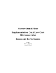
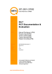
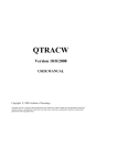
NIDisk
tm
Direct-to-disk Recorder
User Guide
Version 3.03
February, 2007
Revised April, 2007
Engineering Design
This document is provided for the sole purpose of operating the NIDisk system. No part of this
document may be reproduced, transmitted, or stored by any means, electronic or mechanical. It is
prohibited to alter, modify, or adapt the software or documentation, including translating,
decompiling, disassembling, or creating derivative works. This document contains proprietary
information which is protected by copyright. All rights are reserved.
ENGINEERING DESIGN MAKES NO WARRANTY OF ANY KIND WITH REGARD TO
THE MATERIAL CONTAINED HEREIN, INCLUDING, BUT NOT LIMITED TO, IMPLIED
WARRANTIES OF MERCHANTABILITY AND FITNESS FOR A PARTICULAR PURPOSE.
Engineering Design shall not under any conditions be liable for errors contained herein or for
incidental or consequential damages arising from the furnishing, performance, or use of this
material.
The information in this document is subject to change without notice.
© 2001-2007 Engineering Design, Berkeley, CA. All rights reserved.
Printed in the United States of America.
SIGNAL, Real-Time Spectrogram, RTS, Event Detector, Event Analyzer,
Experiment Maker, CBDisk, DartDisk, DTDisk, NIDisk, WaveDisk are trademarks
of Engineering Design.
The following are service marks, trademarks, and/or registered trademarks of the respective
companies:
Communication Automation: Dart
Creative Technology: Audigy, Extigy
Data Translation: Open Layers
Hewlett-Packard: HP, LaserJet, and DeskJet
Measurement Computing Corp: Computer Boards
Microsoft: Windows, Windows 95, Windows 98, Windows 2000, Windows XP
National Instruments: NI-DAQ, NI-DAQmx
Engineering Design
262 Grizzly Peak Blvd
Berkeley, CA 94708 USA
Tel/fax 510-524-4476
Email [email protected]
www.engdes.com
LICENSE AGREEMENT
THIS IS A LEGAL AGREEMENT BETWEEN ENGINEERING
DESIGN AND THE BUYER. BY OPERATING THIS SOFTWARE,
THE BUYER ACCEPTS THE TERMS OF THIS AGREEMENT.
1. Engineering Design (the "Vendor") grants to the Buyer a non-exclusive license to operate
the provided software (the "Software") on ONE computer system at a time. The Software
may NOT reside simultaneously on more than one computing machine.
2. The Software is the exclusive property of the Vendor. The Software and all
documentation are copyright Engineering Design, all rights reserved. The Software may be
duplicated ONLY for archival back-up.
3. The Software is warranted to perform substantially in accordance with the operating
literature for a period of 30 days from the date of shipment.
4. EXCEPT AS SET FORTH IN THE EXPRESS WARRANTY ABOVE, THE
SOFTWARE IS PROVIDED WITH NO OTHER WARRANTIES, EXPRESS OR
IMPLIED. THE VENDOR EXCLUDES ALL IMPLIED WARRANTIES, INCLUDING,
BUT NOT LIMITED TO, IMPLIED WARRANTIES OF MERCHANTIBILITY AND
FITNESS FOR A PARTICULAR PURPOSE.
5. The Vendor's entire liability and the Buyer's exclusive remedy shall be, at the Vendor's
SOLE DISCRETION, either (1) return of the Software and refund of purchase price or (2)
repair or replacement of the Software.
6. THE VENDOR WILL NOT BE LIABLE FOR ANY SPECIAL, INDIRECT, OR
CONSEQUENTIAL DAMAGES HEREUNDER, INCLUDING, BUT NOT LIMITED TO,
LOSS OF PROFITS, LOSS OF USE, OR LOSS OF DATA OR INFORMATION OF ANY
KIND, ARISING OUT OF THE USE OF OR INABILITY TO USE THE SOFTWARE. IN
NO EVENT SHALL THE VENDOR BE LIABLE FOR ANY AMOUNT IN EXCESS OF
THE PURCHASE PRICE.
7. This agreement is the complete and exclusive agreement between the Vendor and the
Buyer concerning the Software.
Table of Contents
1. Overview............................................................................ 1
2. Installation......................................................................... 2
3. Getting Started.................................................................. 4
4. Acquisition ........................................................................ 5
5. Playback ............................................................................ 8
6. Simultaneous Acquisition/Playback ............................... 10
7. Acquisition and Playback Progress Screens ................ 12
8. Acquisition and Playback Triggering ............................. 15
9. Other Functions................................................................ 17
10. Command Line Mode ..................................................... 17
11. Operating Hints and Troubleshooting .......................... 20
12. Technical Notes .............................................................. 24
13. Using NIDisk and SIGNAL ............................................. 26
14. Using NIDisk with RTS ................................................... 28
1. Overview
NIDisktm provides direct-to-disk data acquisition and playback using analog I/O cards from
National Instruments. Program capabilities include:
• Recording up to 8 input channels at up to 1.5 MHz aggregate sample rate
• Playback of 1 or 2 channels at up to 1.5 MHz aggregate sample rate
• Simultaneous recording and playback
• Programmable input gain up to 100 (depending on I/O card)
• Recording and playback can be initiated by external TTL trigger
• TTL output signal provided for synchronization with external systems
• Recording and playback duration up to the capacity of the hard disk
• Record and play sound data in either SIGNAL or Wave file format
• Operates with all current National Instruments desktop and PCMCIA cards
• Runs under Windows 2000/XP
NIDisk supports both desktop and notebook I/O cards. Sample applications include:
• Use with a notebook computer to perform continuous data acquisition in the field up to
ultrasonic frequencies, replacing an expensive ultrasonic or multi-channel recorder
• Use with a notebook computer to perform field playbacks up to ultrasonic frequencies
• Use with a desktop computer to provide an inexpensive I/O workstation for streaming
data collection in the lab, for later analysis in SIGNAL or RTS
NIDisk can store acquired data in either SIGNAL or Wave file format. Both file types can be
read directly into SIGNAL or RTS for display and analysis. Applications for NIDisk sound
files within the SIGNAL family include:
• Review, measure, and edit sound data in the RTS
• Produce continuous spectrograms in SIGNAL
• Automatically analyze recorded files for sound events using the Event Detector
NIDisk User Guide
• Read file segments into SIGNAL for precision display and measurement
NIDisk does not require SIGNAL in order to operate - it can be installed on any Windows
2000/XP computer for stand-alone data acquisition.
NIDisk supports all current analog I/O cards manufactured by National Instruments (NI)
(www.ni.com). These include PCI desktop cards providing 12-bit and 16-bit resolution at
sample rates up to 1.5 MHz, and PCMCIA notebook cards providing 12-bit and 16-bit
resolution at sample rates up to 500 kHz. NIDisk supports full card capabilities, including
maximum sample rate and programmable input gain.
NIDisk has been tested extensively with the 12-bit, 500 kHz PCMCIA notebook analog I/O
card, model DAQCard-6062E and the 16-bit, 1.5 MHz PCI desktop analog I/O card, model
PCI-6251.
2. Installation
To install NIDisk, perform these steps in the following order:
1. Uninstall any obsolete version of the NI-DAQ system driver, if present.
2. Install the NI-DAQmx system driver, which is provided with all NI cards.
3. Install your NI card in the computer.
4. Configure your card in the NI-DAQmx device driver.
5. Install NIDisk.
Uninstall Obsolete NI-DAQ System Driver
NIDisk 3.0 requires NI-DAQmx 8.0 or later. Instructions for uninstalling the NI-DAQ
system driver are provided in Appendix C of the SIGNAL Reference Guide.
If an earlier NI-DAQ version is installed, the NIDisk installer will issue the following
message.
2
NIDisk User Guide
Install NI-DAQmx System Driver and Configure I/O Card
NIDisk 3.0 requires NI-DAQmx 8.0 or later. Instructions for downloading and installing
the NI-DAQmx system driver and configuring the I/O card are provided in Appendix C of
the SIGNAL Reference Guide.
If no NI-DAQ system driver is installed, the NIDisk installer will issue the following
message.
Install NIDisk
Follow these steps to install NIDisk.
1. Launch the file nidisk_xxx_setup.exe (where xxx is the version number) by doubleclicking on the filename in Windows Explorer. If you received a zip file, extract
nidisk_xxx_setup.exe from the zip file, then launch it.
2. Follow the installation prompts.
3. Install NIDisk in the same directory as SIGNAL. The default SIGNAL program
directory is c:\Program Files\Engineering Design\Signal 4.0.
Enable SIGNAL Security Key
NIDisk requires a SIGNAL security key which has been licensed for NIDisk. If NIDisk
reports a non-licensed security key, contact Engineering Design, and the key can be enabled
by email.
3
NIDisk User Guide
NIDisk User Guide
The NIDisk User Guide (this document) is installed as a PDF (Portable Document Format)
file in the \docs directory under the SIGNAL root directory (normally c:\Program
Files\Engineering Design\Signal 4.0). PDF files require the Acrobat Reader program from
Adobe Corporation for viewing. If not already installed, this program is available for free
download at http://www.adobe.com/products/acrobat/readstep.html. Acrobat Reader is also
required by Help | User Guide on the NIDisk menu.
Acrobat Reader provides full text search capability, which can be used like an index, to find
occurrences of a particular word or phrase in the document. To perform a text search, select
Edit | Find in the Acrobat menu.
This guide can be accessed from the NIDisk menu at Help | User Guide.
3. Getting Started
Connecting Signals to the I/O board
See Appendix D, "I/O Hardware Connections" in the SIGNAL Reference Guide for
important notes on connecting signals to the I/O board.
NOTE: if you are running the version of NIDisk which supports high-resolution output
synchronization, you must make certain digital connections in order to perform analog
I/O. See "Triggering an External System from NIDisk" below for details.
NOTE: this capability is not supported in NIDisk 3.0.
Starting NIDisk
To execute NIDisk, do any of the following:
•
Click on the NIDisk desktop icon
•
Select NIDisk from the Start menu or Programs menu
•
In Windows Explorer, navigate to the folder containing the NIDisk executable, then
click on nidisk.exe
To execute NIDisk from a DOS window, select Start | Programs | Accessories | Command
Prompt, change to the folder containing the NIDisk executable (type "cd <foldername>"),
then enter the desired NIDisk command line (see "Command line mode" below).
4
NIDisk User Guide
4. Acquisition
Performing Acquisition
To perform an acquisition, select I/O | Acquire on the NIDisk menu. NIDisk displays the
Acquisition parameter screen, which allows the user to configure the acquisition. NIDisk
then displays the Acquisition summary screen, which summarizes acquisition parameters and
allows the user to initiate the acquisition.
Acquisition Parameter Screen
The Acquisition parameter screen allows the user to specify acquisition duration, sample rate,
input gain, number of channels, the name or prefix, file type, and channel format of the
datafile to receive the acquired data, optional overwrite of pre-existing datafiles, triggering,
and optional alarm sounds. These are described here.
Duration is specified in seconds, and is limited only by the available space on the destination
disk drive. Note: NIDisk does not check for sufficient disk space for your requested
duration. Acquisition length in seconds is related to disk space in MB as follows. For
example, at 250 kHz sample rate, 30 minutes of sound will require 860 MB of disk space.
Disk space in MB = (Acquisition length in secs) * (sample rate in Hz) * (no. channels)
/ 525,000
5
NIDisk User Guide
Sample rate may be selected from the drop list of available sample rates in Hz or entered
manually. Available sample rates vary with the specific I/O card. They are a subset of the
submultiples of some fixed frequency, such as 20 MHz for the PCI-6251. Due to this
mathematics, the drop list typically displays all available high frequency rates and a subset of
the low frequency choices, which are very dense.
Gain sets the gain applied to the input signal before digitizing. Gain is specified as a
multiplier (rather than dB). Available gains vary with different I/O cards.
No. channels can be set to any nymber between 1 and 8. Input sample rate is usually limited
to the maximum sample rate of the I/O card divided by the number of channels. Thus a
500 kHz card can sample two channels at 250 kHz per channel.
Filename specifies the destination sound file. If the filename does not include a full path
(drive letter and directory), files are stored in the directory containing NIDisk. Embedded
spaces are allowed in the filename. NIDisk will append the ".wav" extension to Wave files if
not included.
For a one-channel acquisition, Filename simply specifies the name of the destination sound
file.
For a multi-channel acquisition, the Filename specification depends on the Channel format
setting. With "One file per channel" (the recommended setting), specify the File prefix and
NIDisk will store the data, one file per channel, in SIGNAL files prefix.1, prefix.2, etc. or
Wave files prefix.1.wav, prefix.2.wav, etc. File prefixes should not end with a period (.).
With "Multi-channel file", specify the Filename and NIDisk will store all acquisition
channels in this file (see Channel format). Note that multi-channel SIGNAL files require
SIGNAL 4.1, and Wave files with more than 2 channels may require special software.
File type may be SIGNAL or Wave. Sound data are written as 16-bit integers, coded as
follows. SIGNAL files are strongly recommended.
•
SIGNAL files are written in the native 12-bit or 16-bit coding of the installed I/O
board, with offset removed from 16-bit data. A conversion factor is stored in the file
header that allows SIGNAL to reconstruct the original voltage range.
•
Wave files are written in 16-bit coding (0 offset, ±32768 range), independent of the
installed I/O card. Offset is removed and 12-bit data are scaled to 16 bits. Files are
uncompressed, i.e., in the "PCM" or "type 1" standard Wave file format.
•
Note that Wave file amplitudes may not scale correctly in SIGNAL, since the
Wave header contains no conversion factor to indicate the original voltage range
of the data.
•
Note also that Wave files with sample rates other than 44,100 Hz may not be
playable on all systems.
Channel format indicates how to store multi-channel acquisition data. One channel per file
stores each acquisition channel in a different file (see Filename). Multi-channel file stores
all channels in one file, interleaved, e.g., point 1 of channel 1, point 1 of channel 2, point 2 of
channel 1, point 2 of channel 2, etc. for a 2-channel acquisition.
Overwrite allows NIDisk to overwrite pre-existing data files of the same name without
warning the user. If Overwrite is not checked, NIDisk will request permission before
overwriting.
6
NIDisk User Guide
Triggering allows the user to initiate acquisition manually by clicking OK [Manual] or by
applying an external TTL signal [External], to synchronize with another system. Trigger
polarity indicates whether acquisition will begin on a rising [Low to high] or falling [High
to low] trigger signal. See "External Trigger" below for discussion.
I/O process done produces an alarm sound when the acquisition is done by playing the
sound file IoDone.wav. See "Other Functions" for details.
I/O error produces an alarm sound when acquisition ends in error, by playing the sound file
IoError.wav. See "Other Functions" for details.
I/O overload produces an alarm sound when the input signal overloads the A/D converter by
playing the sound file IoOverload.wav. To avoid auditory runaway on a continuously
overloaded signal, the overload alarm is played no more than once per second. See
"Acquisition / Playback Progress Screen" and "Other Functions" for details.
Acquisition Summary Screen
After closing the acquisition parameter screen, NIDisk displays a summary of the acquisition
parameters, showing the actual sample rate, gain, number of channels, destination
filename(s), required disk space, and other information. NIDisk does not check for
sufficient disk space before acquiring, so be sure the required space is available on the
disk. Acquisition will begin when the user clicks OK (Manual triggering) or after the user
clicks OK and applies the external trigger (External triggering).
7
NIDisk User Guide
5. Playback
Performing Playback
To perform a playback, select I/O | Play on the NIDisk menu. NIDisk displays the Playback
parameter screen, which allows the user to configure the playback. NIDisk then displays the
Playback summary screen, which summarizes playback parameters and allows the user to
initiate the playback.
Playback Parameter Screen
The Playback parameters screen allows the user to specify the file to be played, triggering
mode and optional alarm sounds. Other parameters such as duration, sample rate and number
of channels are predetermined by the sound file. The playback file may be a 1- or 2-channel
SIGNAL or Wave file. Wave files must be stored in uncompressed 16-bit coding (0 offset,
±32768 range), which is the "PCM" or "type 1" standard Wave file format.
Filename specifies the name of the file to be played, including file extension (e.g., myfile.1
or myfile.wav). If the filename does not include a full path (drive letter and directory), files
are played from the directory containing NIDisk. Embedded spaces are allowed in the
filename.
NIDisk accepts SIGNAL integer-format files and Wave files, but not SIGNAL floating-point
format files. SIGNAL files are strongly recommended.
8
NIDisk User Guide
•
SIGNAL files are played at their original voltage range, using a conversion factor
stored in the SIGNAL file header.
•
Wave files are played using an assumed voltage range of ±3 Volts (the default for
Wave hardware), which may or may not be the original voltage range of the data.
To perform a multi-channel playback, submit a multi-channel SIGNAL or Wave sound
file. SIGNAL 4.1 is required to write multi-channel SIGNAL files.
Triggering allows the user to initiate playback manually by clicking OK [Manual] or by
applying an external TTL signal [External], to synchronize with another system. Trigger
polarity indicates whether acquisition will begin on a rising [Low to high] or falling [High
to low] trigger signal. See "External Trigger" below for discussion.
I/O process done produces an alarm sound when the acquisition is done by playing the
sound file IoDone.wav. See "Other Functions" for details.
I/O error produces an alarm sound when acquisition ends in error, by playing the sound file
IoError.wav. See "Other Functions" for details.
I/O overload produces an alarm sound when the input signal overloads the A/D converter by
playing the sound file IoOverload.wav. To avoid auditory runaway on a continuously
overloaded signal, the overload alarm is played no more than once per second. See
"Acquisition / Playback Progress Screen" and "Other Functions" for details.
Playback Summary Screen
After closing the playback parameter screen, NIDisk displays a summary of the playback
parameters, showing the duration, sample rate, number of channels, triggering, source file
name, and file type. Playback will begin when the user clicks OK (Manual triggering) or
after the user clicks OK and applies the external trigger (External triggering).
9
NIDisk User Guide
6. Simultaneous Acquisition/Playback
About Simultaneous Acquisition/Playback
NIDisk can perform simultaneous acquisition and playback when supported by the I/O
device. Simultaneous I/O is supported by most high-performance NI cards, including "Eseries" devices (e.g., DAQCard-6062E) and "M-series" devices (e.g., PCI-6251).
Applications include synchronized stimulus-response experiments and playbacks adapted
dynamically based on vocalization responses acquired during playback.
The acquisition and playback processes must physically start at the same time, but the two
processes can be offset either by inserting silence at the beginning of the playback signal (to
delay playback), or discarding an intial segment of the acquired signal (to "delay"
acquisition). Acquisition and playback processes need not be the same length. The I/O
process will proceed until both acquisition and playback have completed.
To precisely synchronize acquisition and playback processes, use an external trigger (see
below). The status signal IO_ACTIVE (see below) will be driven by the acquisition process.
Only the acquisition progress screen is displayed.
Simultaneous acquisition and playback can be controlled from SIGNAL via the SIMIO
command.
Note that concurrent I/O processes usually divide the bandwidth of the I/O device, e.g., a 500
kHz I/O device will typically support simultaneous one-channel acquisition and playback at
250 kHz per process. The PCI-6251 does not seem to have this limitation, and is capable of
1.5 MHz performance simultaneously on acquisition and playback.
National Instruments I/O devices do not support simultaneous processes of the same type,
e.g., two acquisition processes on the same device.
Performing Simultaneous Acquisition/Playback
To perform simultaneous acquisition/playback, select I/O | Acquire & Play on the NIDisk
menu. NIDisk displays the Acquisition/Playback parameter screen, which allows the user to
configure the acquisition and playback. NIDisk then displays the Acquisition/Playback
summary screen, which summarizes acquisition/playback parameters and allows the user to
initiate the I/O process.
10
NIDisk User Guide
Acquisition/Playback Parameter Screen
The Acquisition/Playback parameter screen allows the user to specify acquisition duration,
sample rate, input gain, number of channels, the name or prefix, file type, and channel format
of the datafile to receive the acquired data, optional overwrite of pre-existing datafiles,
triggering, datafile to be played, and optional alarm sounds. See "Acquisition Parameter
Screen" and "Playback Parameter Screen" for a description of these parameters.
11
NIDisk User Guide
Acquisition/Playback Summary Screen
After closing the acquisition/playback parameter screen, NIDisk displays a summary of the
acquisition/playback parameters, showing the actual sample rate, gain, number of channels,
destination filename(s), required disk space, and other information. NIDisk does not check
for sufficient disk space before acquiring, so be sure the required space is available on the
disk. Acquisition and playback will begin when the user clicks OK (Manual triggering) or
after the user clicks OK and applies the external trigger (External triggering).
7. Acquisition and Playback Progress Screens
During acquistion and playback, NIDisk displays a progress screen containing:
•
Numerical readout of elapsed acquisition time
•
Numerical readout of current signal headroom
•
Graphical bar display of elapsed acquisition time
•
Graphical bar display of current headroom
Click Stop to halt the acquisition or playback before it completes. If acquisition is halted in
this way, sound data recorded up to that point is saved.
The meter also provides a summary display of total I/O time and total headroom when
acquistion or playback has completed. See the figures.
12
NIDisk User Guide
During simultaneous acquisition/playback, only the acquisition progress screen is displayed.
Elapsed Time Display
The meter shows elapsed acquisition or playback time graphically via a real-time linear bar
display and numerical readout. See the figures.
Headroom Display
The meter shows peak signal level graphically via a real-time linear bar display, similar to an
LED-based VU meter on a recording console. See the figures.
Like a VU meter, the display is oriented towards headroom, the parameter of greatest
concern to the recording engineer. Headroom is the dB difference between peak signal level
and the overload level of the A/D converter. Overload level is the converter's maximum
positive code, e.g., +2047 and +32767 for 12-bit and 16-bit converters, respectively. When
headroom decreases to 0, the input signal will be distorted in the A/D.
Headroom is also reported numerically. The operator can monitor display color for an
overview of headroom status and can use the numerical readout to adjust system gain
precisely, so as to maximize the signal-to-noise of the recorded signal without risking
overload distortion.
Display Refresh
During recording, the program updates the entire display every 100 msec, reporting the
worst-case headroom during that interval. Refresh interval represents a tradeoff between a
more responsive meter and system loading at very high sample rates. It may be userconfigurable in a future version.
Meter Color Display
The headroom bar changes color dynamically to indicate headroom status, as illustrated in
the figures:
•
Green = sufficient headroom: headroom > 6 dB
•
Yellow = low headroom: headroom < 6 dB but > 0
•
Red = overload: headroom = 0
Here is the meter during recording with sufficient headroom represented by a green bar:
13
NIDisk User Guide
Here is the meter after recording with low headroom represented by a yellow bar:
and here is the meter during an overload condition represented by a red bar:
Final Meter Display
After recording, the meter reports total headroom, which is the worst-case (minimum)
headroom of the signal during the entire recording. In this way, the operator can always tell
if the A/D has overloaded at any point during the recording without continuously monitoring
14
NIDisk User Guide
the display. The total headroom value is reflected in both the numerical readout and bar
display.
8. Acquisition and Playback Triggering
Triggering NIDisk from an External System
External triggering allows the user to initiate acquisition or playback in NIDisk via an
external control signal, in order to synchronize the NIDisk I/O process with an external
system. For example, an external system might begin neural data acquisition, collect pretrigger data for 5 seconds, then issue a trigger to NIDisk to begin playback stimulation. This
"hardware" triggering provides very high accuracy, typically on the order of 1 microsecond,
which is much more accurate than synchronizing the two systems from the keyboard.
Trigger signal
The external control signal is called EXT_TRIG. National Instruments (NI) boards typically
require a TTL-compatible trigger signal with a minimum duration of 10 nsec. Most NI
boards can trigger on either a rising or falling trigger signal, as specified by the Trigger
polarity parameter. This is useful because some external systems can provide only one type
of polarity. Be sure to consult the trigger specs of your specific I/O board, then confirm
that the external system can output a compatible trigger signal.
Trigger signal latency
Trigger latency is the time delay between the external trigger and the beginning of the
triggered I/O process. It is board-dependent but not CPU-dependent, and is typically < 1
microsecond.
Trigger signal connections
If you have an Engineering Design (ED) I/O panel, connect the external trigger to the TRIG
IN connector on the panel. If your ED panel does not have this connector, contact ED for
modification options.
If you have a National Instruments (NI) I/O panel, connect the external trigger to pin PFI-1.
Triggering instructions
To perform external triggering:
1. Connect the external trigger signal as described above.
2. On the acquisition or playback parameter screen in NIDisk, select External triggering,
then select the trigger polarity.
3. Click OK on the acquisition or playback summary screen. NIDisk will prepare the I/O
process and display a blank Acquiring data or Playing data box.
15
NIDisk User Guide
4. Acquisition or playback will begin on receipt of the external trigger signal.
Triggering an External System from NIDisk
Output triggering allows the user to initiate some process in an external system at the
beginning or end of acquisition or playback in NIDisk, in order to synchronize the NIDisk
I/O process with an external system. For example, the user can start a playback in NIDisk,
then use the output trigger signal to trigger an external neurophysiological data acquisition
system. To gather "pre-trigger" data, insert a segment of silence at the beginning of the
NIDisk playback signal.
Synchronization signal
The output synchronization signal is called IO_ACTIVE. It goes HIGH at the beginning of
the I/O process and LOW at the end of the process. These rising and falling edges can be
used to inform the external system of the beginning and the end of the I/O process. Note:
NIDisk issues synchronization signals only with manual triggering only, not with
external triggering.
Synchronization signal latency
Synchronization signal latency is the time delay between the beginning of the I/O process and
the rising edge of the synchronization signal (and between the end of the I/O process and the
sync signal's falling edge). IO_ACTIVE rises within about 20 microseconds after the
beginning of acquisition or playback, depending on CPU speed (measured with a DAQCard6062E on a Pentium-III/650).
The latency of the falling edge of IO_ACTIVE varies between 70 and 600 microseconds
(measured with a DAQCard-6062E on a Pentium-III/650) on playback. IO_ACTIVE latency
on acquisition has not been measured but is probably similar.
IO_ACTIVE connection
If you have an Engineering Design (ED) I/O panel with the digital I/O option, IO_ACTIVE is
provided at the TRIG OUT connector on the panel. If your ED panel does not have this
connector, contact ED for modification options.
If you are using a National Instruments (NI) I/O panel, IO_ACTIVE is provided at pin DIO0.
16
NIDisk User Guide
9. Other Functions
Alarm Sounds
NIDisk can produce alarm sounds to alert the user to certain acquisition or playback
conditions. These sounds are played through the system sound card, independent of the
NIDisk I/O board. Alaram sounds are stored as Wave files in the NIDisk directory (see
"Acquisition and Playback" for the filenames). Users can customize any sound by
substituting another Wave file of the same name.
I/O Reset
The menu selection I/O | Reset performs a local reset, in case NIDisk malfunctions or stops
responding. It clears NIDisk status variables and status files, and resets the I/O board driver.
If I/O | Reset doesn't solve the problem, follow the troubleshooting steps in "I/O Board Not
Recognized or Not Responding".
User Guide
Select Help | User Guide to display the NIDisk User Guide (this document).
About NIDisk
Help | About NIDisk reports the NIDisk program version, creation date, and the optional
high-resolution version of NIDisk (see "Triggering an External System from NIDisk" above).
10. Command Line Mode
NIDisk can be executed directly from the DOS command line, by including all necessary
parameters with the NIDisk command. NIDisk will bypass the parameter setup screen and
summary screen and begin the I/O process immediately. Only the "Acquiring data" or
"Playing data" screen will be displayed. Command line mode can be used for convenience
17
NIDisk User Guide
(to avoid specifying parameters on the setup screen) and for automation and interfacing with
SIGNAL, as described below.
Command Line Syntax
Following is the command line syntax for acquisition, playback, and simultaneous
acquisition/playback:
nidisk a nchan duration srate gain filetype acqfile [chanform] [trig]
nidisk p playfile [trig]
nidisk s nchan duration srate gain filetype acqfile playfile [chanform] [trig]
where:
A, P, S
nchan
duration
srate
gain
filetype
acqfile
playfile
chanform
trig
= acquisition, playback, or simultaneous acquisition/playback
= number of channels
= recording duration in seconds
= sample rate in Hz
= gain multiplier
= file format: s = SIGNAL, w = Wave
= acquisition filename or file prefix
= playback filename
= [optional] file channel format:
s = one file per channel, m = multi-channel file
= [optional] trigger mode:
manual = keyboard
extlohi = rising edge of external TTL signal
exthilo = falling edge of external TTL signal
Note: other program options can be altered in command line mode. For example, preexisting data files of the same name are overwritten and alarm sounds are played on I/O error
but not on I/O done. If the chanform argument is omitted, all channels are written to one
multi-channel datafile ("m" option). If the trig argument is omitted, manual triggering is
assumed. If the file format is "one file per channel", filename should contain the file prefix;
otherwise filename should contain the full filename. See "Acquisition Parameter Screen"
above for details.
Examples:
nidisk a 2 60 50000 10 s myAcqFile
will acquire two channels for 60 seconds at 50 kHz sample rate per channel with a gain
multiplier of 10, to a two-channel SIGNAL-format sound file called myAcqFile.
nidisk p myPlayFile
will play the sound file myPlayFile, which may contain 1 or 2 channels.
nidisk a 2 60 50000 10 s myAcqFile s
will acquire to two SIGNAL-format sound files called myAcqFile.1 and myAcqFile.2.
nidisk s 2 60 50000 10 s myAcqFile myPlayFile
18
NIDisk User Guide
will acquire two channels for 60 seconds at 50 kHz sample rate per channel with a gain
multiplier of 10, to a two-channel SIGNAL-format sound file called myAcqFile, while
simultaneously playing the sound file myPlayFile.
If the filename or filename prefix includes embedded spaces, enclose the entire name in
quotation marks, for example:
nidisk a 2 60 50000 10 s "\my project\myfile"
Calling NIDisk from SIGNAL
NIDisk can be called from SIGNAL using the EXEC command. Include the full pathname of
the NIDisk executable, and enclose this in quotes if it contains embedded spaces, as in the
example below. Two applications are: 1) enclosing NIDisk in a SIGNAL program loop to
automate and time repetitive playbacks (using DOLOOP and TWAIT), and 2) using TWAIT
to run NIDisk at a particular time of day, for scheduled recording. The following example
(which should be presented on a single line) will perform the acquisition described above:
EXEC "c:\Program Files\Engineering Design\Signal 4.0\nidisk"
a 2 60 50000 10 s "\my project\myfile"
Calling NIDisk from DOS
A NIDisk command can also be run from a DOS batch file. This avoids entering parameters
manually into the parameter setup screen, to perform the same process repeatedly. Create a
one-line .bat file containing the command line text, such as "nidisk a 2 60 50000 10 s myfile"
without the quotes. Then either 1) double-click on this file in Windows Explorer, or 2) open
a DOS window (in the Start menu, click Programs | Accessories | Command Prompt) and
type the .bat file name.
Status File
NIDisk writes acquisition and playback status files to enable communication with a calling
program. These files are called NIDiskAcqStatus.txt and NIDiskPlayStatus.txt, and are
located in the NIDisk program directory. These files contain one line in the format
status=status
where status is the status of the current or just-completed I/O process:
ACTIVE
DONE
ABORTED
ERROR
= in progress
= successfully completed
= aborted by the user
= terminated by the program due to error
Normally, status will be ACTIVE during acquisition or playback and DONE after the I/O
process completes. The user can call NIDisk from SIGNAL, then poll the status file (using
19
NIDisk User Guide
RA family commands) to determine when the I/O process has completed and whether it was
successful.
11. Operating Hints and Troubleshooting
Following are operating hints and troubleshooting guidelines for the NIDisk system.
None or Obsolete NI-DAQ System Driver Installed
NIDisk 3.0 requires NI-DAQmx v8.0 or later. If this version is not installed, NIDisk will
issue the following message on startup. Instructions for downloading and installing the NIDAQmx system driver are provided in Appendix C of the SIGNAL Reference Guide.
NIDisk Program Already Active or Terminated Abnormally
NIDisk may issue the following message on startup. This can occur if another NIDisk
program is running, or if a previous NIDisk process terminated abnormally and is running
invisibly. To check for an invisible NIDisk, open Task Manager (Ctl-Alt-Del), search for
nidisk.exe, and terminate the process if present. If this does not correct the problem, follow
the steps in "I/O Device Not Recognized or Not Responding".
I/O Device Not Recognized or Not Responding
The I/O device not responding can be due to many causes at different system levels, such as
board standby state, board initialization, driver initialization, operating system state, and
corruption of the board driver or I/O driver. The following sequence of steps descending
downward through the system levels, beginning with NIDisk reset and ending with software
reinstallation. These should be followed in the order given.
20
NIDisk User Guide
1. If the I/O device is not present or is not named "Dev1", NIDisk issues the following
message:
If the device is not present, install it as described in Appendix C of the SIGNAL
Reference Guide. If it is present, open Measurement & Automation Explorer (MAX)
as described under "Confirm and troubleshoot I/O card and driver installation" in
Appendix C and verify that the device is named "Dev1" (see figure). If not, R-click
and rename.
2. If the I/O device is present but NIDisk does not recognize it, NIDisk issues the
following message:
Removable I/O devices, such as PCMCIA cards and USB units, usually need to be
removed and reinserted after the system is restored from Standby, even though
Device Manager may report the device as installed and "working properly". If
the I/O device is removable, remove and reinsert the device. If NIDisk still does not
recognize the device, proceed to step 4.
3. If NIDisk recognizes the I/O device but will not perform I/O operations, select I/O |
Reset on the menu to reset NIDisk status. See "I/O Reset". If NIDisk still will not
perform I/O operations, proceed to the next step.
21
NIDisk User Guide
4. If NIDisk has (or may have) terminated abnormally, it may be running as a
"phantom" process and preventing other NIDisk processes from operating correctly.
To check this in Windows XP, open Windows Task Manager by hitting Ctrl-Alt-Del,
select the Processes tab, and click Image Name to view the task names in alphabetical
order. Select each "nidisk.exe" task and click End Process to terminate it. Then
launch NIDisk again. If NIDisk still will not perform I/O operations, proceed to the
next step.
5. Run Measurement & Automation Explorer (MAX) and perform the troubleshooting
steps described in "Confirm and troubleshoot I/O card and driver installation" under
"National Instruments" in Appendix C of the SIGNAL Reference Guide. If MAX
does not recognize the device or reports a problem, proceed to the next step.
6. Reboot the computer, then run MAX again. If MAX still reports a problem, proceed
to the next step.
7. Uninstall and reinstall the National Instruments system driver and board driver for the
I/O device, as described under "National Instruments" in Appendix C of the SIGNAL
Reference Guide.
Minimum and Maximum Duration
Minimum acquisition and playback duration is 0.1 seconds. Maximum acquisition and
playback duration is the capacity of the hard disk.
Minimum and Maximum Sample Rate
Minimum sample rate is 100 Hz for acquisition and playback. Maximum sample rate is
determined by the analog I/O card. NIDisk has been tested with a 12-bit, 500 kHz PCMCIA
notebook analog I/O card (model DAQCard-6062E) and a 16-bit, 1.5 MHz PCI desktop
analog I/O card (model PCI-6251). See "Technical Specifications" for more detail.
I/O Errors
Acquisition and playback errors arise when the I/O board cannot convert data, or when
NIDisk cannot cannot store or retrieve data from memory or the hard disk, at the requested
sample rate. NIDisk will issue messages similar to the following. Possible causes include
performing demanding processes in parallel with NIDisk, a slow CPU, or a slow hard disk.
Remedies are to terminate other processes, defragment the hard disk, increase CPU or disk
capabilities, or reduce sample rate.
Following are two sample acquisition error messages (the verboseness is from the
manufacturer, not NIDisk!):
22
NIDisk User Guide
Disk Fragmentation and Maximum Sample Rate
On older hard disks, fragmentation can degrade the maximum sample rate. Disks can be
defragmented by clicking My Computer | Local Disk | Properties | Tools | Defragment Now.
This process should be performed with care, and a full backup is recommended before
degragmenting.
Notebook Power Management
Some notebook computers (such Toshiba models) optionally reduce processor speed when
running from batteries, to conserve battery life. This can severely reduce the maximum
achievable sample rate. To avoid this, reconfigure the computer’s power management
program (usually available from the Control Panel) to run at full processor speed on battery
power.
As an example, following are steps for reconfiguring a Toshiba Satellite 2250CDT: 1) run
Power Saver from the Control Panel (not the Windows-supplied Power Management utility),
2) in the "Running on batteries" section, set the power mode to High Power, 3) click Details,
23
NIDisk User Guide
select the Power Save Mode tab, and move the 4 slider controls associated with Processor
Speed to Full, 4) click OK.
Running the PCMCIA Card from a Desktop Computer
A PCMCIA card can be run from a desktop computer using a PCMCIA to PCI adapter card.
This card costs approximately $200 and can allow the card to do "double duty", for example,
in a desktop workstation in the lab and in a notebook computer in the field. Contact
Engineering Design for the currently recommended adapter.
Portability to All National Instruments Analog I/O Cards
NIDisk operates with all National Instruments analog I/O cards. NIDisk automatically makes
the installed card's capabilities available, including maximum sample rate and programmable
input gain.
Running NIDisk with Multiple NI I/O Cards Installed
If you have multiple NI I/O cards installed in your computer, the Measurement &
Automation Explorer program (MAX) will name them by default "Dev1", "Dev2", etc.
NIDisk will always select "Dev1". To access a different NI device, rename the devices (Rclick on the device name in MAX and select Rename) so that the desired device is "Dev1".
Device names are retained when an I/O card is removed from the computer.
Examining NIDisk Output in SIGNAL
By default, NIDisk stores acquired sound files in the directory containing the NIDisk
executable. If in doubt about the location of NIDisk output files, select Search | For Files and
Folders on the Windows Start menu.
12. Technical Notes
Technical Specifications for NIDisk with DAQCard-6062E
Following are technical specifications of the NIDisk program, operating with the DAQCard6062E analog I/O card.
Input characteristics
Maximum channels
24
8
NIDisk User Guide
Minimum sample rate
Maximum sample rate
Programmable gain
100 Hz
500 kHz
1, 2, 5, 10, 20, 50, 100
Impedance
Noise (re max signal level)
THD
100 G-ohm in parallel with 100 pF
n/s
n/s
Output characteristics
Maximum channels
Minimum sample rate
Maximum sample rate
Impedance
Noise (re max signal level)
THD
Input/output characteristics
No. sample rates
Maximum signal level
Maximum signal length
2
100 Hz
500 kHz
< 0.1 ohm
n/s
n/s
> 1000
± 10 Volts
Limited by physical disk size
Digitizing resolution
Converter type
Anti-alias filter
12-bit = 72 dB
Linear
Not included
Triggering
Trigger latency
Synchronization
Synchronization accuracy
Software / external TTL
< 1 microsec
TTL
< 1 microsec
[w/ special I/O panel]
n/a = not applicable, n/s = not specified
Bandwidth Limitations of PCI-6251
This section discusses the acquisition bandwidth (BW) of the PCI-6251 and the conditions
under which that BW can be extended in practice. The NI-specified BW of the 6251 is 1.25
MHz single channel and 1.0 MHz multi-channel.
Acquisition Settling Time
The acquisition BW of a digitizing board is limited by the settling time of its input amplifier,
which is the time required for the amplifier to register the voltage change between successive
input samples to a certain accuracy. Because there is only one input amplifier, successive
samples may come from a single channel or consecutive channels in multi-channel mode. If
25
NIDisk User Guide
the input signal is V(t) = A sin 2πft, then voltage change is dV/dt = 2πfA cos 2πft, whose
maximum = 2πfA Volts/sec. So instantaneous voltage change depends on the product of
input amplitude (A) and frequency (f) and will be greatest for a full-scale input signal of
maximum (Nyquist) frequency.
Under these worst-case conditions, and for input gains between 1 and 10, NI-specified
settling time is 1 usec to 12 bit accuracy and 1.5 usec to 16 bit accuracy. Thus at unity gain
(10 Volt range), a 10-Volt input signal at Nyquist frequency requires 1.5 usec to settle to 16bit accuracy. Smaller signals require less time to settle; for example, a 0.5-Volt input signal
acquired at unity gain has only 12 bits to settle and requires closer to 1 usec for a 50% greater
BW. NI-specified maximum "small-signal" BW is 1.7 MHz, a settling time of 0.6 usec.
Acquisition Crosstalk
Settling affects multi-channel operation via the voltage difference between successive
channels. As total channel BW approaches the board's BW capability, the input amplifier
does not have time to settle between successive channel samples, and carries the value from
one channel into the next. This artifact is called crosstalk and is defined as the ratio of
amplitude induced in one channel by a signal in another. Crosstalk is measured by shorting
the target channel input, applying a full-scale signal to the previous channel, and measuring
leakage into the target channel. NI specifies worst-case crosstalk as -75 dB, but measured
performance exceeds that.
The following table summarizes measured crosstalk vs. total bandwidth = (sample rate) *
(no. channels), and can be used to limit board operation according to desired accuracy.
Measurements were made with 8-channel operation.
Crosstalk level
-87 dB
-65 dB
-47 dB
-20 dB
Bandwidth
1.00 MHz
1.33 MHz
1.43 MHz
1.54 MHz
For example, if the board is operated at 1.33 MHz (e.g., 8 channels at 167 kHz sample rate),
crosstalk will be -65 dB, limiting accuracy to about 11 bits, which is acceptable for many
biological applications, while at 1.43 MHz (8 channels at 178 kHz), crosstalk is -47 dB.
13. Using NIDisk and SIGNAL
NIDISK can be used in conjunction with the SIGNALtm sound analysis program to record
extended acoustic data sequences, then locate and analyze the sound events within them.
This section describes the overall approach, basic tools, and important information sources.
The two programs work together as follows:
•
26
NIDisk provides long-duration high-frequency direct-to-disk recording, producing long
continuous sound files in the SIGNAL or Wave sound file format.
NIDisk User Guide
•
SIGNAL can display the entire sound file (see below), which the researcher can use as a
roadmap to extract specific sound events. SIGNAL can manually extract, display,
measure, and analyze these events and store them as individual sound files. SIGNAL can
also be programmed to perform acoustic measurements automatically on the stored
events.
Subject
Microphone
Continous sound spectrogram
in SIGNAL using STRIP
Record sound file in NIDisk
Edit and measure sound
events in SIGNAL
The above figure illustrates this process. Following is an overview of the steps involved.
1. Present the acoustic vocalization stream to the microphone or hydrophone.
2. Connect the microphone or hydrophone to the NIDisk input panel.
3. Use NIDisk to digitize and record the vocalization stream to one or more continuous
sound files. Normally, set the NIDisk sample rate to at least 2.5 times the desired
recording bandwidth.
4. Start SIGNAL and use the STRIP command to view a continuous spectrogram of the
recorded sound file. STRIP produces a multi-screen "strip-chart" frequency-time
27
NIDisk User Guide
spectrogram with typically 30-60 seconds of sound per screen. This allows the user to
navigate through a long recording, spotting sound events and extracting them for detailed
analysis. Settings such as frequency range and spectrogram resolution can be used to
customize the display. Note: STRIP settings can be collected in a SIGNAL macro for
convenience.
5. After using STRIP to review the sound file and locate vocalization events, read individual
events into SIGNAL using the R /Q command.
6. Use SIGNAL to measure and analyze the sound events. Events can also be saved on disk
as individual sound files if desired.
7. SIGNAL can be programmed to perform many acoustic measurements automatically on
an entire group of sound files. See the programming chapters in the SIGNAL User
Guide
14. Using NIDisk with RTS
NIDISK can be used together with the Real-Time Spectrogramtm (RTS) program to record
and visually review, measure, and edit extended acoustic data sequences up to hours in
length. The two programs work together as follows:
•
NIDisk can digitize an entire data tape to a sound file, or perform direct-to-disk
recording, bypassing the tape entirely.
•
RTS can rapidly page or scroll through the sound file on-screen, while measuring,
extracting, and storing sound parameters and sound segments directly from the screen.
Navigating a sound file on disk is much more efficient than playing, pausing, and
replaying from a tape player!
The RTS can scroll or page rapidly forward or backward through a sound file to search for
events interest. For example, the following 30-second sample screen was scrolled in 3
seconds – a review rate of 10 times real-time! The user can also page through the sound file
in either direction at 15 times real-time.
28
NIDisk User Guide
The wide screen and high-resolution spectrogram of the RTS can be used to locate events in
sparse data sets. For example, the sparse sound file in the following figure was displayed in
5-minute segments, in which the 3 events are clearly visible. With 3 seconds to draw or
scroll a new screen, this allows sparse data sets to be analyzed at 100 times real-time. Once
located, individual events can be zoomed for close examination.
29
NIDisk User Guide
The RTS runs within SIGNAL, so sound segments can be transferred easily to SIGNAL
buffers for immediate analysis, and measured sound parameters can be stored in the SIGNAL
logfile. In the following figure, the RTS has saved 6 events in SIGNAL buffers and 11
measurement records have been stored in the SIGNAL logfile. Events can also be stored as
SIGNAL, Wave, or AIFF sound files for later analysis.
30