1
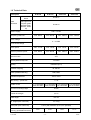
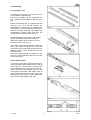
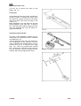
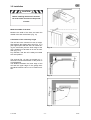
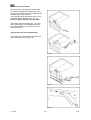
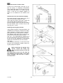
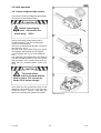
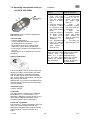
Instruction manual
Sensor-Line S 401
Please keep this manual in a safe place.
GB
B 190.028-GB
S 401 GB
-1-
03-06
Index
1.0 Technical Data .................................................................................................... 3
2.0 General Instructions........................................................................................... 4
2.1 General safety instructions................................................................................ 4
2.2 Designated use ................................................................................................. 4
2.3 Indication for operating...................................................................................... 4
3.0 Drive assembly ................................................................................................... 6
3.1 Scope of supply................................................................................................. 6
3.2 Required tools ..................................................................................................... 6
3.3 Installation requirements ....................................................................................... 6
3.4 Assembly ............................................................................................................ 7
3.5 Installation......................................................................................................... 9
3.6 Initial operation................................................................................................ 13
3.6.1 Insert red/green light module.................................................................... 13
3.6.2 Functions and connections....................................................................... 14
3.6.3 Set-Up ...................................................................................................... 15
3.6.3.1 Adjustment of force and travel ........................................................................15
3.6.3.2 Individual adjustments.....................................................................................15
3.6.4 Perform safety check................................................................................ 18
3.6.5 Warning notices........................................................................................ 18
3.6.6 Radio ........................................................................................................ 18
3.6.6.1 Installation of the radio ....................................................................................18
3.6.6.2 Set-Up of the radio .........................................................................................18
3.6.6.3 Testing the radio .............................................................................................18
4.0 Maintenance...................................................................................................... 19
5.0 Demounting and disposal................................................................................ 19
6.0 Failure analysis................................................................................................. 20
7.0 Operating Instructions radio system PICO, 868,5 MHz ................................. 21
8.0 TÜV-Certificate.................................................................................................. 22
9.0 TÜV-Doors......................................................................................................... 22
10.0 EC-Manufacturer's Declaration ..................................................................... 23
11.0 EC- Manufacturer’s Declaration according to EC Directive........................ 24
12.0 Handing over................................................................................................... 24
S 401 GB
-2-
03-06
1.0 Technical Data
Description
head
variations
S 401-60
S 401-80
standard circuit
board
optional red /
green light module (red / green
light red/ green,
230VAC, 50Hz,
1A)
S 401-120
B 300.01
B 300.04
electric supply
temporary peak load
S 401-100
230 V / 50 Hz
max. 600 N
max. 800 N
max. 1000 N
max. 1200 N
motor voltage
0 – 24 VDC
circuit board voltage
motor power
max. 110 W
max. 120 W
max. 150 W
max. 180 W
tractive- /pressure power
max. 600 N
max. 800 N
max. 1000 N
max. 1200 N
switch-on-time
30%
speed (without load) max.
14cm/sec
lighting
40W/230V (E14)
duration of lighting
30-180 sec
Radio (standard delivery)
868,5 MHz
ambient temperature
-20°C/ +40°C
idle running – power loss
fusible cut-out
<1W
F1:3,15AT/250V F1:3,15AT/250V F1:3,15AT/250V F1:3,15AT/250V
F2:6,3AT/250V F2:6,3AT/250V F2:10AT/250V F2:10 AT/250V
minimum mounting height
35 mm
overall drive length
3,31 m
head height
145 mm
ca. weight (with 3,00m rail)
ca. 18 kg
travel path (with 3,00m rail)
2,40 m (with extension up to 5,4 m possible)
max. area of door (smooth
running, good balanced doors)
S 401 GB
8 m²
10 m²
-3-
12 m²
14 m²
03-06
You have to pay attention that the relevant national VDE-regulations for operating electrical
appliances are strictly adhered to.
We do not take any responsibility for the improper operating or maintenance of the door,
accessories and the opener.
2.0 General Instructions
This instruction manual is being released by
BERNAL without any warranty.
BERNAL reserves the right to make changes
or modifications on the equipment at any time
and on this manual without giving any prior
notes.
2.2 Designated use
The garage door opener is designed only for
the operation with well-balanced swing- and
sectional doors in the non-commercial sector.
The recommended max. door measurements
are listed under 1. Technical Data. The door
has to be in accordance with the valid specifications (e.g. DIN EN 12604 and DIN EN
12605). Before mounting the opener, check
that the door can to be easily moved by hand.
2.1 General safety instructions
Important Safety Instructions:
FOR THE SAFETY AND LIFE OF PERSONS IT IS ABSOLUTELY NECESSARY
TO FOLLOW ALL INSTRUCTIONS.
The opener is designed for the operation in dry
rooms.
KEEP THESE INSTRUCTIONS
The garage ceiling has to be constructed, so
that a safe attachment of the opener is assured.
Qualified personnel should only
perform the assembly and installation of the garage door opener.
Faulty installation may lead to serious injuries! Disconnect power plug before any
work on the device is done. (except on test
and learning procedures) !
2.3 Indication for operating
For garages without a second entrance, a
emergency release is necessary. A function
test of the emergency release has to be carried out monthly!
On installation the relevant regulations for the operational safety act
/ employers mutual insurance association have to be followed, e.g. UVV, DIN
EN 60335-1 and VBG4.
Do not hang on the cord of the emergency release with your weight!
Make sure, that the emergency release of the
opener does not collide with the roof rack or
any protrusions of the vehicle or the door.
The electro installation has to be
performed by a qualified electrician, and has to conform to the
relevant industrial safety regulations, according to DIN VDE 0100 and DIN VDE 0113.
The power point must be easily accessible
and at a max. distance of 50cm from the
opener head.
Instruct all persons, who are using the garage door and opener, about a safe and
proper handling. Demonstrate and test the
reversion (with a 50 mm high obstacle at
max. 150 N) as well as the mechanical
unlocking.
Do not operate the garage door
opener at all, until it is confirmed,
that the garage door is in accordance with the safety norm 98/37/EG and a
valid EC-Declaration of Conformity certificate is issued.
.
Operate the door only, when you can see
the whole door area unobstructed. Pay attention, that there are no persons or any
objects in the door operating area.
Wait until the door stands still. Persons or
vehicles are only allowed in door operating
area, when the door is completely open and
at standstill.
An improper installation or any change to the
opener without the manufacturers previous
approval, any warranty or product liability is
null and void. The installation has to be performed in accordance with this instruction. The
installation of foreign elements endangers the
safe operation of the opener and is not permitted.
S 401 GB
-4-
03-06
Do not permit children to
play with the automated garage door. Transmitters are
to be kept safe and away
from children !
Fixed accessories (like key switch or similar) have to be attached in sight of the door.
The accessory distance to the moving parts
of the door, and at a minimum mounting
height of 1,80m. Accessories have to be installed beyond the reach of children! Alert
stickers against pen in have to be put close
to the fixed key switch.
Door, opener and extra installed safety accessories have to be checked regularly.
See chapter 4 maintenance.
Attention:
The door can shut down faster with weak,
broken or damaged springs or a defective
counterweight. Under this circumstances
using the emergency release may lead to
uncontrolled movements of the door.
When service- or adjustment work is urgently required, do not use the opener . A
badly balanced door, or a faulty garage
door drive may cause damage and injuries.
S 401 GB
-5-
03-06
3.0 Drive assembly
CAUTION
IMPORTANT INSTRUCTIONS FOR A
SAFE MOUNTING
ATTENTION – INCORRECT MOUNTING
MAY LEAD TO SERIOUS INJURY – ALL
MOUNTING INSTRUCTIONS HAVE TO
BE FOLLOWED
Fig.1
3.1 Scope of supply
The scope of supply, as shown on the Fig. 1
and 2, may vary according to the drive version.
3.2 Required tools
For the assembly und mounting of the drive
the tools shown in Fig. 3 are required (not in
the scope of supply).
Fig. 2
3.3 Installation requirements
The garage door opener is suitable for the
automation of spring balanced swing doors
(Fig. 4a) and sectional door (Fig. 4c).
(max. sizes see 1.0 technical data).
For an optimal attachment of the push rod to
the sectional door, a sectional door attachment
is available as an accessory.
For doors, that are non-protruding up-andover, a curved arm is available as accessory.
(Fig. 4b)
For the mounting a minimum lintel height of 35
mm is necessary (Fig. 4).
Fig. 3
Fig. 4
S 401 GB
-6-
03-06
3.4 Assembly
Pre-assembly of rail
According to the version, the rails have to be
pre-mounted as requirements.
Put the rails together via the connection rail.
(Fig. 5) Slide the rails together to the stop position.
Pull the rear bracket (Fig. 6.1) together with the
belt (Fig. 6.2) out of the rail. Remove the
transportation covering (Fig. 6.3) and press the
pinion (Fig. 6.4) into the bearing. Take care of
the belt not being squeezed. Then attach the
transportation covering again and push the
complete rear bracket back into the rail.
Fig. 5
Adjust the tension of the chain or belt by pulling the idler wheel towards the chain end.
Make sure, that the chain lock (Fig. 7a) is on
the left side of the rail. (Fig. 7)
Then push the tensioning bracket towards the
end of the chain and guide the coach bolt
through the hole of the tensioning bracket. Pay
attention that the coach bolt fits into the tensioning bracket.
Push the provided spring and washer on the
end of the coach bolt and screw the nut on the
coach bolt. (Fig. 8)
Fig. 6
Paste rubber buffers
If you have a chain drive, we recommend sticking the provided rubber buffers to the inside of
the rail (Fig. 9c). Those serve to minimize the
noise caused, when the chain touches the rail.
Assure, that the rubber buffers are not in the
travel path of the trolley. The buffers have to
be put close to the end of the chain, so that the
trolley doesn’t touch them in door-closed- (Fig.
9a) or in door-open-position (Fig. 9b).
Fig. 7
Fig. 8
Fig. 9
S 401 GB
-7-
03-06
Pre-tension chain / belt
Turn the nut to tension the chain or belt
slightly. Fig. 10).
Trolley test
Check afterwards, that the trolley can easily be
moved by hand. To release the trolley, from
the chain lock, pushes the lever on the trolley
and at the same time move the trolley in the
rail (Fig. 11).
Make absolutely sure, that after this test the
trolley engages on the chain lock. To perform
this, move the trolley without holding the lever
over the chain/belt lock and the trolley engages automatically.
Fig. 10
Assembly of door bracket
According to the installation situation the provided push rod components can be combined
as needed (Fig. 12).
If the length of the push rod is not sufficient, it
can be adjusted via the extension rod (Fig.
12a). In adoption with sectional doors, we recommend the use of a sectional door angle
(Fig. 12c). Then the provided door bracket
(Fig. 12b) has to be attached to the push rod.
For the assembly use the provided screws,
washers and nuts, and tighten them firmly.
Fig. 11
Fig. 12
S 401 GB
-8-
03-06
3.5 Installation
CAUTION
Before installing the drive all mechanical locks of the door have to be put out
of order!
Mark the middle of the door
Measure the width of the door and mark the
middle of the door at the lintel. (Fig. 13)
Calculation of the necessary height
The rail has to be mounted on such a height,
that between the highest door point (Fig. 14.1)
(the highest point that the door can reach during the movement) and the lower edge of the
rail, a clearance of at least 10-20 mm is available (Fig. 14.2).
Pay attention, that the rail is always mounted
at a level position.
Fig. 13
The angle a (Fig. 15) may not exceed 30°; otherwise a correct transmission of the power is
not guaranteed.
The distance between the lower edge of the
rail and the upper edge of the garage door
should be between 5 and 7 cm in closed condition.
Fig. 14
Fig. 15
S 401 GB
-9-
03-06
Mounting the lintel bracket
Extend the door measurements on the lintel,
so that the provided head bracket (Fig. 16) is
exactly in the middle of the door and above the
required highest door position.
Use a pen and mark the bracket holes on the
lintel and drill the required holes (Fig. 16).
Attention: When drilling, cover the drive!
Then attach the lintel bracket (Fig. 17) to the
lintel. (depending on the installation situation
the provided fastening screws have to be replaced by others).
Attaching the rail to the head bracket
Then fasten the rail to the lintel bracket with a
coach bolt and a lock nut (Fig. 18).
Fig. 16
Fig. 17
Fig. 18
S 401 GB
- 10 -
03-06
Fixing of the retaining angle
Bring the rail in a level position, fit the retaining
angles to the return head. Make sure, that the
rail is in a level position. The excess lengths of
the angles have to be sawed off (Fig. 19).
Attachment of the rail
Afterwards mark the points where the retaining
angles shall be attached to the ceiling. Make
sure, that the rail is aligned with the earlier
marked middle of the door.
Drill the required holes and affix the retaining
angles to the ceiling (Fig. 20.1).
Attention: When drilling, cover the drive!
Attachment of the drive head
The next step is to insert the drive head shaft
on the collet of the return head (Fig. 20.2).
As shown in Fig. 20.3 the drive head has to be
attached with the 2 Phillips-screws and spring
washers to the return head.
Fig. 19
Abb. 20.1-20.3
S 401 GB
- 11 -
03-06
Adjust the tension of chain or belt
Turn the nut of the tension unit (Fig. 21), so
that the spring is completely compressed.
Than release the tension of the spring by turning the nut back about 1 to 2 turns, until the
chain or belt can be pushed together to
approx. 0,5 cm distance in the middle of the
rail.
Attachment of the door bracket assembly
First press the lever on the trolley, (Fig. 22.1)
and move the trolley towards the lintel.
Then mark the points of the door, where the
door bracket shall be attached (Fig. 22.2).
Drill the required holes at the door and attach
the door bracket, with 2 screws, firmly to the
door (Fig. 22.3 + 22.4).
Fig. 21
Installing the emergency release
If the garage is without a second entrance, the
installation of a emergency release set is absolutely necessary, so that in case of an emergency the door can be opened from outside.
The Bowden cable has to be moved through
the eye of the „key shaft“ and the mantle.
(Fig. 23.1 + 23.2) Afterwards the linkage has to
be moved through the door bracket (Fig. 23.2).
At the end of the installation of the Bowden
cable has to be attached at the door handle
(Fig. 23.3).
It is absolutely necessary, to check the correct
function of the emergency release, before using the garage door opener.
Fig. 22
Before operating the garage door
opener: unlock the trolley and
open and close the door to the full
stop by hand.
The trolley has to come to a full stop, before bumping the drive head or the return
guide assembly, with the door in open /
closed position.
Fig. 23
S 401 GB
- 12 -
03-06
3.6 Initial operation
3.6.1 Insert red/green light module
If you want to insert the red/green light module,
you have to do the following steps:
CAUTION
Before removing the
light cover - disconnect the
power plug!
230V ~
At first, the 2 safety screws have to be removed as shown in Fig. 24.1 and the light
cover has to be taken off.
Then turn out the light bulb and the 4 screws of
the cover (Fig. 24.2).
Now the cover can be taken off (Fig. 24.3) and
the red/green light module can be inserted
(correct position see Fig. 25 circuit board layout).
The red/green light module has to be attached
with the provided screws on the circuit board,
and the heads of the screws have to be isolated with the provided plastic covers (Fig.
24.4).
CAUTION
The heads of the
screws must be isolated with the
plastic covers. The screws are
under 230 V mains voltage!
Then break out the pre-punched notch for the
red/green light module in the cover and reassemble the cover – screws – light bulb and
light cover. Now plug the opener to the mains.
S 401 GB
Abb. 24.1-24.4
- 13 -
03-06
If the light barrier is activated during door closing, the drive stops and reverses (completely
or partially, according to the setting on the circuit board, menu point b1).
If there is an activation while the door opens,
there is no reaction.
CAUTION: During the learn function, the light
barrier is not activated.
3.6.2 Functions and connections
The assembly as well as the connection- and
adjustment possibilities of the circuit board are
shown in Fig. 25. For the activation and set-up
of some connections (for example, light barrier,
safety edge, etc.) some individual adjustments
as described in paragraph 3.6.3 have to be
implemented.
Connection safety edge 8,2 or 22 kOhm
When using a safety edge, the menu point b
sub point 5 has to be set on 1 (=active).
If there is no light barrier connected simultaneously (menu b sub point 4 =inactive) the safety
edge has to be just connected on terminal 7
and 8.
With an additional connected light barrier, the
safety edge has to be connected in-line with
the receiver signal of the light barrier (terminal
7) (in menu b the light barrier and the safety
edge have to be activated).
The standard circuit board B 300.01 has the
following connection possibilities and functions:
Start button external terminal 1 (earth) and
terminal 2 (signal)
The start button on the circuit board, the start
button external and the radio receiver have the
same function during operation (exception:
learn function). With the start button the drive
can be started and stopped. During door
movement, pressing the start button activates
the soft-stop.
Isolated normally open output for doorclosed contact or connection warning lamp
on automatic closing terminal 9 and 10
230VAC / max 1A cos Phi = 1
30VDC/ max.1A
The external wires have to be protected with
max. 1A delay fuses.
a) Red / green light module is not installed:
When setting menu point b3 (automatic closing)
on 0 (=inactive) the clamps 9 and 10 are the
door-closed contact.
When setting b3 on 1 (=active) the terminals 9
and 10 are a isolated normally open output for a
warning lamp for automatic closing.
b) Red / green light module installed (optional)
The clamps 9 and 10 are generally door-closed
contact.
Emergency stop terminal 3 and terminal 4
Wire jumper bridges terminal 3 and 4, if the
emergency stop is not connected. Activating
the emergency stop during door open movement, the drive is immediately stopped; when
activating while the door closes, the door stops
immediately with reversion.
If you are using a slip door, a fail safe slip door
contact has to be applied. The connection cable has to be laid fail safe. (e.g. with cable
type: ÖLFLEX-CLASSIC-100 2x,5mm²).
Light barrier with integrated check according to safety category 2 EN 954
transmitter:
terminal 5 (+): 80 mA / 24 V
terminal 6 (-): switched earth
receiver:
terminal 5 (+): 80 mA / 24 V
terminal 7 (S): signal
terminal 8 (-): earth
The setting of the pre-warning period automatic
closing is possible on menu point U or H (when
red / green light module is plugged).
The automatic closing period (opening period)
can be set on menu point A.
Light barrier is not connected: terminal 7 and 8
are open, Menu b sub point 4 has to be set on
0 (=inactive).When using a light barrier: menu
b sub point 4 has to be set on 1 (= active).
The receiver is always connected to the mains
voltage.
The transmitter is only active when the drive is
working. When the drive is activated, the
transmitter of the light barrier receives his voltage.
The receiver is being activated via the
transmitter diode and the signal of the light
barrier is switched on.
Before every start the function of the light barrier is being controlled.
If there occurs an error on the light barrier,
there is no start possible!
S 401 GB
External lighting terminal 15 and terminal
16, 230 VAC/60W (max.)
After every start, according to the set adjustment time at menu L, the internal and external
light is on.
Connection earth terminal 17
Earth e.g. for external lighting
Connection antenna to terminal 25 and 26
To avoid interferences with the circuit board we
recommend generally: when using a pluggable
receiver (MOLEX 10-pol), connect the antenna
directly to the receiver. If this is not possible, a
rod antenna can be connected to clamps 25
and 26.
Attention: Operates only in connection with a
receiver plugged in the MOLEX-socket.
- 14 -
03-06
Start (button on the circuit board)
1. Starting and stopping of the drive
2. Controls the drive during the learn function
(see menu).
3.6.3.1 Adjustment of force and
travel
For start-up procedure of the garage door
opener, it is absolutely necessary, to learn the
force and the travel path once (menu point P).
Lighting internal 230 V / 40 W E14
Adjustment of the lighting period see menu point L.
Follow the particular steps as shown in Fig. 26
(left side).
During the learning period, the end stops and
the necessary power at the different points of
door travel, are being defined by the hallsensor and saved on the circuit board .
After the learning process, a test run should be
performed.
Slot radio receiver
10-pin MOLEX plug socket
Soft travel
Before reaching the limit stops and breakpoints
the soft travel is activated. An optimal, soft
starting and stopping of the door is achieved.
After any change in the soft travel set-up a
new power- and travel learning is necessary.
CAUTION: Make sure, that the dynamic closing power does not exceed 400N!
During the learning process, no analysis of the
light barrier and the overload is performed.
If the learning process is interrupted by emergency stop, pulse length exceeding (e.g. connection for pulse generator is missing) or start
button, the complete learning process has to
be repeated.
Optional module: red / green light module
terminal 11 to 14
2 relays (red, green) are provided for the red /
green light module.
red : terminal11(PH) green : terminal 13(PH)
terminal12(N)
terminal 14(N)
The pre-warning time for opening and closing
is adjustable at menu point H. At menu point b
sub point 6 red light can be switched to permanent lighting or blinking. After every power
failure with activated red / green light, the previous condition is being restored. At status prewarning, when the voltage returns, the prewarning period is cancelled.
Manual adjustment of the power values
If you notice after the performed test run, that
the power has to be changed again, that can
be adjusted at menu point F (Fig. 26, right
side). Thereby increase step by step the value
of F until the test-run is possible without power
shut off.
CAUTION: Make sure, that the dynamic
closing power does not exceed 400N!
Function cycle of the red / green light control
Opening:
1. Door is closed
2. Start impulse
3. Pre-warning period on: red / green light blinks
or is permanently on (according to adjustment)
4. Door opens: red light permanently on
5. Door is open: green light on
3.6.3.2 Individual adjustments
At the menu points F to b (Fig. 26, right side)
further individual adjustments can be set:
Menu point F: Adjust the value of switch-off power
at the main door closing edge (preset value 5).
Menu point H: Adjust the pre-warning time,
(option) red / green light; only active, if red /
green light module is installed and b3 not active (preset value 4 sec.)
Closing:
1. Door is open
2. Start impulse or automatic closing
3. Pre-warning period on: red / green light blinks
or is permanently red (according to adjustment)
4. Door closes: red light permanently on
5. Door closed: red / green light off
Menu point A: Adjust automatic closure period, only possible if menu point b3 is active
(preset value 10 sec.)
Menu point U: Adjust automatic closure pre
warning period , only possible if menu point b3
is active (preset value 4 sec.)
3.6.3 Set-Up
The menu structures of the different adjustment possibilities are shown in Fig. 26.
Attention: After plugging the unit to the mains
wait until the green LED is permanent on, then
start set-up.
After pressing the menu button (about 5 sec.)
you get to the menu functions. With the scroll
button you can jump from one menu point or
adjustment value to the next one. When the
desired menu point or value is reached on the
display, it has to be confirmed by pressing the
enter button. For leaving the menu press the
scroll button until it reaches the menu point E
and then confirm with the enter button.
S 401 GB
Menu point L: Adjustment lighting period
(preset value 180 sec.)
Menu point b: Addititional binary functions
1. Reversion (0: full, 1: 10 cm)
2. Soft travel (0: 7 cm, 1: 15 cm)
3. Automatic closure (0: inactive,
1: active)
4. Light barrier (0: inactive 1: active)
5. Safety edge (0: inactive, 1: active)
6. Warning light (0: blinking, 1. permanent light)
7. Load preset values (grey values)
- 15 -
03-06
Fig. 25
S 401 GB
- 16 -
03-06
Fig. 26
S 401 GB
- 17 -
03-06
3.6.4 Perform safety check
For the safety of persons and objects, a safety check has to be performed. Before finishing the initial operation make sure that the drive stops and reverses according to the valid norms (EN
12453).
When reaching an obstacle (max. 150 N force
= ca. 15 kg, above an opening width of 50 mm)
the door has to stop and reverse - completely
or partial, depending on the adjustment on the
circuit board. This test and measurement of
force can only be performed by a professional.
If the door does not move the right way or
does not reverse when reaching an obstacle,
the force and travel adjustments have to be
repeated (chapter 3.6.3.1, menu point P and
Fig. 26). If the shutdown force is too low or too
high, at menu point F (chapter 3.6.3.2 and Fig.
26) the force has to be set correspondingly.
Afterwards repeat the test.
If the door, after the performed corrections
does not stop and reverse according to the
valid norms, the door may not be operated
automatically.
Fig. 27.1-27.2
3.6.5 Warning notices
Warning notices against pen in have to be placed at an eye-catching place or near to the
drive (Fig. 28).
3.6.6 Radio
3.6.6.1 Installation of the radio
If your drive is not fitted with a factory equipped
radio system, the receiver has to be fitted to
the circuit board. To fit the receiver, the light
cover has to be taken off (Fig. 27.1), then plug
the receiver on the 10-pin molex socket a) as
shown in Fig. 27.2.
Fig. 28
3.6.6.2 Set-Up of the radio
According to the radio system used, the set-up
operation of the radio can be different. For the
standard radio system PICO there is a
description in the annex of this manual.
3.6.6.3 Testing the radio
The first function test of the radio should be
performed generally inside of the garage (Fig.
29.1).
Test the radio twice inside the garage. After
successful performance, go in front of the garage and test the radio again twice (Fig. 29.2).
Fig. 29.1-29.2
S 401 GB
- 18 -
03-06
4.0 Maintenance
We recommend, that the door system be
checked once a year by a professional.
The force shutdown, possibly installed safety
equipment and the emergency release have to
be checked every 4 weeks and have any possible failures repaired immediately by an professional.
The force shut-off can be tested, by putting a 5
cm or higher piece of wood on the floor, in the
travel path of the door (Fig. 30). Now close the
door . When reaching the obstacle, the door
has to stop and reverse (completely or partially, according to the performed setting on the
circuit board).
Fig. 30
CAUTION
Before taking the cover
off, disconnect the power
plug 230V ~
If an exchange of single components (e.g. circuit board, motor, etc.) of the drive is necessary, first remove the light cover. For that purpose remove both safety screws as shown in
Fig. 31.1. After removing the light cover turn
out the bulb. Afterwards remove the 4 screws
of the cover (Fig. 31.2) and take it off (Fig.
30.3).
When exchanging the bulb, only a bulb with
max. 40 W (E14) may be used.
Batteries and bulbs are not included in warranty claims.
After finishing the repairs, put back all parts in
reverse order.
5.0 Demounting and disposal
For demounting and disposal the local safety
and disposal regulations have to be followed.
Fig. 31.1-31.3
S 401 GB
- 19 -
03-06
6.0 Failure analysis
Lighting:
• bulb defective:
exchange with 40W/ 230V E14 bulb
• drive is without mains voltage:
• check power plug and fuses and exchange if necessary
Radio system:
• door does not run with transmitter
check the battery of the transmitter and
exchange if necessary.
receiver has not learned the code of
the transmitter, repeat learning process.
• range is dissatisfying:
check the connection and the location
of the antenna and correct if necessary.
check the output of the battery and exchange if necessary.
use a rod aerial.
circuit board:
• door does not move:
check, if the safety inputs are
jumpered or safety installations are installed and not connected.
• door only reacts with push button:
check the placement of the receiver
and exchange if necessary.
• door stops while travelling:
door is too tight, check the door mechanic and renew if necessary (only by
a professional !!)
• door reverses while moving:
check if there is an obstacle in the
travel path and remove the obstacle.
motor:
• motor runs, but the door does not
move:
check the connection between push
rod and door and correct if necessary,
check if the trolley is engaged in the
chain/belt lock?
• motor jerks:
motor gearbox defective, exchange
complete motor unit
• motor does not start
• check, if the hallsensor cable is connected correctly (at the motor and at
the circuit board):
S 401 GB
- 20 -
03-06
Function:
7.0 Operating Instructions radio system PICO, 868,5 MHz
Transmitting
direction
T1
T3
T2
T4
Application: remote control for garage door
and gate openers
Technical data:
- Frequency 868,5 MHz
- Coding: KEELOQ®-Rolling Code System;
pre-programmed by the factory
- each receiver has a max. capacity of 28
transmitters, which can be programmed
- Power supply: standard 3 V CR2032 lithium
coin cell
- Range approx. 50 m, depending on the surroundings
Battery replacement:
Hybrid receiver 4-pole
(S 401)
Programming:
1. push the learn
button on the PCB
until the display
shows a „L“ flashing
2. push the transmitter button, „L“ lights
up short-time and
then starts flashing
again
3. push the transmitter button again,
„L“ lights up for
about 3 s, then it
disappears
4. the programming
mode is finished
automatically, the
radio system is
ready for use
pluggable MOLEXreceiver (10-pole)
Programming:
1.
push the learn
button on the receiver short-time,
the green LED
lights up
2.
push
the
transmitter button,
the green LED extinguishes
3.
push
the
transmitter button
again, the green
LED flashes for
about 5 s and then
extinguishes
4.
the radio system is ready for use
Erasure:
Keep the learn button
pushed
down
for
about 5 s, „L“ lights
up and then extinguishes, all transmitters are erased
Erasure:
Keep the learn button
on the receiver
pushed down for
about 10 s, until the
green LED extinguishes, all transmitters are erased
Loosen the battery cap on the rear side of the
casing by turning it to the left side (see drawing) with your finger. Insert the new battery
with its positive pole forward into the battery
cap. Turn the battery cap together with the battery back into the casing.
IMPORTANT: Do not throw used batteries into
domestic waste; dispose them through battery
recycling system!
Transmitter types:
2- and 4-channel
Conformity:
The radio system conforms to the standards
EN300220-3 V1.1.1; EN301489-3 V1.4.1;
EN60335-1; EN50371 and may be put in circulation without additional registration in the
countries of the EU and in Switzerland.
HomeLink®-compatible:
The HomeLink®-System integrated in some car
types can also be programmed with this
transmitter provided that the software-version
of the HomeLink®-System is version 8 or
higher.
S 401 GB
- 21 -
03-06
8.0 TÜV-Certificate
9.0 TÜV-Doors
S 401 GB
- 22 -
03-06
10.0 EC-Manufacturer's Declaration
S 401 GB
- 23 -
03-06
11.0 EC- Manufacturer’s Declaration according to EC Directive
We, the company..……………………………………………………………..…….
..............................................................……..........................
declare that the garage door installation conforms to the following
EC directives: 98/37/EC Machine directive appendix II
The component doors drive
S 401 .................……..………...
is in the garage door installation, supplied by: …………………………………….
...............................…………………....
Type: ......................…................
Height: .......................…........cm
Width: ......……..........….….....cm
integrated.
Date: ......................................
Signature: ..........................................
12.0 Handing over
of the garage door drive
Type: .......................................
and the corresponding Instruction manual
Customer's address
Handing over date
Signature of customer
S 401 GB
- 24 -
03-06