1
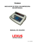
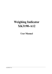
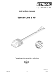
XK3190-A9+
Weighing Indicator
USER’ S MANUAL
X K 3 1 9 0 - A 9+
Content
Chapter One
Technical Parameter…………………………………………………….3
Chapter Two
Installation…………………………………………………………………..5
I.
II.
III.
IV.
V.
Indicator front and back scheme……………………………………….5
Connection between Load cell and Indicator……………………..5
Connection between Printer and Indicator…………………………6
Connection between Scoreboard and Indicator………………….7
Connection between Serial communication interface and
indicator……………………………………………………………………………..9
Chapter Three Operation…………………………………………………………………….12
I.
II.
III.
IV.
V.
VI.
VII.
VIII.
IX.
X.
XI.
XII.
XIII.
Start and Start with Auto-zero……………………………………………12
Manual zero (semi auto zero)…………………………………………….12
Tare
function………………………………………………………………………12
Setting and operation of Date and Time…………………………….13
Battery application…………………………………………………………….13
Inner code
display………………………………………………………………13
Saving for Data
record………………………………………………………..14
Printing
operation………………………………………………………………16
Report
printing…………………………………………………………………..19
Delete of Data
record…………………………………………………………20
How to input memorized TARE weight………………………………20
Power saving…………………………………………………………………….21
Check the software version………………………………………………..21
Chapter Four
Maintenance and Cautions……………………………………………21
Chapter Five
Information Indication…………………………………………………..23
Appendix……………………………………………………………………………………..…………25
DEAR USERS:
PLEASE READ THIS USER’S MANUAL CAREFULLY BEFORE USING
THE INDICATOR
2
X K 3 1 9 0 - A 9+
Chapter One
Technical Parameter
Model
XK3190-A9+
Accuracy
Class III, n=3000
Conversion
Δ-Σ type of A/D
Input signal range
-16 mV~ 18 mV
Conversion speed
10 times/second
A/D resolution code
1 million code
Calibration
All operation made by keys
Excitation power
DC, 5V, able to connect with 8pcs of 350Ω load cells or
16pcs of 700Ωload cells
Load cell connection
method
6 wire method, long wire auto compensation
Display
7 LED digit, 7 status indicating lights, 3 battery
indicating lights.
Display circulation
100ms
Division
1/2/5/10/20/50/100 optional
Clock
Can display year/month/day, hour/minute/second,
auto reap year and moth
Number keys
0~9
Function keys
15 (10 of them are share with number keys for
combine application)
Material for keys
Light touch type of pellicle
Scoreboard connection
interface
Serial output
Transmission method
Current loop/ RS232 signal
Transmission data type
11 bytes
Baud rate
600
Transmission distance
≤30m
Serial communication interface
Transmission method
RS232C/RS422(optional)/ RS485(optional)
Baud rate
Baud rate option 600/1200/2400/4800/9600
3
X K 3 1 9 0 - A 9+
Transmission data format
Transmission distance
Standard parallel output
interface
Built-in printer (for A9+P)
10 bytes: 1 byte is start, 8 data bytes (ASC II code), 1
byte is stop.
RS232:≤30m
RS422/RS485:≤1200m
To connect with TpuP 16 micro printer; wide line
printer like M800、KX-P1121、KX-P1131、LQ300K
+、LQ1600K; POS58, T58D thermal micro printer.
Printing system: dot-matrix (96 dots each line), adopts
M-150 II printing head or TpuP-16B printing head.
Printing paper: standard blank paper, width:
44.5±0.5mm, thickness: 0.07mm, paper roll external
diameter less then 50mm
Life span for Printing head: 0.5×10⁶ lines
Printing ribbon: blue ribbon are installed in the
removable ribbon box, its life span is 1×10⁶ lines
Data saving
AC power
1000 units of truck No. and tare, 201 unit of cargo,
1001 unit of weighing record
AC 220V(-15%~+10%);50Hz(-2%~+2%)
DC power
Adopts 6V/10AH battery (external)
Battery application
About 24h (fully charge without using the built-in
printer)
Battery charging
About 30h
AC fuse
500mA
Application temperature
Storage temperature
0℃ -- 40℃
-25℃ -- 55℃
Relative humidity
≤85%RH
Pre-heat time
15 min
Appearance
310×195×186 (mm)
Weight
About 2.5kg
4
X K 3 1 9 0 - A 9+
Chapter Two
Installation
I. Indicator front and back scheme
(Graph 2-1) Front View
(Graph 2-2) Back View
II. Connection between Load cell and Indicator
1. The 9-pin socket is used for connection with load cell, which foot definition is
5
X K 3 1 9 0 - A 9+
shown in graph 2-3.
2. If 4-core shielded cable is used, +S must be short connected with +E, so did -S and
-E.
3. ▲!Indicator must be reliably connecting to Load cell and shielded-cable of load
cell must be reliably connected to underground. If indicator is powered on,
the user should not plug or unplug in order to protect the indicator and load
cell.
4. ▲!Load cell and indicator are static sensitive devices; you must adopt anti-static
measures. In order to protect the operator, indicator, and relevant devices,
you should install lightning rod in the thunderstorm frequently happening
area
-E
-S
1
2
Shield
3
4
5
6
7
8
9
+E
+S
-IN
+IN
Terminal of Indicator
Terminal of Sensor
+
6 +E
7 +S
Bridge of Power Supply
_
2 -S
1 -E
9 +IN
Signal Output
8 -IN
5 Shield
Graph 2-3: Connection of the load cell
III. Connection between Printer and Indicator
1. The printing interface adopts the standard parallel interface. The 25-pin RS232
socket is illustrated below:
6
X K 3 1 9 0 - A 9+
2. Caution for Printing
▲!Printing function must be set in indicator before using it.
▲!Printer and Indicator’s interface must be connected by professional printer
connection wire. If the connection of each foot is wrong, it will damage indicator’s
output interface or printer’s input interface, or worse will be damage of indicator or
printer.
▲!When you use printer, you must make sure each pin of the interface is correctly
connected, then turn on the indicator, and turn on the printer at last. When you stop
using the printer, you must turn off the printer first, then off the power of indicator,
and then disconnect the wires. If the order is wrong, it may damage the indicator and
printer. Please NOTICE THAT!
▲!Due to the various type of printer exists in the market which has different
function and capability, please use the printer with the model which we recommended.
▲!Printer must connect with GND reliably. Otherwise, it may interfere the normal
function of indicator or damage the indicator and printer.
IV. Connection between Scoreboard and Indicator
▲!Interface of indicator for scoreboard’s and scoreboard’s connection must be
correct, if there is any mistake on that, it will damager the indicator interface and
scoreboard’s input interface, or even worse, the indicator and scoreboard will be
damaged. The wire for connection must be assorted professional connection wire.
1. Scoreboard adopts 15 core RS232 socket (share with serial communication interface),
the definition of foot 9 and 10 is as follow graph (2-5).
7
X K 3 1 9 0 - A 9+
(Graph 2-5 ) serial communication and scoreboard output interface
2. Scoreboard adopts current loop or RS232 by ACII code serial output, baud rate is 600.
Each frame has 11 bytes of data, 1 start bit (0), 8 data bit (lower bit is in the front), 1 stop
bit (1).
3. Every unit of data is send out in every 100ms, each unit of data contains 3 frames data,
its definition is as follow (2-6):
First frame:
(Graph 2-6.1) first frame wave graph
Second frame:
(Graph 2-6.2) second frame wave graph
Third frame:
(Graph 2-6.3 ) third frame wave graph
8
X K 3 1 9 0 - A 9+
First frame data:mark bit is 0
X : D0、D1、D2 – is the location of decimal ( 0~4 )
Y : D3 — is weight symbol ( 1-negative、0-positive )
D4 — back up
G 18~G16: Weight (N.W.) data
Second frame:mark bit is 0
G15~G8: Weight (N.W.) data
Third frame:mark bit is 1
G7~G0 : Weight data
G0~G18:19 digits ACII code of weight (N.W.) consist by the digits from low to high
V. Connection between Serial communication interface and indicator
▲!communication interface output line should connect with computer correctly, if
there is any mistake on that, it will damage indicator output interface or computer
communication input interface or even damage indicator and computer and its
external devices.
▲!For computer communication, it requires knowing computer technology and
programming ability. Unprofessional people, please don’t connect it at your will.
XK3190-A9+ has RS232/RS422 (optional)/RS485 (optional) serial communication
interface, can communicate with computer.
1. Communication interface adopts 15-core RS232 socket (share with scoreboard), its
definition of foot is shown in Graph 2-5 (foot 6.7,8) RS232 or foot 1, 2, 3, 4, 8
(RS422/RS485)
2. All data is of ASCII, every unit of data consist of 10 bytes, first bit is start bit, 10th
bit is stop bit, 8 bit in the middle is data bit, communication method divided as
follow:
(1) Continuous method (Tf=0):
The sending data is the current weight (G.W or N.W). each frame of data
consist of 12 unit of data. Format as follow:
Xth bit
1
02(XON)
2
+ or 3
Weighing data
:
Weighing data
:
Weighing data
8
Weighing data
9
Decimal No.
th
X bit
10
XOR checking
11
XOR checking
12
03(XOFF)
XOR=2⊕3⊕……8⊕9
Content and note
start
symbol bit
high bit
:
:
low bit
from right to left(0~4)
Content and note
4 bit in high bit
4 bit in low bit
end
(2). Order method (tF=1):
9
X K 3 1 9 0 - A 9+
Indicator output corresponding data according to upper monitor’s order. Each
order each frame of data. Upper monitor sending order as follow:
Xth bit
1
2
Content and note
start
address S/N
order A:handclasp
order B:read G.W.
Order C:read TARE
Order D:read N.W
Order E:read truck No.
Order F:read cargo No.
4 bits of high bit
4 bits of high bit
end
02(XON)
A~Z
A~F
3
4
5
6
XOR=2⊕3
XOR checking
XOR checking
03(XOFF)
Indicator output content:
Xth bit
1
02(XON)
2
A~Z
A~F
Content and note
start
address S/N
Order A:handclasp
Order B:send G.W.
Order C:send TARE
3
Order D:send N.W
Order E:send truck No.
Order F:send cargo No.
4
Output corresponding data according to order
Output corresponding data according to order
:
n-1
Output corresponding data according to order
n
Output corresponding data according to order
n+1
XOR checking
4 bits of high bit
n+2
XOR checking
4 bits of low bit
03(XOFF)
n+3
XOR=2⊕3⊕……( n-1 ) ⊕n
Indicator output 4~n data content as follow:
6 units of data for each
Order A No Data
frame
14
units of data for each
Order B G.W,format:
frame
a:
symbol (+ or -)
b:
G.W. ( 6 bits)
:
(from high to low)
g
h: decimal from right to left ( 0~4)
10
X K 3 1 9 0 - A 9+
Order C Tare,format:
a:
symbol (+ or -)
b:
Tare ( 6 bits)
:
(from high to low)
g
h: decimal from right to left ( 0~4)
Order D N.W,format:
a:
symbol (+ or -)
b:
N.W ( 6 bits )
:
(from high to low)
g
h: decimal from right to left ( 0~4)
Order E Truck No.,format:
a:
highest bit of Truck No.
b:
second bit of Truck No.
:
(from high to low)
e:
lowest bit of Truck No.
Order F Cargo No.,format:
a:
highest bit of Cargo No.
b:
second bit of Cargo No.
c:
third bit of Cargo No.
14 units of data for each
frame
14 units of data for each
frame
11 units of data for each
frame
14 units of data for each
frame
Note 1: confirmation of XOR checking 4 bits of High and low: if it is ≤9, then to plus 30h,
and being ASCII to send. For example: if it is 6, plus 30h, then it equals 36h that is 6 in ASC
II code to send out; if it is >9, then plus 37h that will become a letter of ASCII to send
out. For example: it is B, plus 37h equals 42h that is B in ASCII to send out.
3. Upper monitor sending order list (set indicator communication address as 01):
Order type Order definition
Upper monitor sending order (in hex)
Handclasp
02 41 41 30 30 03
A order
B order
Read G.W
02 41 42 30 33 03
C order
Read TARE
02 41 43 30 32 03
D order
Read N.W.
02 41 44 30 35 03
E order
Read N.W.
02 41 45 30 34 03
Read N.W.
F order
02 41 46 30 37 03
4. Setting of indicator communication parameter:
(1). Communication parameter
Communication parameter consists of communication address, baud rate, and
communication method.
(2) Communication parameter setting procedure:
Step
Operation
display
1
Press [Print In weighing mode
setting]
11
Note:
X K 3 1 9 0 - A 9+
2
Press[9][8]
Press[Input]
3
Press[1]
Press[Input]
4
Press [1]
Press [Input]
5
Input[0]
Press[Input]
6
[P
[P
00 ]
98 ]
Input setting password“98”
[ Ad r ** ]
[ Ad r 01]
Communication address ( 01~26 )
For example:1
[bt
*]
[bt
1]
[tF
[tF
*]
0]
Serial communication baud rate
definition of 0~4:
Baud Rate:600、1200、2400、
4800、9600
Serial communication method:
0—continuous method, no receiving
1—order answer method
2—old D2+ continuous communication
method, each frame 8 bits
3--- new D2+ continuous D2+
communication method, each frame
9 bits (Note: 2)
For example:0
Weighing mode End of communication parameter
setting.
Note 2: old D2+ continuous communication method output data in ASCII, each frame with
8 bits (include decimal). Data transmit from low to high, each frame divided by “=”.
Sending data is N.W (the displaying weight on indicator), if current display weight is 70.15,
then indicator continuously sending like this 51.07000=51.07000=51.07000……
Chapter Three Operation
I.
Start and Start with Auto-zero
1. Connect AC or external battery, and turn on the indicator, it will perform
“999999-000000” self checking, then it will enter weighing mode.
2. The self checking can be stopped by pushing any key.
3. While indicator is on, if loading weight on the scale deviates from the zero point, but
still within zero set range, the indicator will set zero automatically. Start Zero range
selecting, setting method, please refer to relative chapters.
While normal operation, the calibration switch should be on the
spot of calibration forbidden (Left).
II.
1.
Manual zero (semi auto zero)
Press [ZERO] key to make indicator zero and the zero indicating light will be on.
12
X K 3 1 9 0 - A 9+
2.
when display weight deviate from ZERO, but in the range of ZERO, [ZERO] key valid,
otherwise [ZERO] will be invalid, the parameter setting and setting method of ZERO
range refers to calibration user’s manual.
3.
III.
Only when STABLE light is on, ZERO is allowed to operate.
Tare function
1. Normal Tare :
When Indicator at weighing status and displaying positive weight stably,
press [Tare] key, indicator will deduct the displayed weight value as tare weight, and now
indicator shows N.W is 0, TARE light is on.
2. Preset tare:
When Indicator at weighing status, press [Pre Tare] key, and indicator will display
[P *****], now indicator shows the original TARE weight. If a new TARE weight needs to
be set, please input it by Numeric keys, press [Input] to confirm it.
3. Call Tare by truck No.
In weighing mode, press [Truck No.] key, indicator will display [o *****], input
correct truck No., then press [Tare], indicator will find the corresponding Tare
weight from the RAM.
In weighing mode, continuous TARE is allowed. When tare weight is zero, TARE indicating
light is off, when indicator matches the condition of ZERO, press [ZERO] to make TARE as
0, TARE light will be off.
IV.
Setting and operation of Date and Time
1. In weighing mode, press [date] to display current date and the date light will be
on. If it is correct, press [input] or [weigh] to exit, if the time is wrong, then input
the right time by numeric keys then press [input] to confirm.
2. In weighing mode, press [time], time light is on and indicator shows current time
and running automatically. If the time is right, press [input] or [weigh] to exit, if it
is wrong, input right time by numeric keys, then press [input] to confirm.
V.
Battery application
1. When only use battery as power, battery indicting light will tell the volume of
battery on the left of display. When battery is full, 3 indicating lights will be on,
when voltage is almost full, the 2 indicating lights will be only, when only 1 light is
on, that means the battery is low. Then you need to charge the battery, when
voltage is around 5.5V, indicator will cut power to protect the battery
automatically.
2. connect battery to indicator, then connect the AC power, indicator will charge the
battery automatically (fully charge need about 30 hours)
3. The battery should be fully charged for first time running.
4. battery connection line marks red socket is positive (+) connects with battery’s
13
X K 3 1 9 0 - A 9+
positive pole, black line is negative (-) is to connect with battery negative pole.
5. if positive and negative pole is connected reversely, it will make fuse broken to
protect the battery. Now, connect two poles correctly, and restart the indicator,
it will work normally again.
Battery is consuming products, not in the range of guarantee.
VI.
Inner code display
1. In weighing mode, press [print set], then input [2], [8], indicator will enter into
inner code display mode, and inner code light is ON. Press [print set], input [2], [8],
indicator will exit inner code display mode; inner code light will be off.
2. In inner code display mode, only [ZERO], [Print set] key is available, other keys are
all unavailable.
3. 20 inner code equals 1 division, E.g. while n=3000, the full scale’s inner code is
60000 code.
VII. Saving for Data record
1. Indicator regulates that truck No. should be 5 digits, cargo No. is 3 digits. The
maximum storage is 1000pcs of truck No., 201pcs of cargo No.
2. Every complete unit of weighing record is stored; indicator will print out this unit
of data. (if printing setting is valid)
3. Data storage has follow 3 methods:
(1) Store empty truck, then full truck store; or store full truck store then empty
truck store. That is to say, twice storage consists of a complete unit of record.
(2) Full truck for weighing and TARE has been obtained, one time storage will
form a unit of complete record.
(3) The weight object is a kind of cargo, not a truck, then one time storage will
form a unit of complete record for always.
In order to automatically recognize the above three types of storage, XK3190-A9+
makes following special agreement.
▲!Truck No. must be any number from 00001~99999, that is
00000 can not be a
real truck number. If truck No. has been set as 00000, that means it is not a truck but a
14
X K 3 1 9 0 - A 9+
cargo.
▲!Cargo No. must be any number from 000~200.
▲!If the TARE light is on, that means TARE weight is obtained, so one time
storage will form a complete record.
▲!If the truck No. has been set as any 5-digit number over the range of 00000,
and the TARE light is OFF (G.W weighing mode), then twice storage will form a
complete unit of record.
4. Storage operation method
Step
(Table 3-1)
Operation
Display
Note
1
Press [Print]
In weighing mode
2
Press numeric keys
[ o *****]
Input Truck No.
to input truck No.
[ o 03217]
E.g.: 03217
Press [Input]
3
4
Input cargo No.
[hn
***]
Press [input]
[hn
035]
Input cargo No.
E.g.: 35
Press [10]
[BFL **]
Input percentage
Press [input]
[BFL 10]
of deduction
ratio
E.g. 10
End of storage
Indicator’s data storage can be set as truck No. type or non truck No. type, see
chapter of Printing. If set non truck No. type, all operation or printing content related
to truck No. will not be existed. Also, indicator’s data storage can be set according to
cargo No. or non cargo No. details see Chapter of printing setting.
▲! When Data is not stable or G.W. ≤0 or N.W. ≤0, the data can not be saved.
5. About auto storage or printing.
(1) auto storage printing setting refers to printing setting chapter
(2) auto storage of printing does not contains for twice storage method
15
X K 3 1 9 0 - A 9+
(3) Stored truck No. and cargo No is the truck No. and cargo No. which has been
stored before.
(4) Auto storage TARE can be divided as follow three types:
1).when TARE light is on, current TARE weight will be saved to this unit of
record.
2).when TARE light is off, indicator will find TARE weight under this truck, and
take this TARE weight to save in this unit of data.
3).when TARE light is off, and there is no such TARE in RAM, then it will save
0 as TARE weight to this unit of record.
6. If truck No. is over 1000, indicator will show [Err 10], then you can refer to
Chapter 7 to clear one truck No. or all truck No.
VIII. Printing operation
1. Printing set (Table 3-2)
Step
Operation
Display
Note
1
Press [print set]
[P 00]
Input 97
Press [9] [7]
[P 97]
Press [Input]
2
Press [1]
[Auto *]
Press [Input]
[Auto 1]
Selecting Auto/Manual Printing
0- Manual
1- Auto
3
Press [3]
Auto indicating
Selecting printer:
Press [Input]
light is on
0-invalid printing
[Type *]
1-TPup16 micro-printer[English ]
[Type 3]
2-TM800 printer
3-Panasonic KX-P1121 Printer
4-Epson CQ-1600K,
LQ-300K+,Panasonic KX1131
5-Built-in micro-printer (only for
A9+P)
6-External thermal printer POS58,
T58D etc.
16
X K 3 1 9 0 - A 9+
4
Press [5] [0]
Press [Input]
[HL **]
Selecting Printing Restriction
[HL 50]
00-print only when display
returns zero
25-print only when display <25%
F.S.
50- Print only when display <50%
F.S.
75- Print only when display <75%
F.S.
99 Print even when it is at F.S.
5
Press [3]
[Arr *]
Selecting Printing format:
Press [Input]
[Arr 3]
Arr=0: record format
1: 1-page format
2: 2-page format
3: 3-page format
6
Press [1] [0] [0]
[L *****]
Setting the minimum auto
[L001.00]
printing weight, L must be larger
than 10 divisions.
E.g. 1.00
7
8
Press [0] [5]
[b
**]
Setting paper rolling lines (0~30)
Press [Input]
[b
05]
E.g. :05
Press [1]
[Ode *]
Selecting blank- filling print
Press [Input]
[Ode *]
format:
0-blank-filling print not selected
1-blank filling print selected
2-apply horizontal page print
9
Press [1]
[Dct
*]
Selecting the deduction rate at
Press [Input]
[Dct
1]
blank-filling print form:
0-deduction invalid
1-deduction valid
10
Press [0] [1] [1]
[Y ***]
Y’s definition refers not Note 4.
Press [Input]
[Y 00011]
(non “0” number will be all
considered as “1”)
11
Press [8]
[teln
*]
Select Tel. No digits (0~8)
Press [Input]
[teln
8]
0: no print Tel. No.
1~8: print Tel. No. in continuous
17
X K 3 1 9 0 - A 9+
sheet form.
12
13
Press [5] [8] [8] [6]
[tH ****]
High 4 bits of Tel. setting
Press [Input]
[tH 5886]
E.g. 5886
Press [0] [0] [0] [3]
[tl
****]
Low 4 bits of Tel. setting
Press [Input]
[tl
0003]
E.g. 0003
End of operation
Note1:
(1)
when you use A9+P’s built-printer, the parameter of Printer type
must be selected “5” to ensure the normal work.
(2)
Step 8 and 9 only valid for Printer model 2.3.4, invalid for other
model.
(3)
Tel. No. only can print out when built-in printer is applied, and it
is printed at bottom of the weighing bill. Therefore, step 11, 12,
13 is only for printer model is 5 (these steps will be invalid when
you select other models.)
① Tel numbers are 7 digits, then tH input 3 digits, and tl input 4 digits.
② Tel numbers are 3 digits, then tl input 3 digits, step 12 will be
skipped.
③ Tel numbers are 0 digits, and then step 12 and 13 are skipped.
Note 2:
Y parameter has 5 digits, from left to right is 1—5, each digit’s definition is as follow:
1st: 0 twice weighing printing mode,
1
once weighing printing mode.
2nd: 0 invalid power saving,
1
valid power saving
3rd: 0 Kg as weighing unit,
1
T as weighing unit
4th: 0 weighing record has no cargo NO., 1
weighing record has cargo No.
5th: 0 weighing record has no truck NO., 1
weighing record has truck No.
Note 3:
1. Only when filling printing type selected, deduction ratio can be
applied.
18
X K 3 1 9 0 - A 9+
★ Printing format refers to appendix
★ Filling printing type can use specialized non-carbon copy and printing paper to
fast print in triplicate. Or specialized normal printing paper to fast print in one
copy.
★ Users may need specialized format of filling printing, please contact Dealers.
2. Indicator’s data storage and printing is simultaneous, use [print] key store a unit
of complete data, meanwhile, it is printed out. (if printing setting is valid.)
3. if there is any reason like printer false which leads incomplete printing, after false
is gone, press [supply print] to supplement print the current saved data.
4. after a series of weighing is done, press [accu print] to print the accumulative
weighing result of this group of record.
5. when twice printing mode is set, use empty to loaded truck or loaded to empty
truck, after first storage, indicator only shows [LoAd ] about 1.5 seconds to hint
the operator without any printing, because this group of data is incomplete.
But, if you print [supply print] can still print out this incomplete data.
Print result will be always: ① serial number is blank.
② G.W and N.W. is 0
③ Tare weight is current displayed weight.
(Twice printing mode’s setting; please refer to Y parameter of printing setting.)
6. When one time weighing mode is applied, each weighing will be considered as a
complete record to store and print. If the indicator is in the TARE mode, then
current TARE weight will be considered as record TARE weight. If indicator is not
in TARE mode, then it will call the corresponding TARE weight of such truck No. as
recorded TARE weight (if there is not memorized TARE weight, then this record’s
TARE weight will be 0). One time printing mode setting refers to Y parameter of
printing setting.
7. When built-in printer is applied (printer model=5) and it is in the weighing mode,
[weighing] key will be performs as paper rolling.
19
X K 3 1 9 0 - A 9+
IX.
Report printing
1. Press [print set], then press [1], press [input] to print sorted statistic daily report
of current date. (That is current date’s statistic report by time order, report by
truck No., report by cargo No.). if you want to print previous daily report, please
change system’s data to the day you need, then followed the above steps to print
it. After printing and change the date back to current data.
2. Press [print setting], press [2], press [input] to printer report 1 (by time order)
3. Press [print setting], press [3], press [input] to printer report 2 (by truck No.)
4. Press [print setting], press [4], press [input] to printer report 3 (by cargo No.)
5. Press [print setting], press [5], press [input] to printer report 4 ( all truck No. and
its memorized TARE weight statistic report.)
X.
Delete of Data record
1. this indicator allows methods of deleting data as follow:
① Delete all record. (Include all truck No. and memorized tare weight.)
② Delete one truck No., this truck No.’s memorized TARE weight and
corresponding weighing results.
2. When use any method to delete record, indicator will show [Sure 0], please
choose YES or NO to confirm. When [sure]= not O, press [input] to confirm. If you
want to deny it, let [Sure]=0, then press [input] or [weigh] to exit.
3. operation method:
(1) [Method ①]: in weighing mode and calibration switch is on the forbidden
spot (left side), press [Func] to delete all weighing record.
(2) [method ②]: in weighing mode, press [truck No.], and input one truck No.
then press [ZERO] can delete this truck number and its corresponding
memorized TARE weight and corresponding record.
▲ !Data can’t be recovered after delete. Be Cautious on this operation to prevent
20
X K 3 1 9 0 - A 9+
lost of DATA.
▲
XI.
!After calibration or amend printing parameter, please delete all weighing record.
How to input memorized TARE weight
Indicator and memorize 1000 TARE weights, input method are as follow:
1. Input TARE weight with numeric keys.(*:is original setting value)
Step Operation
Display
Note:
1
Press [truck
In weighing mode
NO.]
2
[o *****]
Input truck No
E.g. :35790
Input truck
[o 35790]
No.
Press [input]
3
[P *****]
Input Tare weight E.g: 1000(kg)
Input Tare
[P 01000]
weight
Press [input]
4
Back to weighing mode End
2. weighing mode to store TARE weight
In TARE weight display mode, drive empty truck on platform, when scale is stable,
press [store TARE] key, then input truck No. and press [input].
3. when each group of weighing record is store, if there is no memorized TARE
weight of this truck No., then TARE weight of this group of weighing record will be
considered as this truck’s memorized TARE weight and store to RAM.
XII.
Power saving
When power saving function is set to valid, indicator will come to power save mode
after the scale is on ZERO point (no TARE has been done) for 30 seconds. (LED display will
be off, and keep status indicating light.) Now, you can press any key can wake indicator
up.
Power saving function’s setting; please refer to Y parameter of printing setting.
XIII. Check the software version
In weighing mode, press [print set] and input password [30] and then press [input],
indicator will show [Ver *.**]. *.** is the version of this indicator’s software. Press [weigh]
to go back to weighing mode.
21
X K 3 1 9 0 - A 9+
Chapter Four
1.
2.
3.
4.
5.
6.
7.
Maintenance and Cautions
To guarantee the clarity and using life, the indicator shouldn’t be placed directly under
sunshine and should be placed in the flat place.
The indicator should avoid dust pollution, vibration and moisture.
Load cell should connect with indicator reliably, and the system should be connected into
ground properly. The indicator must be kept away from high electrical and magnetic field,
high corrosion, flammable and explosive objects.
▲ !Do not apply this indicator to the environment with flammable gas or steam,
and the indicator can not be applied in the system with pressure tank.
▲ !In the area where thunder is frequent happen, it must install anti-thunder
devices to ensure operator’s safety and prevent indicator and other device will
be damaged by thunder.
▲ !Load cell and indicator are static sensitive devices; you must adopt static free
measure. Strictly forbid welding or other super electric field operation on the
platform. In the thunder storm season, it must be installed with reliable
anti-thunder device to prevent any damage to load cell and indicator from
thunder and ensure operator’s safety and weighing device or other related
device’s safe operation.
It is strictly forbidden to clean the case of indicator with intensive solvents (for example:
benzene and nitro oils)
Liquid and electrical conducting particles should not be poured into the indicator, otherwise
the electronic components will be damaged and electric shock is likely to happen.
You should cut off power supply of indicator and relevant device before you pull-in and out
the connecting line of indicator and external device.
▲ !You must cut off power supply of the indicator, before you plug the
connecting line of the load cell in and out.
▲ !You must cut off power supply of the indicator and the printer, before you
plug in connecting line of the printer.
▲ !You must cut off power supply of the indicator and the scoreboard, before
you plug connecting line of the scoreboard in and out.
▲ !You must cut off power supply of the indicator and the master computer,
before you pull connecting line of communication in and out.
▲ !You must cut off power supply of the indicator and upper monitor, before you
pull connecting line of control output in and out.
Company kindly notice: before using our indicator, please check and inspect the
indicator. Our company only be responsible to the quality of indicator itself, the
maximum compensation of indicator’s malfunction will not be over 2 times of indicator’s
own value. We are not responsible for the problem of the system where indicator is
applied.
22
X K 3 1 9 0 - A 9+
8.
Indicator’s external interface must be used strictly according the our user’s manual. Random
changing of the connection is forbidden. During the using of this indicator, if any problem
happened, please unplug the power plug and send back to factory for repair. Unprofessional
weighing products manufacturer is not allowed to repair it by them to prevent from more
damage and loss. THIS INDICATOR IS NOT ALLOWED TO OPEN IT AT RANDOM,
OTHERWISE NO GURANTEE WILL BE ENSURING.
9. Battery is a consuming product, not in the range of guarantee.
▲ !in order to extend the life span of battery, please use it after fully charged. In
a long time not using the battery, please charge is in every 2 moths, each time
for 20 hours charging.
▲ ! in transportation or installation, it must be handled with care and light
operation, avoid any fierce vibration, concussion, hit to prevent inner
electronic circuit’s short connection and damage of battery.
10. Built-in printer head and printing ribbon is consuming product, not in the range of
guarantee.
▲ !Forbidden to use built-in printer in the environment of dust
▲ !Please don’t use built-in printer while battery is charge.
▲ !While printing, please don’t pull out the paper to prevent damage to printing
head.
▲ ! Please keep dry and clean of the printing head to extend the life span.
11. In condition of normal operation, indicator will be guaranteed in one year since the day
of purchasing. Non-manual malfunction is in the range of guarantee, please send goods
together with guarantee card (S/N must be corresponding) back to supplier for repair.
Manufacturer provides lifelong maintenance of the indicator.
Chapter Five
Information Indication
I. Normal information
1
------
2
Prnt
Wait a moment, inner operating, don’t make any operation.
Wait a moment, the data are being transmitted between indicator
and printer.
3
LoAd
Data is storing.
II. Error information indicating
1 Err
03
Overload warning, unload part of all loading weights.
2 Err
19
Zero or Negative weight value, can’t be printed.
3 Err
11
dissatisfying demands of document format , or printing set is wrong.
Please make new setting.
4 Err
12
dissatisfying demands of the printer set. Printer selection or setting is
wrong, please select and change the printer.
23
X K 3 1 9 0 - A 9+
5 Err
16
Date or Time is illegal, please input right time and date.
6 Err
09
This truck No does not exist.
7 Err
10
The truck No. stored exceeds 1000.
8 Err
28
printing date is smaller than stored weighing record’s date. Please
delete the larger date record or revise current date and let it not smaller than stored
weighing record’s date.
III. Wrong connection information indicating
1 Err
P
It means the printer has trouble or wrongly connected. Press any key to
quit. Reconnect the printer or change the printer.
2 Err
01
It means the load cell signal line is wrongly connected, or its signal is
negative or exceeds the range our indicator’s input signal.
(1) If this scale is in working (previous working good), then can judge that the
wire connection is malfunction or load cell is damaged.
(2) If this scale hasn’t been calibrated, the user should check the load cell’s
connection wires is correctly connected or load is working properly.
3.
Err
02
It means the load cell’s wires are wrongly connected, or the signal value
exceeds the A/D converting range.
(1) If this scale is in working (previous working good), then can judge that the
wire connection is malfunction or load cell is damaged.
(2) If this scale hasn’t been calibrated, please check as following:
a) Check the load cell’s connection wires is right or not carefully.
b) Check if load cell is suitable or not: It should satisfy the following terms:
The load cell’s empty scale loading capacity+ scale’s capacity<load cell’s
capacity.
4. Err
05 : AD works in false.
1) If 4-pin shielded cable is applied, please check if you had
short-connected the +E and +S, -E and -S.
2) Please check if the connection of load cell is correct.
IV. Error of components and solving method
1 Err
18
Key board has problems, It will indicates for ten seconds, then
indicator enters weighing mode. Change the keypad.
2 Err
20
The data is partly lost in RAM. Operator should switch the calibration on
and restart the indicator to self-check. If there is no Err 20, then switch the calibration off.
3 Err
21
Calibrating data have been lost in RAM and EPROM, Operator must plug
24
X K 3 1 9 0 - A 9+
in the calibration plug, then re-input the original calibration data, turn
on the indicator again or re-calibrate it.
4 Err
22
RAM has been damaged, change the chips and re-calibration.
5 Err
23
EPROM has been damaged, change the chips and re-input the original
data, re-start the indicator or re-calibration.
6 Err
SP
built-in printer is malfunction, press any key to exit. Exam inner
printer connection wire or change the printing head and driver board.
APPENDIX
Appendix I.
Erect bill format:
Weighing bill
S/N
0001
Date
2008-01-01
Time
12.02.31
Truck.No
12345
C. No.
022
G.W.
2.000(kg)
TARE
0.300(kg)
N.W.
1.700(kg)
Horizontal bill format:
S/N
Date
0001 2008-01-01
Record format:
S/N
0002
0003
0004
Total:
Time
12.03.24
12.03.24
12.04.11
Weighing bill
S/N
0001
Date
2008-01-01
Time
12.02.31
Truck.No
12345
C. No.
022
G.W.
2.000(kg)
TARE
0.300(kg)
N.W.
1.700(kg)
Time
12.03.24
Weighing
bill
Truck.
Cargo. No.
12345
033
Weighing
Truck No.
Cargo
12345
033
00888
033
00888
022
G.W:8.000(kg)
S/N
Date
Time
Truck.No
C. No.
G.W.
TARE
N.W.
G.W
2.00
Weighing bill
0001
2008-01-01
12.02.31
12345
022
2.000(kg)
0.300(kg)
1.700(kg)
TARE(kg)
0.300
N.W (kg)
1.700
bill
date:2008-01-01
G.W. (Kg)
TARE (Kg)
N.W. (Kg)
2.000
0.300
1.700
2.000
0.300
1.700
2.000
0.300
1.700
N.W.:6.800(kg)
Filling type format:(printing only needs 5 seconds.)
过 磅 单
WEIGHT
第 1 联司磅员留存
序号 SERIAL No.
日期 DATE
时间 TIME
车号 VEHICLE No.
货号 CARGO No.
总重 GROSS
皮重 TARE
扣率 DISCOUNT
25
BILL
Operator
123
2008-01-01
12 .35 .28
1580
80
10
kg
kg
%
X K 3 1 9 0 - A 9+
1350
净重 NET
备 注
REMARK
kg
Appendix 2: report format example(applicable for printer type=2, 3)
Daily report 1
Date:2008-01-01
S/N
Time
Truck No.
Cargo
G.W.(kg)
TARE (kg)
N.W.(kg)
0002
12.03.24
12345
033
2.000
0.300
1.700
0003
12.03.24
00888
033
2.000
0.300
1.700
0004
12.04.11
00888
022
2.000
0.300
1.700
Total:
G.W.:8.000(kg)
N.W.:6.800(kg)
Daily report 2
Date:2008-01-01
S/N
Truck No.
Truck weight
Times Total weight(kg) Total N. W. (kg)
(kg)
0001
12345
0.300
0002
4.000
3.400
0002
00888
0.300
0002
4.000
3.400
Daily report 3
Date:2008-01-01
S/N
Cargo No.
Times
Total N. W. (kg)
0001
022
0002
3.400
0002
033
0002
3.400
Appendix 3:Micro printer format(Applicable for printer type=5)
Folding format:
S/N
0001
DATE 02-03-14
TIME 10 . 57 . 27
T.No.
00001
C.No.
001
G.W.
10 . 00kg
TARE
1 . 00kg
N.W
9 . 00kg
tel:1 2 3 4 5 6 7 8
T.G.W:
10 . 00kg
T.N.W:
9 . 00kg
26
X K 3 1 9 0 - A 9+
Record format:
DATE 02-03-14
S/N
weight kg
0001
9 . 00
0002
9 . 00
TOTAL:
18 . 00kg
Appendix 4:Printing operation examples
I. One time manually pre-set TARE printing weighing bill
Step
1
2
Condition
Goods on
platform
Input
pre-set
TARE weight
Operation
Press
[preset
TARE]
E.g.[1000]
Display
[P00.000]
[ *****]
[o *****]
[o 00123]
[hn
[hn
3
4
5
Input truck No.
Press [input]
Press [print]
E.g. [00123]
6
7
Input cargo No.
Press [input]
E.g.[ 11 ]
8
Note:
[P1. 000]
Press [input]
***]
011]
[ Prnt
]
Minus TARE weight
Original truck No.
If needs original truck No.
press [input] directly, no
need to change.
Original cargo No.
If needs original cargo
No. press [input] directly,
no need to change.
Print weighing bill
II. One time manually print cargo weighing bill directly.
Step
1
2
Condition
Goods on
platform
Input“0”
Operation
Press [print]
Display
[o *****]
E.g.[ 0 ]
[o 00000]
Note:
Original truck No.
“0” truck No. means the
weighing object is cargo.
3
Press [input]
[hn ***] Original cargo No.
4
Input cargo No.
E.g.[ 11 ]
[hn 011] If needs original cargo No.
press [input] directly, no
need to change.
5
Press [input]
[ Prnt ]
Print weighing bill
III. Print weighing bill (twice weighing storing method,that is empty and loaded truck or
loaded and empty truck)
Step
1
Condition
Empty truck on
platform
(wait for
stable light is
Operation
Press [print]
Display
[o *****]
27
Note:
Original truck No.
X K 3 1 9 0 - A 9+
2
on)
Input new truck
No.
E.g.[00123]
[o 00123]
3
4
Press [input]
input new cargo E.g. [ 11 ]
No.
5
Press [input]
[ LoAd
Press [print]
[o 00123]
6
loaded truck on
the
platform(wait
for stable light
is on)
[hn
[hn
***]
011]
]
If needs original truck No.
press [input] directly, no
need to change.
Original cargo No.
If needs original cargo No.
press [input] directly, no
need to change.
Back to weighing mode in
1.5 seconds.
Truck No. of step 2.
7
8
Press [input]
[ hn 011 ] Cargo No. of step 3.
Press [input]
[ Prnt
]
print weighing result.
★ Note 5: if the first step is loaded truck, then step 6 should be empty, other
operation is the same.
IV. Pre-set TARE weight and auto printing weighing bill
Step Condition
Operation
Display
note
1
Press [print set]
[Auto *]
Select 1 auto printing
2
Press [1]
[Auto 1]
3
Press [input]
[type *]
Following no need to
amend
4
Press [weigh]
[
0]
Back to weighing mode
5
Press [preset
[P ***]
TARE]
6
Set preset
Input E.g.[100]
[P 00100]
TARE
7
Press [input]
[ -100]
8
Loaded truck
[ 400]
Loaded truck 500, minus
on the
TARE weight 100
platform
9
[Prnt ]
Auto print weighing bill
V. Printing weighing bill by calling TARE weight according to truck No.
step
1
2
3
condition
Truck No. Tare weight has
been preset
Loaded truck on platform
press
(wait for stable light is on) [truck No.]
Input needed truck No.
E.g. [00123]
press
28
display
Note
Has been store in Indicator
[o *****] Original truck No.
[o 00123] If the original truck No. is
corresponding, press [tare]
directly, no need of
inputting truck No.
[ *** ] Minus stored TARE weigh
X K 3 1 9 0 - A 9+
Input new cargo No.
[tare]
press
[print]
press
[input]
E.g.[ 11 ]
Truck leave scale, indicator
shows negative weight
press
[input]
press
[tare]
4
5
6
7
8
[o *****] Needed truck No.
[hn ***] Original cargo No.
[hn 011] If the original cargo No. is
corresponding, press [tare]
directly, no need of
inputting cargo No.
[ Prnt ] Printing weighing bill
[
0]
\back to weighing mode.
VI. set various truck preset TARE weight and manually print weighing bill
step
condition
display
Note
1
press
[o *****] Original truck No.
[truck No.]
2
Input new truck NO.
[o 00123] If original truck No. is
如[00123]
needed, press [input]
directly, no need to input
new truck No.
3
press
[P *****] Preset tare weight
[input]
4
Input preset tare weight
E.g.[100]
[P
100]
5
press
[
000] Back to weighing mode.
[input]
Store various truck’s preset ……
[ …… ]
Set various truck’s preset
TARE weight
TARE weight.
step1-5
6
Loaded truck is on
press
[o *****] Original truck No.
platform(wait for stable
[truck No.]
light is on)
7
Input new truck No.
E.g.
[o 00123] If the original truck No. is
[00123]
corresponding, press
[tare] directly, no need of
inputting truck No.
8
press
[
***] Minus stored TARE
[tare]
weight
9
press
[o *****] Needed truck No.
[print]
10
press
[hn
Original cargo No.
11 Input new cargo No.
[hn
If the original cargo No. is
如[ 11 ]
011]
corresponding, press
[tare] directly, no need of
inputting cargo No.
12
press
[ Prnt ] Printing weighing bill
[input]
13 Truck leave scale, indicator press
[
0]
Back to weighing mode
29
X K 3 1 9 0 - A 9+
shows negative number
[tare]
VII. Printing weighing bill (one time stored type)
step
1
2
Condition
Loaded truck is
on platform
(wait for
stable light
is on)
Input new truck
No.
operation
press [print]
display
[o *****]
Note
Original truck No.
E.g. [00123]
[o 00123]
If original truck No. is
needed, press [input],no
need of input new truck
No.
Original cargo No.
If original cargo No. is
needed, press [input],no
need of input new cargo
No.
Printing weighing bill
3
4
press [input]
Input new cargo 如[ 11 ]
No.
5
press [input]
[hn
[hn
[ Prnt
***]
011]
]
VIII. Daily repot printing (triplicate)
step
operation
display
Note
1
Press [printing
[ P 00]
printing selection
2
Press [1]
[ P 01]
3
press [input]
[ Prnt ] Print out 3 copies of daily report
Note 6:the date of printed daily report is current date of indicator.
(press [date] to check and modify)
IX. General report printing
step
operation
1
Press [print set]
2
Press [2]
3
press [input]
display
[ P 00]
[ P 02]
[ Prnt
]
Note
Printing selection
02 print general report 1;
03 print general report 2;
04 print general report 3;
05 print general report 4。
Print out general report
30