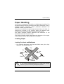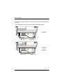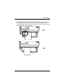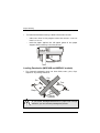
1
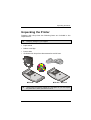
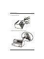
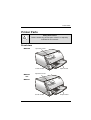
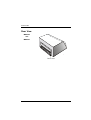
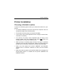
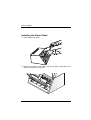
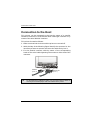
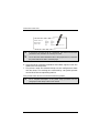
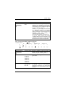
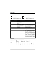
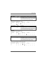
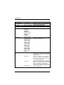
MDP40B
MDP40C
MDP40T
User Manual
Compuprint Information
Thanks for choosing this printer.
Your printer is a reliable working equipment that will be very useful in your
daily job.
Our printers have been designed to be compact and respectful of the work
environment. They offer a wide range of features and multiple functions that
confirm the high technological level reached by the Compuprint S.p.A .
To maintain these printing performances unchanged in the long run,
Compuprint has developed specific consumable accessories for each printer
type (for example: ribbon cartridges for dot matrix printers, toner and OPC
cartridges for laser printers, bubble ink jet cartridges for inkjet printers) that
assure an excellent operation with high printing quality level reliability.
Compuprint recommends to use only its original consumables with
original packaging (identified by its holographic label). In this way, a
proper use of the printer at quality level stated in the product characteristics
can be assured. All typical usage problems related to not certified consumables
may be avoided, such as an overall quality print level degradation and, often,
the reduction of the product life due to the fact that the proper working
conditions for the print heads, OPC cartridge and other printer parts are not
assured.
Moreover, Compuprint does not only certify its consumables in terms of
working conditions but also carefully controls their compliance with the
international standard rules concerning:
•
no cancerous materials;
•
no inflammability of the plastic materials;
•
other standards
Compuprint advices the customers not to use products for which the
compliance to this safety rules are not warranted.
Finally seek your dealer or contact a Compuprint office and be sure that are
provided you the original Compuprint consumables.
A78408356-003
i
FCC Notes
FCC Notes
This equipment has been tested and found to comply with the limits for a Class B
digital device, pursuant to Part 15 of the FCC Rules. These limits are designed to
provide reasonable protection against harmful interference when the equipment
is operated in a commercial environment. This equipment generates, uses and
can radiate radio frequency energy and, if not installed and used in accordance
with the instruction manual, may cause harmful interference to radio
communications. However, there is no guarantee that interference will not
occurin a particular installation. If this equipment does cause harmful
interference to radio or television reception, which can be determined by turning
the equipment off and on, the user is encouraged to try to correct the interference
by one or more of the following measures:
•
•
•
•
Reorient or relocate the receiving antenna.
Increase the separation between the equipment and the receiver.
Connect the equipment into an outlet on a circuit different from that
to which the receiver is connected
Consult the dealer or an experienced radio/TV technician for help.
A shielded Centronics IEEE1284 compliant bi-directional parallel cable,
maximum length 3 meters (10 feet), and a shielded RS-232 serial cable,
maximum length 15 meters (50 feet), are necessary for this device to meet the
requirements of a Class B digital device pursuant to part 15 of the FCC rules.
The above specified cables are readily available as Personal Computer or
Peripheral accessories from multiple retail outlets. Please consult your
dealer for details concerning such cables and also for information about FCC
rules for digital devices.
Changes or modifications to the device covered by this manual, which are not
expressly approved by the party responsible for compliance, could void the
user’s authority under the FCC rules to operate the equipment.
Canadian D.O.C. Radio Interference Regulation
This digital apparatus complies with the Canadian ICES-003 Class B limits
for radio frequency emissions.
Cet appareil numérique est conforme aux limites de Class B de la norme NMB003 du Canada.
EEC Regulations
This equipment conforms to the EEC Directive 89/392 (the sound pressure,
measured according to ISO 7779, does not exceed 70 dBA).
ii
A78408356-003
Table of Contents
Table of Contents
Compuprint Information ..........................................................................ii
FCC Notes ................................................................................................iii
Canadian D.O.C. Radio Interference Regulation ..............................ii
EEC Regulations..................................................................................ii
Table of Contents...................................................................................iiii
Printers Presentation ..............................................................................1
1
Unpacking the Printer .............................................................................3
3
Printer Parts.............................................................................................5
5
Front view ............................................................................................ 5
Rear View ............................................................................................. 6
Printer Installation...................................................................................7
7
Choosing a Suitable Location.............................................................. 7
Installing the Paper Stand .................................................................. 8
Installing the Power Cable................................................................ 10
Installing the Ribbon Cartridge ........................................................ 11
Paper Handling ......................................................................................1
13
Loading Paper .................................................................................... 13
Loading Cut sheet and Multiparts................................................ 13
Loading Passbooks (MDP40B and MDP40C models) .................. 16
Loading fanfold paper (MDP40C and MDP40T models) ............. 18
The Operator Panel ...............................................................................2
22
Function keys ..................................................................................... 22
Leds..................................................................................................... 24
Software Driver Selection ....................................................................2
25
Connection to the Host ........................................................................2
26
Setting the Interface Parameters ..................................................... 27
Parallel Interface............................................................................ 27
Serial Interface............................................................................... 27
A78408356-003
iii
Table of Contents
Printing a Test Page .............................................................................2
29
Printer Setup..........................................................................................3
33
Printing the Printer Setup Forms .................................................... 33
Filling in the Printer Setup Forms ................................................... 36
Reading the Preprinted Forms ......................................................... 36
Printer Setup Flow Chart.................................................................. 37
MDP40 B Model ............................................................................. 37
MDP40 T and MDP40 C Model ..................................................... 38
Setup Parameters .............................................................................. 39
Offset Adjustments ............................................................................ 47
Troubleshooting....................................................................................5
50
Clearing Paper Jams ......................................................................... 50
Print Quality Problems...................................................................... 52
Hexadecimal Dump ........................................................................... 52
Paper Specifications .............................................................................5
53
Cut Sheets .......................................................................................... 54
Fanfold................................................................................................ 55
Passbooks ........................................................................................... 56
Passbooks with Horizontal Fold .................................................... 57
Passbook with Vertical Fold .......................................................... 59
iv
A78408356-003
Printers Presentation
These dot-matrix printers are multi-purpose printers for counter
applications. Their compact structure is designed to be integrated in
an ergonomic environment. These printers provide a high level of
reliability, form-handling accuracy and data integrity. Their main
features are:
• Printing on a wide range of paper media:
- different types of cut sheets, multiparts and passbooks for the
MDP40B model,
-
different types of cut sheets, multiparts and fanfold paper for
the MDP40T model,
-
different types of cut sheets, multiparts, passbooks and fanfold
paper for the MDP40C model,
• High print pressure for multipart documents
• High print quality supplied by a 24 wire print head
• High reliability paper handling
The straight paper path allows the printing on particular
documents such as multipart forms and passbooks (only MDP40B
and MDP40C models).
• Automatic paper thickness adjustment
The print head detects automatically the paper thickness for
correct printing on any type of document.
The MDP40B and the MDP40C models can print also on
documents with a variable thickness, such as passbooks.
• Easy paper handling
The cut sheets are placed on the front table by the operator and
the printer loads it without any other user intervention. The paper
ejection towards the front or the rear of the printer allows an easy
access to the printed document.
For the fanfold paper in the MDP40T and MDP40C models the
printer offers the tear-off feature to tear off the paper exactly at
the paper perforation and the paper parking feature.
A78408356-003
1
Printers Presentation
• Automatic switching between cut sheets and fanfold paper
If the paper path is empty (i.e. the fanfold paper is in the first line
position), when inserting a cut sheet into the printer, it is
automatically loaded after the printer automatically parked the
fanfold paper. The fanfold paper can then be loaded again simply
pressing the LOAD/PARK key.
• Automatic document alignment feature
The printer checks automatically the alignment of the top margin
and the left margin of the document and adjusts it, if necessary.
The printout is therefore performed correctly independently from
the paper loading position.
• Storage of complete configurations (two for the MDP40B
model and four for the MDP40T and MDP40C models) for instant
recall
• Standard parallel and serial interface and automatic switchover function.
• Easy printer setup
• Supported emulations: IBM Proprinter XL24E, XL24E AGM,
2390 and Epson 570
2
A78408356-003
Unpacking the Printer
Unpacking the Printer
Together with the printer the following items are included in the
shipment box:
Notify any damage to your supplier.
• Paper stand
• Ribbon cartridge
• Power cable
• CD-ROM with the printer documentation and drivers.
M DP40B
M DP40C - M DP40T
Always keep the packing material in a safe place as you must repack
the printer into it, when you need to move it.
A78408356-003
3
Unpacking the Printer
1. Open the printer cover.
2. Remove the protection from the print head.
4
A78408356-003
Printer Parts
Printer Parts
Safety Instructions
Never remove any printer part unless it is expressly
indicated in this manual.
Front view
MDP40B
O p erato r P a ne l
P rin ter C o ver
MDP40C
P ap er S tan d
O p erator P a ne l
and
MDP40T
P rin ter C o ver
A78408356-003
P ap er S tand
5
Printer Parts
Rear View
MDP40C
and
MDP40T
R ear cover
6
A78408356-003
Printer Installation
Printer Installation
Choosing a Suitable Location
Consider the following points when you choose the location for your
printer:
• The distance between the printer and the host computer must not
exceed the length of the interface cable;
• The location must be sturdy, horizontal and stable;
• Your printer must not be exposed to direct sunlight, extreme heat,
cold, dust or humidity;
• You need an AC power outlet compatible with the plug of the
printer’s power cord. The voltage of the outlet must match the
voltage shown on the printer’s Name Plate;
• When printing on standard paper formats, the paper is partially
ejected on the rear side of the printer. Make sure that behind the
printer there is sufficient clearance to correctly move the paper;
• Make sure that behind the printer (MDP40T and MDP40C
models) there is sufficient clearance to easily load the fanfold
paper;
• Make sure that the power and interface cables do not hamper the
fanfold paper while it is loaded into the printer (MDP40T and
MDP40C models).
A78408356-003
7
Printer Installation
Installing the Paper Stand
1. Open the printer cover.
2. Match the hooks on the lower side of the paper stand with the
clefts on the printer front part.
8
A78408356-003
Printer Installation
3. Holding the paper stand oblique insert the hooks into the printer
clefts.
4. Lower the paper stand to horizontal position making sure that the
two holders on both sides are correctly inserted into the
corresponding slots. Press the paper stand down until it clips into
place.
5. Close the printer cover.
A78408356-003
9
Printer Installation
Installing the Power Cable
1. Find the power cable connector and the rating plate on the rear
side of the printer.
Make sure that your power supply matches the power rating of the
printer. In case the power rating does not correspond DO NOT
CONNECT THE PRINTER TO THE MAINS. Consult your dealer for
help. Always use a grounded outlet.
2. Insert the power cable into the connector on the printer and the
other end into a convenient mains outlet.
3. Press the
key on the operator panel to power the printer on.
LQ
10
A78408356-003
Printer Installation
Installing the Ribbon Cartridge
To install the ribbon cartridge, the printer must be powered on.
1. Remove the cartridge from its bag. Turn the tension knob in the
direction of the arrow to tighten the ribbon.
2. Open the printer cover, the print head moves to the ribbon
installation position.
A78408356-003
11
Printer Installation
3. Hold the ribbon cartridge slightly inclined with the ribbon mask
in front of the print head.
4. Insert the ribbon cartridge
into
the
print
head
carriage,
leading
the
cartridge pins into the
fixing guides. In this way
you assure the correct
ribbon mask position in
front of the print head.
Push the cartridge onto
the print carriage until it
clicks into place.
5. Turn the tension knob in the direction of the arrow to tighten the
ribbon.
6. Close the printer cover.
12
A78408356-003
Paper Handling
Paper Handling
This printer is designed for versatile an reliable paper handling. The
flat-bed mechanism allows the handling of special documents, such as
multiple invoices, postcards, labels, passbooks (MDP40B and
MDP40C models only) and tickets.
The print head detects the paper edges automatically, the sheet can
therefore be inserted in any position within the detection area
according to the rules described in the following paragraph.
The paper thickness sensors determine the thickness of the
documents and match the print head.
The paper alignment sensors determine the alignment of the upper
and left paper margins, adjusting them if necessary.
Loading Paper
Loading Cut sheet and Multiparts
• The inserted documents must not have folds, tears, pins, clips,
staples or any foreign material.
C lip
P in
Te a r
S ta p le
F old
F ore ig n
m ate ria l
If you insert damaged documents or paper with foreign
material, you can seriously damage the printer.
A78408356-003
13
Paper Handling
When inserting the paper into the printer, keep the following points
in mind:
• The document may not exceed the limits of the paper stand.
MDP40B
Left Lim it
R ight Lim it
MDP40T
and
MDP40C
Le ft Lim it
14
R igh t L im it
A78408356-003
Paper Handling
• The documents having a width of at least 90 mm must be inserted
on the left hand side over the grooved area on the paper stand.
The documents must cover the whole grooved area, otherwise the
printer will not accept the paper.
NO
OK
A78408356-003
15
Paper Handling
•
To load the documents having a width of less than 90 mm:
−
make sure that in the program menu the MANUAL LOADING
item is enabled.
−
hold the paper against the left paper guide of the paper
support while inserting it into the printer
Loading Passbooks (MDP40B and MDP40C models)
• The inserted passbooks must not have folds, tears, pins, clips,
staples or any foreign material.
C lip
P in
Te a r
S ta p le
F old
F ore ig n
m ate ria l
If you insert damaged documents or paper with foreign
material, you can seriously damage the printer.
16
A78408356-003
Paper Handling
• Before inserting a passbook into the printer, open it and crease it
in both directions along the binding stitch, so that the passbook
lays flat on the paper stand when it is inserted into the printer.
•
•
•
The passbooks must be inserted on the left hand side over the
grooved area on the paper stand. They must cover the whole
grooved area, otherwise the printer will not accept the passbooks.
The passbooks with
horizontal fold must
have a minimum width
of 102 mm.
The passbooks with
vertical fold must at
least cover the two
passbook signs ( ) on
the paper stand.
A78408356-003
17
Paper Handling
•
The passbooks (both
with horizontal and
vertical fold) must not
exceed
the
right
passbook margin on the
paper stand (second
line from the right).
R ight
Passbook
M argin
Loading fanfold paper (MDP40C and MDP40T models)
The fanfold paper is loaded form the rear of the printer.
1. Lower the two levers of the rear printer cover and unhook it from
the printer.
18
A78408356-003
Paper Handling
2. Unhook the right tractor moving the tractor lever towards the
inside of the printer.
3. Open the two tractor covers.
A78408356-003
19
Paper Handling
4. Insert the perforation of the fanfold paper on the left paper
tractor. Close the tractor door. Insert the paper on the right paper
tractor and close the tractor door.
The upper margin of the inserted paper should not exceed the tractors.
Make sure, that the paper is inserted correctly (straight).
5. Move the right paper tractor towards the right to slightly tighten
the paper. Lock the tractor in that position moving the tractor
lever towards the outside of the printer.
20
Make sure, that the paper is not too taught, otherwise it may tear.
A78408356-003
Paper Handling
6. Hook the rear tractor cover into the corresponding slots (1) and
push it against the printer until both rear tractor levers (2) firmly
hook into the printer.
2
1
7. Press LOAD/PARK to load the paper into the printer.
To remove the paper from the printer follow the above sequence
backwards.
A78408356-003
21
The Operator Panel
The Operator Panel
The operator panel is located on the front left side of the printer and
is composed of function keys and leds with which you can easily check
the printer status and select the functions as described below:
MDP40B
model
P1
LQ
MDP40T
and
MDP40C
models
EJECT
P2
PROGRAM
ON LINE
P1
MICRO FEED
P2
LF
FF
P3
LQ
LOAD
PARK
P4
PROGRAM
ONLINE
Function keys
Turns the printer on or off.
To turn the printer off, this key must be pressed for at
least 3 seconds.
LQ
Toggles between Letter Quality and Draft printing mode.
This key is active, when the printer is offline or when the
printer is online and no print data are in the buffer.
When pressed while powering the printer on, selects the
printer setup mode. See “Printer Setup” later in this
manual.
EJECT
Ejects the inserted form.
(MDP40B
model only)
This key is active, when the printer is offline or when the
printer is online and no print data are in the buffer.
When pressed while powering the printer on, the
hexadecimal printing is selected.
22
A78408356-003
The Operator Panel
LOAD
PARK
(MDP40T
and
MBP40C)
If the paper path is empty, the fanfold paper is loaded
into the printer (LOAD function). This function is
performed when the printer is online or offline.
If paper is loaded in the printer, pressing this key, the PARK
function is performed:
• a single sheet is loaded in the printer, pressing this key it
is ejected;
• if the fanfold paper is loaded in the printer, pressing
this key it is parked of the printer is offline (ON LINE
indicator off) or when the printer is online (ON LINE
indicator on) and there are no data to be printed.
↑
(MDP40T
and
MBP40C)
↓
(MDP40T
and
MBP40C)
LF
The PARK key has different effects depending on the
selection for the PARK MODE item in the Program Setup.
See the description of this item later in this manual.
Moves the fanfold paper forward in microsteps or
continuously when keeping the key pressed.
This key is enabled, when the printer cover is open.
Moves the fanfold paper backwards in microsteps or
continuously when keeping the key pressed.
This key is enabled, when the printer cover is open.
Moves the paper one line.
(MDP40T
and
MBP40C)
FF
(MDP40T
and
MBP40C)
If fanfold paper is loaded, the key moves it forward one page.
If a single sheet is loaded, it is moved forward for the
selected page length.
A78408356-003
23
The Operator Panel
PROGRAM
Selects one of the available configurations (P1, P2 and, if
present P3 and P4 or a configuration couple P1/P3 or
P2/P4 – MDP 40T and MDB 40C models only) if the
PROGRAM LOCKED parameter is not enabled.
This key is active, when the printer is offline or when the
printer is online and no print data are in the buffer.
When pressed while powering the printer on, selects the
offset adjustment page. See “Offset Adjustment” later in
this manual.
ON LINE
Toggles the printer between online and offline status.
When pressed while powering the printer on, selects the Self
Test printout. See “Printing a Test Page” in this manual.
Leds
POWER
On, if the printer is powered on.
LQ
On, if the Letter Quality mode is selected.
P1, P2, P3,
P4
Indicate the currently selected configuration both in
normal printing mode and during the Printer Setup
procedure. See “Printer Setup” later in this section.
If the INTERFACE TYPE function is set to auto+blink,
when line 1 (parallel interface) is selected for data
transmission, the P1 indicator blinks.
If the INTERFACE TYPE function is set to auto+blink,
when line 2 (serial interface) is selected for data
transmission, the P2 indicator blinks.
In case of fault condition P1, P2, P3 and P4 blink.
24
The MDP40B model has only the P1 and P2 indicators,
which in any case have the same function as described
above.
A78408356-003
Software Driver Selection
ON LINE On, if the printer is online.
Off, if the printer is offline.
Blinks, when receiving printing data from host.
In case of a printer fault during the initialization of the LQ, P1, P2, P3,
P4 and ON LINE indicators blink contemporaneously. Turn the printer
off and on again. If the problem is not solved, call the Customer Service.
Software Driver Selection
At this point it is necessary to configure your printer for your
application package. The installation procedures depend upon the
host environment.
Together with the printer you receive a CD-ROM containing the
printer drivers for the Windows environment. This printer supports
the Plug&Play facility in the Windows95/98 environment.
If you want to install the printer in the Windows environment, insert
the CD-ROM follow the instructions given.
The printer drivers of all Compuprint printers can be found at the
Internet Address http://www.compuprint.net
A78408356-003
25
Connection to the Host
Connection to the Host
This printer can be connected to the host by means of a parallel
standard Centronics or bidirectional IEEE 1284 type interface or by
means of the serial RS232C interface.
This printer Proceed as follows:
1. Make sure that both the host and the printer are turned off.
2. With the help of the following figure identify the connector for the
interface you want to connect and insert the cable firmly into it.
3. Fix the parallel interface cable by means of the corresponding
hooks or the serial cable tightening the screws on either side of the
connector.
S E R IA L
(L in e 2 )
26
PA R A L L E L
(L in e 1 )
For the MDP40C and MDP40T make sure, that the interface cables do
not hamper the fanfold paper while it is loaded into the printer.
A78408356-003
Connection to the Host
Setting the Interface Parameters
Parallel Interface
The parameters set for the parallel interface match most of the most
common environments and the printer can be used immediately after
the connection to the host.
In case you need to modify the standard parameters see “Printer
Setup” later in this section.
Serial Interface
Because of the great variety of the possible connection configurations,
when you use the serial interface you will need to set the parameters
accordingly.
To assure a correct functioning of the printer connected through the
serial interface, the transmission parameters set for the printer must
match the values set for the host. Check the interface settings on the
host and proceed as follows:
1. Press the LQ key while powering the printer on and keep it pressed
until all leds turn briefly on. The printer enters the Setup mode.
2. Insert a blank sheet in A4 or Letter format. The printer loads the
sheet and stops. The P1, P2 and, if present P3 and P4 leds are lit.
3. Press the PROGRAM key once. The P1, P2 and, if present P3 and P4
leds are unlit.
4. Press the LQ key. The printer prints the first configuration sheet.
5. To change the values of the serial interface parameters, fill in the
marker ( ) beside the value you want to set with a black or blue
ball-point pen or a fiber-pen.
Do not use pencils.
A78408356-003
27
Connection to the Host
W ORD LENG TH
B A U D R AT E
PA R IT Y B IT
( )
( )
disab le d *
e nab led
( )
( )
disab le d *
e nab led
( )
( )
D TR
X O N /XO FF* X O N /X O F F + D T R
( )
If more than one value is set for a parameter, the printer ignores these
parameters and maintains the currently set value.
Do not fill in the marker beside the title of the preprinted form, otherwise
the printer will not be able to read that page.
6. Once the serial interface parameters have been signed, insert the
sheet back into the printer.
7. The printer reads the selected values on the configuration sheet
and sets them. The settings are confirmed by a # symbol printed
on the left of the corresponding marker.
The printer then returns to normal functioning mode.
28
For a complete description of the printer setup procedure see the
paragraph “Printer Setup” later in this manual.
A78408356-003
Printing a Test Page
Printing a Test Page
It is now useful to test, if the printer has been correctly installed. For
this purpose print the self test page as follows.
1. Press the ON LINE key while powering the printer on and hold the
key pressed until all leds turn briefly on.
2. Insert a single sheet in A4 or Letter format.
The printer prints the Self-Test page. Check that the printout is
correct. The following printout example shows also the printer setup
default values.
A78408356-003
29
Printing a Test Page
SELF TEST
MDP40B : Code Version Vx.x
CONFIGURATION SETUP
PROGRAM
PROGRAM LOCKED
ERROR BUZZER
INTERFACE TYPE
INPUT BUFFER
IGNORE PE
AUTOFEED SIGNAL
SLCT-IN SIGNAL
BUFFER CONTROL
ROBUST XON
WORD LENGTH
BAUD RATE
PARITY BIT
PASSBOOK TYPE
PASSBOOK WIDTH
PASSBOOK LENGTH
SECURITY MODE
AUTO GAP OFFSET
GET EDGE QUOTE
xxxxxxxx CharGen:xxxxxxxx ver. x.xx
progr.1
disabled
1 beep
automatic
16 Kb
enabled
disabled
disabled
XON/XOFF
enabled
8 bit
9600 bps
none
special
auto
mm 125
auto
mm 176
enabled
+0.000 mm
1/2”
PROGRAM SETUP
PROTOCOL
FONT
HORIZONTAL PITCH
VERTICAL PITCH
FORM LENGTH
LEFT MARGIN
TOP MARGIN
BOTTOM MARGIN
IBM COMPRESS
IBM C-SET
EPSON C-SET
NATION C-SET
CODE PAGE
LINE MODE
WRAP MODE
SLASHED ZERO
PRINT DIRECTION
EJECT ON FF
CUT SHEET EJECT
MANUAL LOADING
ALIGN MODE
VERT.POS 1/10”
VERT.ADJ 1/60”
HORIZ.POS 1/10”
HORIZ.ADJ 1/60”
30
PROGRAM 1
PROGRAM 2
IBM XL24E
Draft
10 lpi
6 lpi
A4
0
0
0
0
17.1 cpi
IBM set 1
Graphic
USA
CP437
LF=LF, CR=CR
Autowrap
Disabled
sw control
Enabled
on front
Disabled
Fast
0
0
0
0
EPSON 570
Draft
10 lpi
6 lpi
A4
0
0
0
0
17.1 cpi
IBM set 1
graphic
USA
CP437
LF=LF, CR=CR
autowrap
disabled
sw control
enabled
on front
disabled
fast
0
0
0
0
A78408356-003
Printing a Test Page
SELF TEST
MDP40T
:
Code Version Vx.x xxxxxxxx CharGen:xxxxxxxx ver. x.xx
CONFIGURATION SETUP
PROGRAM
PROGRAM LOCKED
ERROR BUZZER
INTERFACE TYPE
INPUT BUFFER
IGNORE PE
AUTOFEED SIGNAL
SLCT-IN SIGNAL
BUFFER CONTROL
ROBUST XON
WORD LENGTH
BAUD RATE
PARITY BIT
AUTO GAP OFFSET
GET EDGE QUOTE
progr.1
disabled
1 beep
automatic
16 Kb
enabled
disabled
disabled
XON/XOFF
enabled
8 bit
9600 bps
none
+0.000 mm
1/2”
PROGRAM SETUP
PROTOCOL
FONT
HORIZONTAL PITCH
VERTICAL PITCH
FORM LENGTH
LEFT MARGIN
TOP MARGIN
BOTTOM MARGIN
IBM COMPRESS
IBM C-SET
EPSON C-SET
NATION C-SET
CODE PAGE
LINE MODE
WRAP MODE
SLASHED ZERO
PRINT DIRECTION
EJECT ON FF
CUT SHEET EJECT
PARK MODE
TEAR MODE
MANUAL LOADING
ALIGN MODE
GAP MODE
VERT.POS 1/10”
VERT.ADJ 1/60”
HORIZ.POS 1/10”
HORIZ.ADJ 1/60”
A78408356-003
PROGRAM 1
PROGRAM 2
PROGRAM 3
PROGRAM 4
IBM XL24E
Draft
10 cpi
6 lpi
A4
0
0
0
0
17.1 cpi
IBM set 1
graphic
USA
CP437
LF=LF, CR=CR
autowrap
disabled
sw control
enabled
on front
manual imm.
manual
disabled
fast
auto
0
0
0
0
EPSON 570
Draft
10 cpi
6 lpi
A4
0
0
0
0
17.1 cpi
IBM set 1
Graphic
USA
CP437
LF=LF, CR=CR
Autowrap
Disabled
Sw control
Enabled
On front
Manual imm.
Manual
Disabled
Fast
Auto
0
0
0
0
IBM XL24E
Draft
10 cpi
6 lpi
#lines
72
0
0
0
17.1 cpi
IBM set 1
graphic
USA
CP437
LF=LF, CR=CR
autowrap
disabled
sw control
enabled
on front
manual imm.
manual
disabled
fast
auto
0
0
0
0
EPSON 570
Draft
10 cpi
6 lpi
#lines
72
0
0
0
17.1 cpi
IBM set 1
graphic
USA
CP437
LF=LF, CR=CR
autowrap
disabled
sw control
enabled
on front
manual imm.
manual
disabled
fast
auto
0
0
0
0
31
Printing a Test Page
SELF TEST
MDP40C
: Code Version
CONFIGURATION SETUP
PROGRAM
PROGRAM LOCKED
ERROR BUZZER
INTERFACE TYPE
INPUT BUFFER
IGNORE PE
AUTOFEED SIGNAL
SLCT-IN SIGNAL
BUFFER CONTROL
ROBUST XON
WORD LENGTH
BAUD RATE
PARITY BIT
Vx.x xxxxxxxx CharGen:xxxxxxxx ver. x.xx
progr.1
disabled
1 beep
automatic
16 Kb
enabled
disabled
disabled
XON/XOFF
enabled
8 bit
9600 bps
none
PASSBOOK TYPE
PASSBOOK WIDTH
special
auto
mm 125
PASSBOOK LENGTH
auto
mm 176
SECURITY MODE
enabled
AUTO GAP OFFSET
+0.000 mm
GET EDGE QUOTE
1/2”
PROGRAM SETUP
PROTOCOL
FONT
HORIZONTAL PITCH
VERTICAL PITCH
FORM LENGTH
LEFT MARGIN
TOP MARGIN
BOTTOM MARGIN
IBM COMPRESS
IBM C-SET
EPSON C-SET
NATION C-SET
CODE PAGE
LINE MODE
PROGRAM 1
PROGRAM 1
PROGRAM 3
PROGRAM 4
IBM XL24E
Draft
10 cpi
6 lpi
A4
0
0
0
0
17.1 cpi
IBM set 1
graphic
USA
CP437
LF=LF, CR=CR
EPSON 570
Draft
10 cpi
6 lpi
A4
0
0
0
0
17.1 cpi
IBM set 1
Graphic
USA
CP437
LF=LF, CR=CR
IBM XL24E
Draft
10 cpi
6 lpi
#lines
72
0
0
0
17.1 cpi
IBM set 1
graphic
USA
CP437
LF=LF, CR=CR
EPSON 570
Draft
10 cpi
6 lpi
#lines
72
0
0
0
17.1 cpi
IBM set 1
graphic
USA
CP437
LF=LF, CR=CR
WRAP MODE
autowrap
Autowrap
autowrap
autowrap
SLASHED ZERO
PRINT DIRECTION
EJECT ON FF
CUT SHEET EJECT
LABEL CONTROL
PARK MODE
TEAR MODE
MANUAL LOADING
ALIGN MODE
GAP MODE
VERT.POS 1/10”
VERT.ADJ 1/60”
HORIZ.POS 1/10”
HORIZ.ADJ 1/60”
disabled
sw control
enabled
on front
disabled
manual imm.
manual
Disabled
sw control
Enabled
on front
Disabled
Manual imm.
Manual
disabled
sw control
enabled
on front
disabled
manual imm.
manual
disabled
sw control
enabled
on front
disabled
manual imm.
manual
32
disabled
Disabled
disabled
disabled
fast
auto
0
0
0
0
Fast
Auto
0
0
0
0
fast
auto
0
0
0
0
fast
auto
0
0
0
0
A78408356-003
Printer Setup
Printer Setup
The default configuration of this printer matches most of the
commonly used environments, but it may be necessary to change
some printer parameters. For this purpose it is necessary to use
preprinted forms to be used with the printer in configuration mode.
The following is the complete description of the Setup Procedure.
The detailed description of the parameters that can be set on the
various preprinted forms are described in the “Printer Parameters”
paragraph, later in this manual.
To enter the Printer Setup Mode press and hold the LQ key for at
least 1 second while powering the printer on. The printer enters the
Setup Mode.
Printing the Printer Setup Forms
If you already have the preprinted forms for the printer setup, go to
“Filling in the Printer Setup Forms” later in this manual.
Insert a blank sheet in A4 or Letter format. The printer loads the
sheet and stops. The P1, P2 and, if present, the P3 and P4 leds are lit.
The ON LINE, PROGRAM and LQ keys are enabled.
If the LQ key is pressed immediately after the printer enters in Setup
Mode, all printer setup modules are printed.
A78408356-003
33
Printer Setup
If you press the ON LINE key:
• the printer self-test is printed. See “Printing a Test Page” before in
this manual. In this way it is possible to check the current printer
parameters.
• once the self-test is finished, the printer remains in Setup Mode.
If you press the PROGRAM key:
• the Px leds change and you can select the Setup Page you want to
print as follows:
MDP40B Model
P1
P2
P1
P2
P1
P2
P1
P2
All setup pages
Configuration page
Program 1 page
Program 2 page
MDP40T and MDP40C Model
P1
P2
P3
P4
P1
P2
P3
P4
P1
P2
P3
P4
P1
P2
P3
P4
All setup pages
Configuration page
Program 1 page
Program 1 and
Program 3 pages
P1
P2
P3
P4
P1
P2
P3
P4
P1
P2
P3
P4
P1
P2
P3
P4
Program 2 page
Program 3 page
Program 4 page
Program 2 and
Program 4 pages
= lit
= unlit
34
A78408356-003
Printer Setup
The printer setup forms contain all printer parameters and the
values that can be set. The current value is indicated by an
asterisk (*).
For a detailed description of the parameters and the settings see “Setup
Parameters” later in this manual.
Each printer setup form is identified by a marker in the upper left
corner of the page as follows:
Configuration Setup
Program 1
Program 3
MDP40T and MDP40C only
Program 2
Program 4
MDP40T and MDP40C only
If you press the LQ key:
The printing of the printer setup forms starts. The forms are printed
according to the selection made with the PROGRAM key.
If you select one of the Program couples P1/P3 or P2/P4 (MDP40T and
MDB40 C models only), you can define one parameters set for printing
on cut sheets and one for fanfold. P1 and P2 define the values for
printing on cut sheets, whereas P3 and P4 define the printing
parameters for the fanfold paper.
The program couples may be selected only if the same emulation is
selected for the two programs.
The selection of the Program Setup is made simply pressing the
PROGRAM key. When passing from one Program Setup to another, the
printer resets before setting the parameters as defined in the new
program setup.
A78408356-003
35
Printer Setup
Filling in the Printer Setup Forms
To change the values of the parameters, fill in the marker ( ) beside
the value you want to set with a black or blue ball-point pen or a
fiber-pen.
Do not use pencils.
A U TO FE E D S IG N A L ( )
d is a b le d *
S L C T -IN S IG N A L
B U FF E R C O N TR O L
( )
en a b le d
( )
( )
d is a b le d *
en a b le d
( )
( )
D TR
XO N /XO FF* X O N /X O F F +
( )
If more than one value is set for a parameter, the printer ignores these
parameters and maintains the currently set value.
Do not fill in the marker beside the title of the preprinted form, otherwise
the printer will not be able to read that page.
Reading the Preprinted Forms
When the Printer Setup Forms have been filled in, insert them back
into the printer. The printer is able to recognize the Setup Forms by
means of the markers on these pages. The printer reads the values
marked for the various parameters and configures the printer
accordingly.
The settings are confirmed by a # symbol printed on the left of the
corresponding marker.
36
A78408356-003
Printer Setup
Printer Setup Flow Chart
MDP40 B Model
N o rm al M od e
P rin ter O F F
LQ
P1
P2
PROGRAM
O N L IN E
LQ
S elf Te st
P1
P2
PROGRAM
LQ
P1
P2
PROGRAM
LQ
P1
P2
PROGRAM
A78408356-003
LQ
37
Printer Setup
MDP40 T and MDP40 C Model
+
P rinter Pow ere d-off
N orm al M od e
LQ
P1
P2
P3
P4
PR OG R AM
O NL IN E
LQ
S elf Te s t
P1
P2
P3
P4
PR OG R AM
LQ
+
P1
P2
P3
P4
+
PR OG R AM
LQ
P1
P2
P3
P4
+
PR OG R AM
LQ
P1
P2
P3
P4
+
PR OG R AM
LQ
P1
P2
P3
P4
PR OG R AM
LQ
P1
P2
P3
P4
PR OG R AM
+
LQ
P1
P2
P3
P4
PR OG R AM
38
LQ
+
A78408356-003
Printer Setup
Setup Parameters
The following is a listing of the setup parameters.
Configuration Sheet
Setup Parameter
RESTORE TO MFG
Values
No
all
config
prog.1, prog. 2,
prog.3, prog 4
PROGRAM
progr.1, progr.2,
progr.3, progr.4,
progr.1/3,
progr.2/4
PROGRAM LOCKED
disabled
enabled
ERROR BUZZER
1 beep
no beep
INTERFACE TYPE
parallel
serial
automatic
auto+blink
INPUT BUFFER
1 Kb, 8 Kb,
16 Kb, 32 Kb
enabled
disabled
IGNORE PE
Description
The selected values are not set to factory
defaults.
The values set in all printer setups are reset to
factory default values.
The values set in the configuration setup are
reset to factory default values.
The values set in the corresponding program
setup are reset to the factory default values.
The programs 3 and 4 may be selected only
for the MDP40T and MDP40C models.
Defines the default Program Setup or Setup
couple. The program couples may be selected
only if the same emulation has been selected
for the two setups. The programs 1/3 and 2/4
may be selected only for the MDP40T and
MDP40C models.
Locks the program setup selection. In case the
lock is ‘enabled’ the program setup cannot be
changed pressing the PROGRAM key.
Selects the behavior of the buzzer in case of
an error.
Selects the interface type. In case of
‘automatic’ the interface type is selected by
the printer depending on data coming from
host. When the auto+blink item is selected,
the P1 and P2 leds blink to indicate which
interface is selected: P1 blinks when the serial
interface is selected, whereas P2 blinks, when
the parallel interface is selected.
Selects the buffer size.
Selects whether the printer signals the paper
empty condition (disabled) or not (enabled).
AUTOFEED SIGNAL
disabled
enabled
The parallel interface uses (enabled) or does
not use (disabled) the AUTOFEED signal.
SLCT-IN SIGNAL
disabled
enabled
The parallel interface uses (enabled) or does not
use (disabled) the SELECT-IN signal.
A78408356-003
39
Printer Setup
Setup Parameter
BUFFER CONTROL
Values
DTR
XON/XOFF
XON/XOFF+DTR
Description
Selection of the buffer protocol.
ROBUST XON
enabled
disabled
Perform the Robust XON (enabled) or not
(disabled).
WORD LENGTH
BAUD RATE
PARITY BIT
PASSBOOK TYPE
(MDP40B and
MDP40C models
only)
7 bit, 8 bit
600 - 38400 bps
Even, odd, none
Fixed thick
Vertical
Horizontal
Special
Sets the number of the data bits.
Sets the data transfer rate.
Selects the parity control for the data.
Printing on a document with fixed thickness.
Printing on passbooks with upright fold.
Printing on passbooks with horizontal fold.
Printing on passbooks with upright fold
having different thickness along the
document.
PASSBOOK WIDTH
(MDP40B and
MDP40C models
only)
auto
setup
Selects the passbook width setting mode.
Selecting auto the width of the passbook is
read and set automatically by the printer,
independently from the passbook width set by
menu or software command.
Selecting setup the width of the passbook is
set by the user in the menu or by means of a
software command. This selection allows a
particularly accurate printing and is especially
useful when printing on passbooks with
vertical fold and uniform thickness or
passbook with different thickness along the
document.
The values range between 102 and 213 mm.
To set the values combine the numbers
considering that the first line corresponds to the
hundreds, the second line to the tens and the
third line to the units. See the example below.
Example:
How to set the passbook width to 120 mm:
(
40
(
(
(
1
( )
( )
(
mm
0
( )
( )
(
setup
( ) auto
Minimum = 102
Maximum = 213
2
3
4
5
6
( )
(
( )
( )
( )
( )
( )
( )
( )
( )
(
PASSBOOK WIDTH
7
( )
( )
Current = 125
8
9
( )
( )
( )
( )
A78408356-003
Printer Setup
Setup Parameter
Values
PASSBOOK LENGTH auto
setup
(MDP40B and
MDP40C models
only)
Description
Selects the passbook length setting mode.
Selecting auto the length of the passbook is
read and set automatically by the printer,
independently from the passbook length set
by menu or software command.
Selecting setup the length of the passbook
is set by the user in the menu or by means
of a software command. This selection
allows a particularly accurate printing and is
especially
useful
when
printing
on
passbooks with horizontal fold.
The values range between 99 and 210 mm.
To set the values combine the numbers
considering that the first line corresponds to the
hundreds, the second line to the tens and the
third line to the units. See the example below.
Example:
How to set the passbook length to 150 mm:
(
(
(
(
mm
1
( )
( )
Setup Parameter
SECURITY MODE
(MDP40B and
MDP40C models
only)
AUTO GAP OFFSET
GET EDGE QUOTE
A78408356-003
(
0
( )
( )
(
setup
( ) auto
Minimum = 99
Maximum = 210
2
3
4
5
6
( )
(
( )
( )
( )
( )
( )
( )
( )
( )
( )
(
PASSBOOK WIDTH
7
( )
( )
Current = 176
8
9
( )
( )
( )
( )
Values
enabled, disabled
Description
Enables or disables the security actions that
assure protection against paper jams. If
disabled, the paper handling is faster.
-0,075 mm,
-0.050 mm,
-0.025 mm,
+0.000 mm,
+0.025 mm,
+0.050 mm,
+0.075 mm,
+0.100 mm
Sets the automatic gap offset to one of the
given values.
0/2”, 1/2”, 2/2”,
3/2”, 4/2”, 5/2”,
6/2”, 7/2”
Sets the position in which the left paper edge
is checked. If set to 0, the check is
performed at the first line. The other values
correspond to the physical distance from the
first line.
41
Printer Setup
PROGRAM 1
PROGRAM 2
PROGRAM 3
(MDP40T and MDP40C only)
PROGRAM 4
(MDP40T and MDP40C only)
Setup Parameter
PROTOCOL
Values
EPSON 570
IBM XL24E
IBM XL24E AGM
IBM 2390
Description
Defines the printer protocol.
FONT
Draft, Courier, OCR-B,
Gothic, Prestige, Presentor,
OCR-A, Script, Boldface,
locked Draft
Selects the font. If you set locked
Draft the printer prints always with
this font, independently from the
font set via software.
Selects the character spacing in
characters per inch (cpi).
Selects the line spacing in lines per
inch (lpi).
Sets the page length in number of
lines or standard formats A4, Letter,
A5 or Legal. If you select # lines,
you must indicate the number of lines
you want to set in the scheme below
this selection. The values range
between 0 and 255. To set the values
combine the numbers considering
that the first line corresponds to the
hundreds, the second line to the tens
and the third line to the units. See the
example below.
HORIZONTAL PITCH
VERTICAL PITCH
10 cpi, 12 cpi, 15 cpi, 17
cpi, 20 cpi
5 lpi, 6 lpi, 8 lpi,
FORM LENGTH
# lines, A4, letter, A5, legal
Example:
How to set the form length to 82 lines:
( )
( )
A4
letter
Maximum = 255
3
4
2
( )
(
(
42
# lines
Minimum = 0
0
1
( )
( )
( )
( )
( )
( )
( )
( )
( )
( )
( )
( )
A5
legal
Current = 0
5
6
7
8
9
( )
( )
(
( )
( )
( )
( )
( )
( )
( )
(
100 x
10 x
1x
(
(
FORM LENGTH
A78408356-003
Printer Setup
Setup Parameter
LEFT MARGIN
Values
10 x
1x
Description
Sets the left margin in number of columns. The values
range between 0 and 40. To set the values combine
the numbers considering that the first line corresponds
to the hundreds, the second line to the tens and the
third line to the units. See the example below.
Example:
How to set the Left Margin to 20.
Setup Parameter
TOP MARGIN
(
10 x
1x
Minimum = 0
0
1
( )
( )
(
( )
Values
10 x
1x
2
(
(
LEFT MARGIN
( )
Maximum = 40
3
4
( )
( )
( )
( )
Current = 0
6
7
5
( )
( )
( )
8
9
( )
( )
Description
Sets the top margin in number of lines. The values
range between 0 and 40. To set the values combine
the numbers considering that the first line corresponds
to the hundreds, the second line to the tens and the
third line to the units. See the example below.
Example:
How to set the Top Margin to 15.
Setup Parameter
BOTTOM MARGIN
(
10 x
1x
Minimum = 0
0
1
(
( )
( )
( )
Values
10 x
1x
2
( )
( )
Maximum = 40
3
4
( )
( )
( )
( )
Current = 0
6
7
5
(
(
TOP MARGIN
( )
( )
8
9
( )
( )
Description
Sets the bottom margin in number of lines. The values
range between 0 and 40. To set the values combine
the numbers considering that the first line corresponds
to the hundreds, the second line to the tens and the
third line to the units. See the example below.
Example:
How to set the bottom margin to 34 lines:
A78408356-003
2
( )
( )
Maximum = 40
3
4
(
( )
(
( )
5
Current = 0
6
7
8
9
( )
( )
(
10 x
1x
Minimum = 0
0
1
( )
( )
( )
( )
(
BOTTOM MARGIN
( )
( )
( )
43
Printer Setup
Setup Parameter
IBM COMPRESS
Values
17.1 cpi, 20 cpi
IBM C-SET
EPSON C-SET
IBM set 1, IBM set 2
Italic, graphic
NATION C-SET
USA, FRANCE,
GERMANY,
ENGLAND,
DENMARK1,
SWEDEN, ITALY,
SPAIN1, JAPAN,
NORWAY,
DENMARK2,
SPAIN2, LATIN A1
CP437, CP437G,
96GREEK, CP850,
CP851, CP852,
CP853, CP855,
CP857, CP858,
CP860, CP862,
CP863, CP864,
CP865, CP866,
CP867, CP876,
CP877, GOST,
TASS, 8859/1,
8859/2, 8859/3,
8859/4, 8859/5,
8859/6, 8859/7,
8859/8, 8859/9,
8859/15
LF=LF, CR=CR
CODE PAGE
LINE MODE
CR=LF+CR
LF=LF+CR
LF&CR=LF+CR
44
Description
Selects the pitch for the compressed
mode printing in IBM emulation.
Selects the IBM character set.
Selects italic or graphic Epson character
set.
Selects the national character sets.
Selects the code page for both the IBM
and the EPSON emulations.
If the printer receives a LF code (LF), it
only performs a line feed. If the printer
receives a CR code (CR), it only performs
a carriage return.
If the printer receives a CR code (CR), it
performs a carriage return followed by a
line feed. If the printer receives a LF code
(LF), it performs a line feed.
If the printer receives a LF code (LF), it
performs a line feed followed by a carriage
return. If the printer receives a CR code
(CR), it only performs a carriage return.
If the printer receives a LF code (LF) or a
CR code (CR), it performs both a line feed
and a carriage return.
A78408356-003
Printer Setup
Setup Parameter
WRAP MODE
Values
truncate, autowrap
Description
The data exceeding the line length are
truncated (truncate) or printed on the
following line (autowrap).
SLASHED ZERO
disabled, enabled
PRINT DIRECTION
unidir., bidir.,
sw control
Selects the printing character for zero,
with a slash (enabled) or without
(disabled).
Selects the printing direction of the print
head:
unidirectional
(unidir.),
bidirectional (bidir.) or selected via
software (sw control).
EJECT ON FF
disabled, enabled
Performs a form feed according to the
selected page format (disabled) or
ejects a cut sheet loaded into the printer
(enabled).
CUT SHEET EJECT
on front, on rear
LABEL CONTROL
(only MDP40C
model)
disabled, enabled
PARK MODE
(only MDP40T and
MDP40C models)
immediate
Selects whether the cut sheet loaded into
the printer is ejected towards the front or
the rear of the printer.
Controls the AGA (Automatic Gap
Adjustment) when printing on labels.
Selecting enabled the print head detects
automatically the paper thickness for the
correct printing on labels. Selecting
disabled the printer does not perform the
label control function.
When pressing the PARK key or receiving
a park command, the printer immediately
parks the paper.
When pressing the PARK key, the printer
automatically parks the paper. When
receiving a park command via software:
1. If the current page is not empty (there
is printing data or paper movement
commands have been issued), a form
feed is performed.
2. The paper is moved to the tear-off
position.
3. The P1, P2, P3 and P4 leds blink.
When the ON LINE key is pressed the
printer parks the paper.
manual imm.
A78408356-003
45
Printer Setup
Setup Parameter
Values
after tear
Description
When pressing the PARK key or receiving a
park command via software:
2. If the current page is not empty (there is
printing data or paper movement
commands have been issued), a form
feed is performed.The paper is moved to
the tear-off position.
3. The P1, P2, P3 and P4 leds blink.
4. When the ON LINE key is pressed the
printer parks the paper
TEAR MODE
(only MDP40T and
MDP40C models)
auto 1s, auto 2s,
auto 3s, auto 4s,
auto 5s, manual,
no tear/reverse
MANUAL LOADING
enabled, disabled
ALIGN MODE
fast, normal
Selects the way the tear mode is performed.
Selecting auto 1s, auto 2s, auto 3s,
auto 4s, or auto 5s, the printer moves the
paper in the tear-off position and back to the
printing position after the corresponding number
of seconds. Selecting manual, the tear-off is
performed manually, pressing the ON LINE key.
Selecting no tear/ reverse, the printer does
not perform the tear-off function (this is useful,
when printing on labels).
Selects the manual loading mode. Setting it
to enabled the printer loads any kind of
document according to the described
procedures. Select disabled, when a more
precise paper alignment is necessary. With
this selection it is not possible to load
documents with a width of less than 90 mm.
Selects the paper alignment mode. Selecting
fast the printer performs less checks on the
alignment, whereas, if you need a particularly
precise alignment of the documents, select
normal.
GAP MODE
(only MDP40T and
MDP40C models)
auto, fix
46
Selects, whether the print gap is sensed for
each inserted sheet (auto) or only for the
first sheet after the printer power on (fix).
The print gap is sensed separately for the cut
sheet and the fanfold paper.
A78408356-003
Printer Setup
Offset Adjustments
For a precise adjustment of the position of the printed characters on a
preprinted form, this printer allows to easily adjust the first line and
the first printing column as follows:
1. Press the PROGRAM key while powering the printer on.
2. Insert a blank sheet into the printer.
The following sheet will be printed:
MDP40B model
OFFSET TUNING SETUP
( )
Vertical Position Offset (1/10 INCH)
PROGRAM 1
PROGRAM 2
( )*
( )*
0
( )
( )
+1
( )
( )
+2
( )
( )
+3
( )
( )
+4
( )
( )
+5
( )
( )
+6
( )
( )
+7
( )
( )
+8
( )
( )
+9
Vertical Offset Tuning (1/60 INCH)
X
PROGRAM 1
PROGRAM 2
( )
( )
-6
X
( )
( )
-5
X
X
X
( )
( )
-4
( )
( )
-3
( )
( )
-2
X
X
X
( ) ( )* ( )
( ) ( )* ( )
-1
0
+1
X
X
X
( )
( )
+2
( )
( )
+3
( )
( )
+4
X
( )
( )
+5
X
( )
( )
+6
Horizontal Position Offset (1/10 INCH)
PROGRAM 1
PROGRAM 2
( ) ( ) ( ) ( ) ( ) ( ) ( )* ( ) ( ) ( ) ( ) ( ) ( ) ( ) ( ) ( )
( ) ( ) ( ) ( ) ( ) ( ) ( )* ( ) ( ) ( ) ( ) ( ) ( ) ( ) ( ) ( )
-6 -5 -4 -3 -2 -1
0
+1 +2 +3 +4 +5 +6 +7 +8 +9
Horizontal Offset Tuning (1/60 INCH)
X
X
X
X
X
X
X
X
X
X
X
X
X
A78408356-003
PROGRAM 1
( )
( )
( )
( )
( )
( )
( ) *
( )
( )
( )
( )
( )
( )
PROGRAM 2
( )
( )
( )
( )
( )
( )
( ) *
( )
( )
( )
( )
( )
( )
-6
-5
-4
-3
-2
-1
0
+1
+2
+3
+4
+5
+6
47
Printer Setup
MDP40T and MDB40C models
OFFSET TUNING SETUP
Vertical Position Offset (1/10 INCH)
PROGRAM
PROGRAM
PROGRAM
PROGRAM
1
2
3
4
(
(
(
(
)*
)*
)*
)*
(
(
(
(
0
)
)
)
)
(
(
(
(
+1
)
)
)
)
(
(
(
(
+2
)
)
)
)
(
(
(
(
+3
)
)
)
)
(
(
(
(
+4
)
)
)
)
(
(
(
(
+5
)
)
)
)
(
(
(
(
+6
)
)
)
)
(
(
(
(
+7
)
)
)
)
(
(
(
(
+8
)
)
)
)
+9
Vertical Offset Tuning (1/60 INCH)
X
PROGRAM
PROGRAM
PROGRAM
PROGRAM
1
2
3
4
(
(
(
(
X
)
)
)
)
(
(
(
(
-6
X
)
)
)
)
(
(
(
(
-5
X
)
)
)
)
(
(
(
(
-4
X
)
)
)
)
(
(
(
(
-3
X
)
)
)
)
(
(
(
(
-2
X
)
)
)
)
(
(
(
(
-1
X
X
)*
)*
)*
)*
(
(
(
(
)
)
)
)
0
+1
(
(
(
(
X
)
)
)
)
(
(
(
(
+2
X
)
)
)
)
(
(
(
(
+3
X
)
)
)
)
(
(
(
(
+4
X
)
)
)
)
+5
(
(
(
(
)
)
)
)
+6
Horizontal Position Offset (1/10 INCH)
PROGRAM
PROGRAM
PROGRAM
PROGRAM
1
2
3
4
(
(
(
(
)
)
)
)
-6
(
(
(
(
)
)
)
)
-5
(
(
(
(
)
)
)
)
-4
(
(
(
(
)
)
)
)
-3
(
(
(
(
)
)
)
)
-2
(
(
(
(
)
)
)
)
-1
(
(
(
(
)*
)*
)*
)*
0
(
(
(
(
)
)
)
)
+1
(
(
(
(
)
)
)
)
+2
(
(
(
(
)
)
)
)
(
(
(
(
+3
)
)
)
)
+4
(
(
(
(
)
)
)
)
+5
(
(
(
(
)
)
)
)
+6
(
(
(
(
)
)
)
)
+7
(
(
(
(
)
)
)
)
(
(
(
(
+8
+9
Horizontal Offset Tuning (1/60 INCH)
X
X
X
X
X
X
X
X
X
X
X
X
X
48
PROGRAM 1
( )
( )
( )
( )
( )
( )
( ) *
( )
( )
( )
( )
( )
( )
PROGRAM 2
( )
( )
( )
( )
( )
( )
( ) *
( )
( )
( )
( )
( )
( )
PROGRAM 3
( )
( )
( )
( )
( )
( )
( ) *
( )
( )
( )
( )
( )
( )
PROGRAM 4
( )
( )
( )
( )
( )
( )
( ) *
( )
( )
( )
( )
( )
( )
)
)
)
)
-6
-5
-4
-3
-2
-1
0
+1
+2
+3
+4
+5
+6
A78408356-003
Printer Setup
The Vertical Offset Tuning values correspond to 1/60 inches and set
the vertical offset of the first print line starting from the default standard position
at 1 mm from the upper paper margin.
The Horizontal Offset Tuning values correspond to 1/60 inches and
set the horizontal offset of the first print line starting from the default standard
position at 3 mm from the left paper margin.
If you need to change the default position of the first print line the vertical offset
can be set in the Vertical Position Offset lines and/or the horizontal
offset in the Vertical Position Offset lines. Both these values
correspond to 1/10 inch values.
1 mm
X
X X
X X
Vertical O ffset Tun ing
V E RT. D E F. P O S
3 mm
X
X X
X X
H O R IZ
D E F.
POS
X
X
X
X
X
Vertical O ffset Tun ing
= F IR S T P R IN T PO S IT IO N
X
X
X
X
X
H orizon tal O ffset Tun ing
3. Fill in the marker corresponding to the value you want to set and reinsert the
sheet into the printer. The printer reads the selected values and sets them.
4. Turn the printer off.
A78408356-003
49
Troubleshooting
Troubleshooting
Clearing Paper Jams
The straight paper path of this printer is designed for trouble-free
handling of a great variety of documents.
In case a paper jam condition occurs, proceed as follows:
1. Open the printer cover.
2. Pull the lever on the right inner side of the printer towards the
printer front side to open the paper path and with the other hand
hold pressed the paper path cover.
3. Remove the jammed paper.
50
A78408356-003
Troubleshooting
4. In case it is not possible to remove the jammed paper because you
cannot reach it with your hand or it is embedded so that you
cannot move it, rotate the white cog-wheel beside the paper path
lever to free the paper.
5. To close the paper path, push the paper path cover down until it
locks in position.
A78408356-003
51
Troubleshooting
Print Quality Problems
The following table is useful for identifying and solve print quality
problems.
Problem
Cause
Solution
Fading print
The ribbon is not fed
Check that the ribbon is
correctly inserted (see
“Installing the Ribbon
Cartridge”.
Turn the ribbon tension knob
to verify, that the ribbon is
not blocked.
If the problem is not solved,
change the ribbon cartridge.
Paper damaged
after printing
The ribbon is used up
or torn
Change the ribbon cartridge.
The paper does not
correspond to the
specifications given in
this manual or was not
loaded according to the
indications given
Verify that the paper
corresponds to the
specifications and has been
loaded according to the
indications given.
Hexadecimal Dump
If you need to check the data transmission and want to print in
hexadecimal mode, proceed as follows:
1. Press the EJECT key until all leds briefly light up while powering the
printer on.
2. The data sent to the printer are printed in three columns where
the first column indicates the number of the line, the second shows
the hexadecimal values corresponding to the transferred data and
the third column shows the corresponding ASCII values.
3. To exit form the hexadecimal mode turn off the printer.
52
A78408356-003
Paper Specifications
Paper Specifications
The documents must all guarantee the following characteristics:
• Use paper matching the indicated characteristics.
• They must have well defined top and left edges, with a square
angle tolerance of 0.1° on all edges.
• The paper must not have holes, perforations, folds or tears
anywhere within the print area of the document.
• The radius on a corner of the form must be within 9.5 mm from
the left or right edge.
• The form to be printed must not contain foreign material.
• Form opacity must be at least 75%. Forms with a lower opacity
may cause feed errors.
• Never print on documents with metallic or hard plastic fasteners
or staples, they may damage the printer. Use only sewn passbooks.
• To get the maximum print contrast you should print on white or
light colored paper. You may overstrike to improve the low
contrasting paper.
• It is preferable to use single and multiple documents with the fibre
running in the insertion direction of the printing unit.
• Recycled paper is permitted on principle.
• It is preferable to print on multiple forms with a narrow glue strip
or top-gluing. The gluing must not cause waving in the set of
forms.
A78408356-003
53
Paper Specifications
Cut Sheets
Insertion direction
D
C
C
P rint A rea
B
E
A
Dimensions
Maximum
Minimum
A
B
C
Form width
Form length
Distance between dot position and
left or right paper edge
240 mm
711.2 mm
-
D
Distance between top of the first
printed line and top margin of the
document
Distance between the lower margin
and the lower part of the last
printed line
Paper weight
-
1 mm
-
6.6 mm
-
60 g/m
E
54
70 mm
68.6 mm
3.0 mm if length is less than
355.6 mm
8.0 mm if length is between
335.6 and 711.2 mm
2
A78408356-003
Paper Specifications
Fanfold
A
D
P rint A re a
B
C
E
Dimensions
A
B
C
D
E
Page width
Page length
Distance between the left or right
vertical paper perforation and the
leftmost or rightmost printing dot.
Distance betweeen the upper pafe
margin and the upper margin of the
first print line
Distance between the lower page
margin and the lower margin of the last
print line.
Thickness
A78408356-003
Maximum
235 mm
-
Minimum
79 mm
68,6 mm
3,0 mm
-
1 mm
-
6,6 mm
0,6 mm
0,06 mm
55
Paper Specifications
Passbooks
Paper Weight
Thickness
Multiple Page Passbooks
Horizontal Fold
Minimum
75
Maximum
2
120 g/m
0.28 mm
(0.011 in.)
1.80 mm
(0.071 in.)
Thickness difference across the fold of an open passbook
Horizontal Fold
1,42 mm
(0.056 in.)
Vertical Fold
1,22 mm
(0.048 in.)
Single Page Passbook
0.18 mm
0.28 mm
or Ledger Cards
(0.007 in.)
(0.011 in.)
1. Passbooks with torn, folded, creased, incomplete or warped pages
or covers should not be used.
2. Printing on or across holes, edges, cut outs or folds are not
permitted.
3. Passbook covers must be of uniform thickness under the printing
area.
4. The fold of all pages and the stitching must coincide with the cover
fold. The stitches should be spaced at 6 to 10 stitches per inch.
5. Fiber flow on the inner sheets should be parallel to the center fold.
56
A78408356-003
Paper Specifications
Passbooks with Horizontal Fold
Insertion direction
D
C
C
P rint A rea
A BC D
A BC D
G
H
B
P rint A rea
F
A78408356-003
57
Paper Specifications
Dimensions
A
B
C
D
E
F
G
J
58
Passbook width
Passbook length
Distance between print character position and left or
right edge
Distance between top edge of the document and top
edge of first printed line
Distance between bottom of last printed line and
bottom edge of the document
Outer corner radius
Distance from fold to bottom of the first printed line
above the fold.
Distance from fold to top of the first printed line below
the fold.
Maximum
Minimum
213 mm
210 mm
-
102 mm
127 mm
3.0 mm
-
6.6 mm
-
6.6 mm
9.35 mm
-
5.1 mm
-
5.1 mm
A78408356-003
Paper Specifications
Passbook with Vertical Fold
Insertion direction
D
H
A BC D
C
C
P rint A re a
A BC D
A BC D
B
G H
L
F
E
K
A
A78408356-003
59
Paper Specifications
Dimensions
A
B
C
D
E
F
G
H
K-L
60
Passbook width
Passbook length
Distance for the dot position nearest to the left or
right edge
Distance from the top edge of the document to the
top edge of the first printed line
Distance from the bottom of the last printed line to
the bottom edge of the document
Outer corner radius
Distance from the fold to the first character position
beside the fold.
Distance from the fold to the first character position
beside the fold.
Short Page Offset
Maximum
Minimum
213 mm
210 mm
-
127 mm
99 mm
3.0 mm
-
6.6 mm
-
6.6 mm
9.35 mm
-
5.1 mm
-
5.1 mm
-
0.0 mm
A78408356-003