1
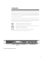
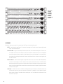
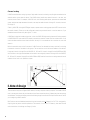
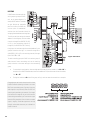
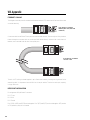
RAVE USER MANUAL FPO ▼ RAVE 80 Digital Audio Router (8 AES3 outputs) ▼ RAVE 81 Digital Audio Router (8 AES3 inputs) ▼ RAVE 88 Digital Audio Router (4 AES3 inputs + 4 AES3 outputs) ▼ RAVE 160 Digital Audio Router (16 analog audio outputs) ▼ RAVE 161 Digital Audio Router (16 analog audio inputs) ▼ RAVE 188 Digital Audio Router (8 analog audio ins + 8 analog audio outs) Rev. A 12345678901234567890123456789 12345678901234567890123456789 12345678901234567890123456789 12345678901234567890123456789 12345678901234567890123456789 12345678901234567890123456789 12345678901234567890123456789 12345678901234567890123456789 12345678901234567890123456789 27 Table of Contents RAVE Digital Audio Router User Manual Warning Notices ................................................................................................................................................ 2 I. Introduction ................................................................................................................................................ 3 Glossary .......................................................................................................................................................... 4 How it works .................................................................................................................................................. 5 II. Network Design ......................................................................................................................................... 6 Network topology examples ......................................................................................................................... 7 Longer distance through fiber ....................................................................................................................... 8 Network limitations ..................................................................................................................................... 10 III. Installation ............................................................................................................................................... 12 Pre-Installation preparation: analog signal levels (RAVE 160, 161, and 188 only) .................................. 12 Rack mounting (all models) ......................................................................................................................... 14 IV. Connections .............................................................................................................................................. 14 Ethernet connection (all models) ................................................................................................................ 14 Analog audio connections ........................................................................................................................... 14 Digital audio connections ............................................................................................................................ 15 AC power ..................................................................................................................................................... 16 Sync output .................................................................................................................................................. 16 Slave input ................................................................................................................................................... 17 RS232 port ................................................................................................................................................... 17 V. Operation ................................................................................................................................................... 18 Status indicators .......................................................................................................................................... 18 Channel signal indicators ............................................................................................................................ 19 Routing ......................................................................................................................................................... 20 VI. FAQ: Frequently Asked Questions ....................................................................................................... 21 VII. Specifications .......................................................................................................................................... 23 VIII. Appendix ................................................................................................................................................... 24 IX. Address & Telephone Information ...................................................................................................... 25 © Copyright 1997 QSC Audio Products, Inc. All rights reserved. “QSC” and the QSC logo are registered with the U.S. Patent and Trademark Office. RAVE™ is a trademark of QSC Audio Products, Inc. CobraNet™ is a trademark of Peak Audio, Inc. 1 EXPLANATION OF GRAPHICAL SYMBOLS The lightning flash with arrowhead symbol, within an equilateral triangle, is intended to alert the user to the presence of uninsulated dangerous voltage within the products enclosure that may be of sufficient magnitude to constitute a risk of electric shock to humans. The exclamation point within an equilateral triangle is intended to alert the users to the presence of important operating and maintenance (servicing) instructions in the literature accompanying the product. EXPLICATION DES SYMBOLES GRAPHIQUES Le symbole éclair avec point de flèche à lintrérieur dun triangle équilatéral est utilisé pour alerter lutilisateur de la presence à lintérieur du coffret de voltage dangereux non isolé dampleur suffisante pour constituer un risque delétrocution. Le point dexclamation à lintérieur dun triangle équilatéral est employé pour alerter les utilisateurs de la présence dinstructions importantes pour le fonctionnement et lentretien (service) dans le livret dinstruction accompagnant lappareil. ERKLÄRUNG DER GRAPHISCHEN SYMBOLE Der Blitz nach unten zeigendem Pfeil in einem gleichseitigen Dreieck weist den Benutzer auf das Vorhandensein einer unisolierten, gefährlichen Spannung im Gehäuse hin, die stark sein kann, einer Person einen elektrischen Schlag zu versetzen. Das Ausrufzeichen in einem gleichseitigen Dreieck weist den Benutzer auf wichtige Betriebs- und Wartungs- vorschriften in den beiliegenden Unterlagen des Gerätes hin. CAUTION RISK OF ELECTRIC SHOCK DO NOT OPEN CAUTION: To reduce the risk of electric shock, do not remove NOTE: This equipment has been the cover. No user-serviceable parts inside. Refer servicing tested and found to comply to qualified service personnel. with the limits for a Class A WARNING: To prevent fire or electric shock, do not expose this digital device, pursuant to Part equipment to rain or moisture. 15 of the FCC Rules. These limits are designed to provide reasonable protection against harmful interference in a commercial installation. This AVIS equipment generates, uses, and can radiate radio frequency RISQUE DE CHOC ÉLECTRIQUE NE PAS OUVRIR energy and, if not installed and used in accordance with the ATTENTION: Pour eviter les risques de choc électrique, ne pas instructions, may cause harmenlever le courvercle. Aucun entretien de pièces intérieures ful interference to radio compar lusager. Confier lentretien au personnel qualifié. munications. Operation of this AVIS: Pour eviter les risques dincendie ou délectrocution, equipment in a residential area nexposez pas cet article à la pluie ou a lhumidité. is likely to cause harmful interference, in which case the user will be required to correct the interference at his or her own expense. VORSICHT GEFAHR EINES ELEKTRISCHEN SCHLAGES. NICHT ÖFFNEN! VORSICHT: Um das Risiko eines elektrischen Schlages zu vermindern, Abdeckung nicht entfernen! Keine Benutzer Wartungsteile im Innern. Wartung nur durch qualifiertes Wartungspersonal. WARNUNG: Zur vermeidung von Feuer oder elektrischen Schlägen, das Gerät nicht mit Regen oder Feuchtigkeit in Berührung bringen! SAFEGUARDS Electrical energy can perform many useful functions. This unit has been engineered and manufactured to assure your personal safety. Improper use can result in potential electrical shock or fire hazards. In order not to defeat the safeguards, observe the following instructions for its installation, use and servicing. PRECAUTIONS DECLARATION OF CONFORMITY for all RAVE models We declare as our sole responsibility that this product is in compliance with the EMC Directive 89/336/EEC and conforms to the requirements of the Harmonized Product Standards EN 55013 (Product Emissions), and EN 55020 (Product Immunity). 2 FEDERAL COMMUNICATIONS COMMISSION (FCC) INFORMATION Lénergie électrique peut remplir de nombreuses fonctions utiles. Cet appariel a été conçu et réalisé pour assurer une sécurité personnelle entiére. Une utilisation impropre peut entraîner des risques délectrocution ou dincendie. Dans le but de ne pas rendre inutiles les mesures de sécurité, bien observer les instructions suivantes pour linstallation, lutilisation et lentretien de lappareil. I. Introduction RAVE Digital Audio Router products provide a means of transporting audio signals over a data network. Using common Fast Ethernet as the physical medium, a RAVE system has a maximum capacity of 64 channels on a 100baseTX network. RAVE transports the audio signals over the network in a 48 kHz 20-bit digital format. Each unit has a female RJ-45 connector on its rear panel for connecting to a standard Ethernet twisted-pair cable. For economy and flexibility, you can use standard off-the-shelf Fast Ethernet devices such as hubs and fiber optic media converters with your RAVE system. You need at least two RAVE devices—one to send and one to receive, or two to both send and receive—to route audio over an Ethernet. There are currently six RAVE models, with three basic send/receive configurations (16 channels send, 16 channels receive, or 8 channels send/8 channels receive), with either analog or digital AES3 (often called AES/EBU) ins and outs. The six models are numbered as follows: RAVE 80 Digital Audio Router (8 AES3 outputs; 16 audio channels total) RAVE 81 Digital Audio Router (8 AES3 inputs; 16 audio channels total) RAVE 88 Digital Audio Router (4 AES3 inputs + 4 AES3 outputs; 8 audio channels total each way) RAVE 160 Digital Audio Router (16 analog audio outputs) RAVE 161 Digital Audio Router (16 analog audio inputs) RAVE 188 Digital Audio Router (8 analog audio inputs + 8 analog audio outputs) A RAVE system handles routing in groups of 8 individual audio channels. Power LED Network channel selector switches (behind cover) Network status LEDs Audio signal level LEDs Front view of a RAVE 161; other models are simliar 3 Rear views, from top: RAVE 160, RAVE 188, RAVE 161, RAVE 80, RAVE 88, and RAVE 81. GLOSSARY Below are some terms used in this manual that RAVE users should be familiar with. AES3—A technological specification for inter-device conveyance of a dual-channel (stereo) digital audio signal. Also called AES/EBU. Crossover cable—A type of twisted-pair Ethernet patch cable, but somewhat analogous in function to a null modem cable. Unlike a normal patch cable, the transmit and receive wire pairs are swapped at one end, permitting a direct connection of two nodes without a hub in between. A crossover cable is also suitable for cascading hubs that don’t have an available uplink port. It also has nothing to do with an audio crossover. Network channel—A RAVE network group of eight audio channels, with a channel number designated by a switch on the sending unit. Don’t confuse this term with actual audio channels. A RAVE network multiplexes eight audio channels onto a single network channel and routes the entire network channel as a whole. A receiving RAVE unit set to a particular network channel will output all eight of the network channel’s audio signals. Uplink port—A special port on a hub, used for cascading to another hub. Usually it’s offered in tandem with a normal port so you can use one or the other, but not both. For example, a 5-port hub with an uplink allows you to connect to five nodes via the normal ports, or to four nodes via normal ports plus one hub via the uplink port. 4 HOW IT WORKS Ethernet networks are most often used for computer systems; a typical application would be in an office with servers, workstations, and shared printers. These devices use the Ethernet medium in an unregulated, nondeterministic way. This means that they transmit data messages (called “packets”) only when necessary, and the length of the messages may vary depending on the sending device and on the type and amount of data being sent. When it has a message to send on the network, a device, or node, waits until there is no traffic, then sends it. If two or more nodes try to send messages at the same time, a collision occurs; each node then waits a random length of time before trying again. In this type of application, reasonable latency (the length of time from when the transmitting node has a message ready to send, to when the receiving node actually receives it) is not a problem, since a second or two delay in the transmission of a print job or an e-mail message won’t have any noticeable effect. Audio signals (especially multi-channel), however, generally can’t tolerate a delay of even a significant fraction of a second, or even worse, a varying, unpredictable delay. This would cause glitches, dropouts, noise, and other nasty and undesirable artifacts in the final audio signal. Internal block diagram of a RAVE unit; chief difference among the different models is the audio I/O (below) Therefore, the CobraNet™ technology used in a RAVE system employs a regulated, deterministic system of packet timing to ensure consistent and reliable transmission without dropouts or glitches. The RAVE devices on a common network will automatically negotiate the time slots among themselves. For efficiency, the sample data from eight audio channels are grouped together in each packet. RAVE 80: 8 AES3 outs RAVE 81: 8 AES3 ins RAVE 88: 4 AES3 ins + 4 AES3 outs RAVE units will synchronize themselves over the network, and they have BNC connectors on the rear panels for sending sync signals. This allows them to synchronize external digital audio equipment to the RAVE network. RAVE 160: 16 analog outs RAVE 161: 16 analog ins RAVE 188: 8 analog ins + 8 analog outs 5 Channel routing A RAVE network handles routing in groups of eight audio channels, and each group of eight transmitted on the network makes up one network channel. Each RAVE device handles two network channels—two sent, two received, or one of each. For example, a RAVE 161 unit, with 16 analog audio inputs, represents two transmitted groups, and thus two separate network channels; one comprises audio channels 1 through 8—the other, channels 9 through 16. Similarly, a RAVE 80, with eight AES3 digital outputs, represents two receiving groups (each AES3 channel carries two audio channels). Either one can be configured to receive any network channel—even the same one, if you needed what would essentially be a digital “Y” cable. A RAVE device that both sends and receives, such as the RAVE 188 (eight analog inputs and 8 analog outputs) or RAVE 88 (4 AES3 inputs and 4 AES3 outputs), transmits one network channel and can receive another. It can receive the same network channel that it transmits, but only if it is connected to a hub or another unit, on a valid network. Behind a removable cover on the front panel of a RAVE unit are four hexadecimal rotary switches for selecting the network channels of the device’s two groups. The two switches on the left set the address of the device’s first group (channels 1 through 8 on the RAVE 80, 81, 160, and 161; inputs 1 through 8 on the RAVE 88 and 188), while the two on the right set the address of the device’s second group (channels 8 through 16 on the RAVE 80, 81, 160, and 161; outputs 1 through 8 on the RAVE 88 and 188). Detailed instructions on setting network channel numbers follow later in the Operation chapter. II. Network Design There are several ways to configure a RAVE network, from very simple to relatively complex. The number of RAVE units in the network, where they are located, and your future expansion plans will determine what net topology would be best. The same techniques you would use in designing a conventional 100-Mbps Fast Ethernet will assist you in designing a RAVE network. RAVE units can use unshielded twisted pair wiring, but it must be at least Category 5 (or CAT-5, for short) quality. Anything less may cause unreliable operation of the network, if it runs at all. Fortunately, most new Ethernet cable installations in buildings use Category 5 cable. 6 NETWORK TOPOLOGY EXAMPLES Two nodes with a direct cable connection Advantages: very low cost; very high reliability; simple to implement Disadvantages: limited to 100 meters (328 feet) total network size; no expandability; uses non-standard wiring of RJ-45 connectors on Ethernet cable The simplest and most direct RAVE network comprises two RAVE units connected by a single crossover cable. This network has only one segment, so the 100-meter limit applies to the segment and thus to the entire network. There are no hardware costs other than the RAVE units themselves and the cable for the interconnection. Also, there are few potential failure points. However, there is no way to connect additional RAVE units without resorting to adding a hub, and because a crossover cable isn’t usually an off-the-shelf item, you’ll probably have to wire it yourself. Two nodes with a 100baseTX hub Advantages: greater network size—up to 200 meters (656 feet); high reliability; readily expandable; uses standard Ethernet patch cables Disadvantages: higher cost This network is similar to the previous one, but with a hub in between, breaking up the network into two segments which can each be up to 100 meters long. Yes, there is the added expense of a hub, and you are adding the slight possibility of a hub failure, but the net media can be simple off-the-shelf patch cables, and you can easily expand the network by connecting additional nodes to the hub. Astute observers and those who read ahead in the manual will notice that this network configuration is really just a star topology with only two nodes. 7 Star topology Advantages: greater network size—up to 200 meters (656 feet); high reliability; readily expandable; uses standard Ethernet patch cables Disadvantages: higher cost Add nodes—i.e., RAVE units—to the previous net layout and you have the classic star topology. This name comes from the hub being at the center and the nodes radiating out from it like the points of a star. It doesn’t matter if the nodes are actually right next to one another while the hub is in another room—it’s still a star topology. You can connect as many RAVE units as there are ports on the hub. Star network topology Distributed star topology Advantages: greater network size; high reliability; readily expandable; uses standard Ethernet patch cables Disadvantages: higher cost What do you do when you have more RAVE units than available hub ports? Add more hubs, of course. Most Fast Ethernet hubs now are stackable, either through an uplink port that lets you connect an additional hub to one already in the network, or through a backplane connection. The resulting network topolgy is called a distributed star, because it is made up of interconnected multiple stars. The maximum UTP cable length from hub to hub, or from hub to RAVE unit, is 100 meters (328 feet). The example shown on the following page uses three hubs. The maximum size of this particular CobraNet network would be 400 meters (1312 feet), allowing two 100-meter cable runs among the three hubs, plus 100-meter cable runs on the end hubs. You can expand the distances even further by daisy-chaining more hubs and cable segments. There are technical and practical limits to this strategy; see the section on network limitations for further information. LONGER DISTANCE THROUGH FIBER Sometimes a network may span long distances without any practical need for hubs distributed along the way. The computer networking industry, on whom we’re already relying for an economical and rugged transport medium, has an answer to this need also: fiber optics. 8 Maximum system cable span (e.g., furthest nodeto-hub + hub-to-hub + hub-to-node): 400 meters (1312 feet) Distributed star network topology Data signals sent over optical fiber don’t degrade as much as they do over copper wiring, and they are immune to induced interference from electromagnetic and RF sources, fluorescent lighting fixtures, etc. Consequently, a Fast Ethernet fiber optic network segment (100baseFX) can be up to 2 kilometers (6560 feet, or 1.24 miles) long, twenty times longer than what is possible with CAT-5 UTP copper wire. Largely due to increased economies of scale, fiber optic cable pricing has become more economical in recent years, so even 62.5 µm multimode fiber is no longer painfully more expensive than CAT-5 UTP. However, because of the added cost of media conversion, it’s usually most cost-effective to use fiber only when distance or electromagnetic conditions require it. 9 The illustration at right shows a simple 2-node network similar to the one decribed before, except nearly all of the interconnecting UTP cable between the RAVE devices has been replaced by a pair of 100baseTX-to-100baseFX converters and a length of fiber optic cable. This conversion to a fiber optic medium allows the distance between the RAVE units to be increased to up to 2 kilometers. More complex topologies with more than one fiber optic link are also possible, as shown below. Although any fiber link may be up to 2000 meters long, the maximum network diameter—the total span from one device to the furthest device—is also slightly more than 2000 meters, allowing for the delays inherent in the other cabling and devices. In the system shown here, Fiber Link A and Fiber Link B can individually be up to 2000 meters, but the total of their lengths should also be 2000 meters or less; For example, Fiber Link A could be 1500 meters, while B would be up to 500 meters; the UTP cabling length will also require adjustments in the maximum lengths. Likewise, the other network topologies described here earlier can be upgraded with optical fiber. This can be done with media conversion on individual network segments, as shown here, or by using fiber to interconnect hubs (illustrated on the following page), or combinations thereof. *Although any one fiber segment can be up to 2000 meters long, and any single UTP segment can be up to 100 meters long, it may be necessary to impose shorter limits, in consideration of cumulative delays caused by devices and cabling. See text for more information. NETWORK LIMITATIONS There are more possible combinations than can be shown in this or any book, and as long as they are compatible with 100baseTX Fast Ethernet standards, they will work with RAVE units. Keep in mind, though, that every hub, length of cabling, media converter, etc., delays the data passing through it by a small amount, and adding these to the system adds to the total delay time. CobraNet has a certain advantage over regular Fast Ethernet, however, 10 * Using optical fiber to link hubs *Although any one fiber segment can be up to 2000 meters long, and any single UTP segment can be up to 100 meters long, it may be necessary to impose shorter limits, in consideration of cumulative delays caused by devices and cabling. See text for more information. in that its deterministic nature affords a bit more tolerance of delay than unregulated, non-deterministic network traffic can handle: a network span or diameter of up to 2560 bit periods (with Fast Ethernet, 1 bit period = 10 nanoseconds), or 25.6 microseconds. Unless you are designing very large and complicated RAVE networks, though, you’re highly unlikely to reach these limits. For further guidance on designing large-scale networks, consult the RAVE Application Guide or see the CobraNet network guidelines on Peak Audio’s web site at http://www.peakaudio.com. As mentioned before, the maximum Category 5 UTP cable length between two network devices—that is, between any RAVE unit, hub, repeater, switch, etc., and any other—is 100 meters, or 328 feet. You can cover longer distances by using optical fiber, as mentioned earlier, or by running 100-meter lengths of UTP cable linked by Fast Ethernet hubs. The latter solution is practical mainly if you need, or are likely to need, RAVE units at the intermediate points, and possible only if you have power sources for all the Fast Ethernet hubs. Ultimately, the cumulative round-trip propagation delays of all the cables (typically 1.112 bit periods/meter) and intervening hubs (Class I hub: < 140 bit periods; Class II hub: <92 bit periods) imposes a limit on how far you can carry this sort of configuration. See the CobraNet network guidelines at the Peak Audio web site (cited above) for further guidance, especially if you are designing a CobraNet network whose span approaches or even exceeds 1000 meters. A fiber optic run of typical 62.5 µm multimode fiber can be up to 2 kilometers, or 6560 feet or 1.24 mile. Singlemode fiber is a much higher grade and can thus handle longer distances, but the specific limit hasn’t been determined, and largely depends on the hardware involved. Consult the manufacturer of the media converters you use. Although a RAVE network has a capacity of 64 audio channels—i.e., eight network channels, each with eight audio channels—there is no set limit to the number of receivers that a RAVE network will support, except that as you add more hubs and cabling, the data delays will increase. 11 III. Installation PRE-INSTALLATION PREPARATION: ANALOG SIGNAL LEVELS (RAVE 160, 161, AND 188 ONLY) The RAVE models which handle analog audio inputs and/or outputs require a signal level set-up to achieve optimum performance. This configuration should be completed before rack-mounting the units. (The digital AES3 models, however, do not require any such adjustment.) These adjustments are done internally by placing or arranging jumpers on the main circuit board. For access to these jumpers, you must first remove the top cover of the RAVE unit as follows. CAUTION: Remove the power cord before removing the top cover. Dangerous voltages within the enclosure may be of sufficient magnitude to constitute a risk of electric shock to humans. To remove cover, first detach the AC power cord, then remove screws from top, bottom, and sides. The arrows in this picture point to the 17 screw locations. Required tools: medium Phillips screwdriver Then lift the rear edge of the top cover about ¼ inch, or 6 mm, and slide the cover forward about 2 inches, or 5 cm. Lift the cover straight up to remove it from the chassis. Re-installing the cover is the reverse of removal. Be sure to take proper protective measures, such as working on an anti-static surface and wearing a grounding wrist strap, before touching any circuitry inside. 12 Input Level Sensitivity (RAVE 161 and 188 only) Input level sensitivity is the rms analog signal level at which a sinusoidal waveform will produce a digital full scale signal in the device. The available settings are +24dBu, +18dBu, and +12 dBu (reference: 0 dBu = 0.775 volt), which are 12.3, 6.1, and 3.1 volts rms, respectively. These correspond to 17.4, 8.7, and 4.4 volts peak. Check the specifications of the audio equipment driving the inputs to determine the correct setting. Each channel’s sensitivity is independent of the others and must be set individually. • First, locate the input sensitivity-selection jumper headers, which are in a row of small groups of pins (6 in each group) on the top side of the circuit board, somewhat midway between the front edge of the board and the rear edge. You’ll see a row of 16 headers on a RAVE 161, or eight on a RAVE 188–one for each channel, in other words. • Determine what the correct setting should be for each channel, and set the jumpers as shown in the illustration. There is also a legend printed on the circuit board showing the jumper setting options. Save any unused jumpers for future use. Output Levels (RAVE 160 and 188 only) The output level setting determines the absolute rms level of an analog signal produced by a digital full scale sinusoidal signal. The four selections available are +24dBu, +18dBu, +12dBu, and +6dBu (reference: 0 dBu = 0.775 volt)—12.3 volts, 6.1 volts, 3.1 volts, and 1.5 volts rms, respectively. These voltages respectively correspond to 17.4, 8.7, 4.4, and 2.2 volts peak.. • As with setting the input level, the output level for each channel is set by arranging jumpers on the pins of a header. These headers are located near the rear edge of the circuit board, and there is one header for each analog output: eight in the RAVE 188, and 16 in the RAVE 160. • Arrange jumpers as shown in this illustration. A legend printed on the circuit board also shows the jumper configurations. Save any unused jumpers for future use. 13 RACK MOUNTING (ALL MODELS) A RAVE unit is 1 RU (1 rack space) high and mounts in any standard 19-inch equipment rack. The top cover of the chassis must be in place and properly secured with screws before you can mount the RAVE unit. • Use four mounting screws to fasten the front ears of the RAVE unit to the mounting rails of the rack. • The chassis of a RAVE unit also has mounting ears on its rear corners; if the rack also has rear rails, it’s a good idea to support the RAVE unit in the rear, too. If you have several units stacked in the rack, at least support the bottom one at the rear corners. • Dress and support any cables that are to attach to the RAVE unit so that their weight doesn’t put an undue strain on their connectors when you attach them. Be careful when installing the unit in an equipment rack; its cooling vents must not be obstructed. Prendre soin lors de l'installation de l'unité dans un bâti d'équipement; on ne doit pas obstruer les bouches de ventilation. IV. Connections ETHERNET CONNECTION (ALL MODELS) A female modular RJ-45 jack on the rear panel is for connecting the RAVE unit to a 100baseTX Ethernet. • To connect the network cable to the RAVE unit, insert the RJ-45 male connector—with its locking tab facing down, the only way the connector will fit into the jack—into the jack until the tab clicks into place, just like connecting a modular telephone cable to a telephone. • To disconnect the network cable from the RAVE unit, grasp the connector and squeeze up on the locking tab, then pull it out of the RJ-45 jack. A 100baseTX network connection requires CAT-5 grade cable. The cable length between the RAVE unit and a 100baseTX hub should not exceed 100 meters (328 feet). Suitable Ethernet cable is readily available at most computer suppliers. To make your own, see the Appendix for connector pinouts. Connecting to Ethernet ANALOG AUDIO CONNECTIONS Analog audio inputs and outputs connect through detachable terminal strip headers on the rear panel of the RAVE unit. These detachable headers allow for pre-wiring of racks and quick connecting and disconnecting for installation, removal, reconfiguration, or replacement. The illustration at right shows how the detachable headers work. To connect a wire to a terminal: • Strip back the insulation on the wire about ¼ inch (approximately 6.3 mm). • Loosen the screw above the header terminal, then insert the wire fully. • Tighten the screw until the wire is firmly anchored. Do not overtighten. • Use a wire tie to secure the cable to the grip of the header block. The detachable headers connect to and disconnect from the pins simply by pushing on and pulling off. 14 To connect balanced inputs, insert the +, -, and shield into the header as shown at left. To connect unbalanced inputs, connect the signal conductor to the + terminal and the shield to the - terminal, with a jumper to the ground/shield terminal, as shown at below left. The analog RAVE models (RAVE 160, 161, and 188) use normal analog balanced audio inputs and outputs, with three terminals per channel: Hi (+), Lo (-) and Shield. Channel numbers and connector pinouts are labeled on the rear of the unit, as shown in the illustration below. The actual channel assignment depends on the model. RAVE 188 This model features 16 analog channels comprising eight inputs and eight outputs. The inputs are labeled 1 through 8 on the rear of the unit and are to the right of the outputs, labeled 1 through 8. RAVE 161 This model features 16 analog audio input channels. They are labeled 1 through 16 on the rear of the unit. RAVE 160 This model features 16 analog audio output channels. They are labeled 1 through 16 on the rear of the unit. DIGITAL AUDIO CONNECTIONS The digital RAVE models (RAVE 80, 81, and 88) use input and/or output interfaces that utilize the AES3 (also known as AES/EBU) digital audio standard. All digital audio inputs on a RAVE unit are terminated as dictated by the AES3 specification. Thus, you will generally need a suitable digital distribution amplifier if any single AES3 source will be driving more than one AES3 input. Also, all AES3 inputs automatically and independently perform digital sample rate conversion. This allows any source device to run asynchronously to the network and to other sourcing devices. Each AES3 input or output carries a pair of digital audio channels through a balanced 3-pin XLR connector. Like analog equipment, outputs use connectors with male pins and inputs use connectors with female pins, and Pin 1 is used for the cable shield and the signal ground. Pins 2 and 3 are for the digital signal, and unlike analog connectors, the relative polarity of the two pins is not important. Channel numbers and connectors are labeled on the rear of the unit, as the illustration shows. The actual channel assignment depends on the model. RAVE 88 This model features eight AES3 channels (16 audio channels): 4 inputs and 4 outputs. The AES3 inputs are labeled 1 through 4 on the rear of the unit and are to the right of the AES3 outputs 1 through 4. 15 RAVE 81 This model features eight AES3 input channels, a total of 16 audio channels. The AES3 inputs are labeled 1 through 8 on the rear of the unit. RAVE 80 This model features eight AES3 output channels, a total of 16 audio output channels. The AES3 outputs are labeled 1 through 8 on the rear of the unit. AC POWER A RAVE unit will operate on line voltages from 90 to 264 VAC, 47 to 63Hz. No user selection of line voltage or frequency is required; the internal power supply automatically switches accordingly. The detachable AC power cord connects to the chassis at the IEC connector. Use only a power source with a protective earth ground. Utiliser une source d'alimentation électrique avec mise à la terre. A RAVE unit has no power switch; the AC disconnect device is the detachable power cord. Les unités RAVE n'ont pas d'interrupteur marche/arrêt; le cordon d'alimentation détachable sert à débrancher l'unité de la source de courant. The IEC connector contains a line filter to minimize susceptibility to RF and EMI from the AC line, and to reduce digital noise that may otherwise get out of the RAVE unit and onto the AC system. The fuse holder is an integral part of the IEC connector, too. It contains two fuses. • To replace a fuse, first detach the AC power cord from the RAVE unit. • Then use a flat-blade screwdriver to pry the fuseholder out, as shown at left. The fuses are held in the round openings in the end of the fuseholder as shown at right. Replace one or both fuses with the same type: 20 × 5 mm, 2 amp, 250V. Replace only with the same type fuse. Remplacer avec un fusible de même type. SYNC OUTPUT At this BNC jack the RAVE unit produces a 5 Vp-p sample rate clock whenever the unit is connected to the network and is operating properly. This clock signal can be used to synchronize external digital audio equipment, and it coincides with the clock signal broadcast over the network. No clock signal is produced if the unit is unable to send or receive any audio channels, or if a fault occurs with the unit. The latter occurrence will be indicated by the Fault LED. 16 2A 250V 20 × 5 mm FUSE (2 required) SLAVE INPUT The slave input is another BNC jack. Its use is to allow a RAVE unit to “slave” itself to another RAVE unit, as a backup in mission-critical applications. To slave one RAVE unit to another, connect a BNC jumper cable from the sync output of the main unit to the slave input of the redundant unit. Select the same network channel(s) on the slave unit as are selected on the main unit. As long as the slave input detects the clock signal from the main RAVE unit, it will maintain a sort of “standby” mode, i.e., if it has analog audio outputs, the output relays will stay open to prevent the production of audio signals; if it has digital audio outputs, the bitstream will continue, but the audio information will be as if the audio channels were muted; if it has analog or digital audio inputs, the unit will not transmit data on the network. However, once the clock signal disappears, as would happen if the main unit detects an internal fault, loses its network connection, or just fails, the slave unit will go into normal operation. If the clock signal re-appears, the slave unit will go back to its standby role. RS232 PORT The RS232 port is an auxiliary function which allows you to transmit serial data over the RAVE network, from one RAVE unit to another. This is handy for remotely controlled accessories and processors that use RS232 data. Serial data format is fixed at 19,200 baud, 9 bits (or 8 bits w/ parity), 1 stop bit. Incoming serial data is buffered and broadcast over the network. All attached stations receive these broadcasts and transmit the data simultaneously out their respective serial ports. When the RS232 electrical connection is in use, the serial port operates in a half duplex mode. For pinout information, see the Appendix. 17 V. Operation STATUS INDICATORS The eight status indicator LEDs display the operating condition of the RAVE unit and its Ethernet network. They are color coded such that green LEDs, when lit, signify something good or normal, while red ones signify a problem. The “Conductor” LED is yellow because it doesn’t signify good nor bad; it’s simply informational. Network activity LEDs Link This LED lights green when the unit is properly connected to an operating Ethernet network. In normal operation, this LED remains constantly lit, as long as the circuitry detects the network carrier. If this LED is not lit, there is a fault, probably at the hub or in the connection between the RAVE unit and the hub. 100 Mbps This LED lights green when the unit is connected to a 100baseTX Ethernet. If it does not light, the network either isn’t established or is a 10baseT Ethernet, and the RAVE system will not work. Rx This green LED lights for 50 milliseconds or longer whenever the unit receives Ethernet data, whether it is addressed to the unit or not. Rx Error This red LED lights for at least 1 second if the unit has trouble receiving a channel for one of the following reasons: ◗ Ethernet data or framing error. ◗ Network timing error; typically caused when transmission is delayed by unregulated traffic on the network. ◗ An internal fault has occurred. The fault indicator will also light in this case. Tx This LED lights green for at least 50 milliseconds while the unit is transmitting Ethernet data. Tx Error This LED lights red for at least 1 second if unit is having trouble transmitting data for one of the following reasons: ◗ An internal fault has occurred. The fault indicator will also light in this case. ◗ The RAVE unit is not connected to an operating network. Conductor This is the aforementioned yellow LED. It lights whenever the unit is the conductor, i.e., it is providing master timing and coordination services for the network. 18 The RAVE units in a common network select a conductor according to three priorities. The priorities are, from highest to lowest: 1. Models 161 and 81 2. Models 188 and 88 3. Models 160 and 80 When a unit is connected to the network, it first looks to see if there is a conductor with lower priority already present. If so, or if there is no conductor present, the unit takes over as conductor. If not, the existing conductor keeps its job. If the conductor of a network is removed or taken offline, the remaining RAVE units choose a new conductor randomly but according to the above three-level order of priority. Whenever the conductor duties change hands, a network outage tens of milliseconds in duration occurs. The conductor indicator helps the operator avoid such outages. Fault This red LED remains lit for at least 10 seconds whenever the unit detects any non-fatal but unexpected internal fault. When a fatal fault is detected, the fault indicator flashes for 10 seconds in combination with channel signal indicators to display a fault code. The unit will then attempt to reset itself to recover from the fault. CHANNEL SIGNAL INDICATORS Also on the front panel are 16 tri-color LEDs. Each one corresponds with an audio channel to indicate its relative signal level: Dim green—when the channel is transmitting or receiving audio data over the network and the audio peak signal level is below -40dBFS (reference: 0 dBFS equals the digital full-scale signal level). Even if the audio signal is muted or drastically attenuated, the LED will stay lit. Bright green—when the channel’s peak level is above -40dBFS (40dB below digital full scale). Yellow—when the signal peaks exceed -12dBFS Red—when the signal peaks reach -2dBFS and above. An output channel’s indicator will not light only if it is assigned to a network channel for which there is no input. In normal operation the channel signal indicators should be flashing bright green or yellow, and perhaps once in a while a quick flash of red. If an LED stays dim green, the signal level is too low and you’re not taking full advantage of the digital headroom. If an LED glows red often and for long durations, the signal level is probably too high and you’ll experience digital “clipping,” which tends to be very harsh. As with any audio device, you should consider the dynamic nature of the program material in judging the correct level indications. 19 ROUTING A RAVE network routes audio signals in groups or groups of 8 channels, as the group diagram of a sample RAVE network illustrates at right. Behind the removable panel on the face of a RAVE unit are two pairs of hexadecimal switches (see the illustration below) for assigning network addresses to the groups. The left two switches assign the network address for the left group, which would be channels 1 through 8 on a RAVE 80, 81, 160, or 161, or the transmitting channels (1 through 8) of a RAVE 88 or 188. Similarly, the right pair of switches assign the network address for the group of channels on the right, i.e., channels 9 through 16 on a RAVE 80, 81, 160, or 161, or the receiving channels (1 through 8) of a RAVE 88 or 188. A typical RAVE network. To make a receiving group of a RAVE unit receive a group of audio channels from a transmitting unit, set the receiving group’s switches to the same settings as the transmitting group. • For transmission and reception, there are eight possible network channel numbers, from 01 to 08. For reception of non-RAVE CobraNet data, there are an additional 247 possible network channel numbers, from 09 to FF. • Setting the switches to 00 shuts off the group, telling it to do no network transmission or reception. One good way to see how the channels work is to have the RAVE network operating, and have one or more RAVE units transmitting (even if you don’t have any audio signals) on any channel(s) from 01 to 08. On a receiving unit attached to the network, flip through the channels 01 through 08. As you hit the channels that are being transmitted, you’ll see that the signal intensity LEDs glow (dimly, if there’s little or no audio signal, or brightly, if the audio signal levels are high enough), and are dark whenever you’re dialed in to a vacant channel. 20 VI. FAQ: Frequently Asked Questions CAN I BUY HUBS, CABLES, AND OTHER EQUIPMENT FOR MY RAVE NETWORK ANYWHERE? Yes. One of the design goals of RAVE technology is that aside from the specialized RAVE devices themselves, all other network-related equipment is common computer equipment available from many sources, including local retail computer stores. Almost all Ethernet patch cables sold in retail stores today are CAT-5 grade, which is the minimum required for a RAVE network. Avoid CAT-3 cable, which is a lesser grade. Fast Ethernet hubs, switches, and media converters are increasingly available from retail and wholesale computer equipment suppliers. DO I NEED A COMPUTER TO RUN OR SET UP MY RAVE NETWORK? No. No computer is needed for setup or operation. Not ever. CAN I ASSIGN MULTIPLE TRANSMITTERS TO THE SAME NETWORK CHANNEL? No. The first unit to transmit on a network channel precludes all other units from transmitting on that same channel. If the two audio channel groups on a single RAVE 81 or 161 are assigned to the same network address, only the first audio channel group (lower eight channel numbers) will be transmitted. You can, however, set transmitters for redundant operation, in which case you actually would set them to the same network channel. In that case, still, only one of the units—normally the master, unless a failure occurs, and then the slave unit will take over—operates at any one time. See Section IV, Connections, for more information on setting up RAVE units for redundant operation. CAN I ASSIGN MULTIPLE RECEIVERS TO THE SAME NETWORK ADDRESS? Yes. Although more than one transmitting group cannot occupy the same network address, multiple receiving groups can, whether they are in the same RAVE unit or separate ones. The network behaves normally, and the RAVE receivers, in effect, act as a distribution amplifier or audio multi. CAN I RUN RAVE UNITS AND AN OFFICE LAN ON THE SAME NETWORK? We don’t recommend it. You might not have any problems if you do, but keep in mind that normal LAN traffic is unregulated and non-deterministic, whereas RAVE network data adheres to a rigid time schedule and packet size. Thus, there is always a possibility that the office traffic will impinge temporally on the RAVE system’s requirements. 21 WHAT HAPPENS IF I RUN OUT OF CHANNELS? Network channels automatically drop when available network bandwidth is exhausted. The network channels with the highest address numbers will be the first to be dropped. The “TX Error” indicator will light when a transmitting unit cannot send due to insufficient bandwidth. If this occurs when the network is carrying additional traffic, such as an office LAN, the unregulated LAN traffic is the likely culprit. Manage and plan any shared network media to avoid such conflicts, and use separate network media whenever possible; if it is absolutely necessary to share media or maintain communication with other parts of a network, use a router to isolate the RAVE portion of the network from the other network devices. CAN I RECEIVE AUDIO CHANNELS ON THE SAME UNIT THAT I TRANSMIT THEM ON? (RAVE 88 AND RAVE 188 ONLY) Audio will loop back within a RAVE unit; that is, if you set the receive channel group to the same network channelas that of the transmitting group on the same unit, the receiving channels will pass the audio signals from the transmitting channels on the same unit. However, the RAVE unit must be connected to an actual network, just as if you were receiving audio from or sending audio to other RAVE units. Of course, there wouldn’t be any point in passing audio from one side of a stand-alone RAVE unit to the other side, anyway. Unlike when you receive a block of audio channels from another RAVE device on the network, when you set the receiving block of a RAVE 88 or 188 to the same channel as the transmit block, the audio signal level LEDs for the receive block will not glow dim green. 22 VII. Specifications Analog Audio Sample rate A/D converters D/A converters Network transmission THD Signal to noise RAVE 161 and 188 inputs: RAVE 160 and 188 outputs: 48 kHz 20 bits 20 bits 20 bits 0.007% worst case, 0.004% @ 1 kHz 104 dB typical; 102 dB worst case, 22 Hz–22 kHz 101 dB typical; 100 dB worst case, 22 Hz–22 kHz Network Data Format Header Packet trailer Standard Ethernet header 4 byte CRC. Network Capacity (without unregulated traffic) 100baseTX 64 channels Unregulated Traffic To maintain continuous maximum performance, we recommend that you do not share the RAVE network with other computer network devices. Gaps are inserted between each data packet to make the network robust to limited unregulated traffic. Recurring management traffic should not seriously affect the network, but large computer file transfers would likely cause audio dropouts. Delay Group Delay Delay through network 6.3 milliseconds or less Delay Variation Guaranteed ±¼ sample periods (±5.28 µs) AC Power 90 to 264 VAC, 47 to 63Hz. No user selection of line voltage or frequency is required; the internal power supply automatically switches accordingly. 23 VIII. Appendix ETHERNET CABLING This diagram shows the pinout for standard unshielded twisted-pair (UTP) network cable. Both ends of the cable are wired identically. RJ-45 pinout for a standard Ethernet patch cable (both ends indentical) A crossover cable has the RX and TX wire pairs switched around at one end. There are only two likely situations that would require a crossover cable: to connect two RAVE devices directly, without a hub or other device in between; and to cascade hubs that don’t have uplink ports. RJ-45 pinout for an Ethernet crossover cable The wire in UTP cabling is twisted together in pairs. Rather than randomly choosing a wiring scheme for the networking cable, it is important to have the RX wires in one pair and the TX wires in another pair, especially in longer cable runs. RS232 PORT INFORMATION Pin assignments of 9-pid female D connector: Pin 2: TX out Pin 3: RX in Pin 5: Ground Pins 1 (DCD), 4 (DSR), and 6 (DTR) are tied together. Pins 7 (RTS) and 8 (CTS) are also tied together. DCE (receives on TD) operation; parity bit not checked. 24 IX. Address & Telephone Information Address: QSC Audio Products, Inc. 1675 MacArthur Boulevard Costa Mesa, CA 92626-1468 USA Telephone Numbers: Main Number (714) 754-6175 Sales Direct Line (714) 957-7100 Sales & Marketing (800) 854-4079 (toll-free in U.S.A. only) Technical Services (714) 957-7150 (800) 772-2834 (toll-free in U.S.A. only) Facsimile Numbers: Sales & Marketing FAX (714) 754-6174 Technical Services FAX (714) 754-6173 World Wide Web: http://www.qscaudio.com BBS/World Group: QSC OnLine Technical Support 1200-14400 bps; 8N1 (714) 668-7567 (800) 856-6003 CompuServe: GO QSCAUDIO ID: 76702,2635 or QSC_AUDIO 25 26 QSC Audio Products, Inc., 28 1675 MacArthur Boulevard Costa Mesa, California 92626 USA PH: (714) 754-6175 FAX: (714) 754-6174 RAVE is a trademark of QSC Audio Products, Inc. “QSC” and the QSC logo are registered with the U.S. Patent and Trademark Office