1
what is included
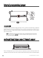
■ The control module
■ A high-powered siren
■ Two 3-button remote transmitters
■ The 12-pin primary harness
■ The plug-in LED system status indicator
■ The 3-pin door lock harness
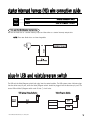
■ The plug-in Valet/Program switch
■ The plug-in starter interrupt harness
■ An on-board zone 2 impact sensor
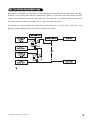
primary harness (H1) wire connection guide
H1/1
H1/2
H1/3
H1/4
H1/5
H1/6
H1/7
______
______
______
______
______
______
______
ORANGE
(-) 500 mA GROUND-WHEN-ARMED OUTPUT
WHITE
(+/-) SELECTABLE LIGHT FLASH OUTPUT
WHITE/BLUE
BLACK/WHITE
(-) 200 mA CHANNEL 3 VALIDITY OUTPUT
(-) 200 mA INTERIOR LIGHT ILLUMINATION OUTPUT
GREEN
BLUE
(-) DOOR TRIGGER INPUT, ZONE 3
(-) MULTIPLEX TRIGGER INPUT, ZONE 1
VIOLET
(+) DOOR TRIGGER INPUT, ZONE 3
H1/8 ______
BLACK
(-) CHASSIS GROUND INPUT
H1/9 ______
YELLOW
(+) IGNITION INPUT, ZONE 5
H1/10 ______
BROWN
(+) SIREN OUTPUT
H1/11 ______
RED
H1/12 ______
RED/WHITE
(+)12V CONSTANT POWER INPUT
(-) 200 mA CHANNEL 2 VALIDITY OUTPUT
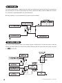
H1/1 ORANGE (-) ground-when-armed 500 mA output
This wire supplies (-) ground as long as the system is armed. This output ceases as soon as the system is disarmed.
It can be used to turn on an optional sensor or to control an optional accessory, such as a window module or
pager.
© 2004 Directed Electronics, Inc. Vista, CA
3