1
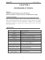
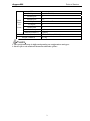
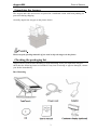
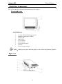
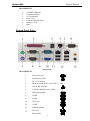
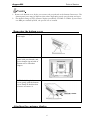
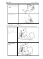
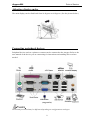
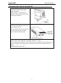
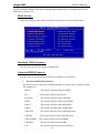
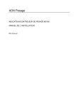
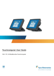
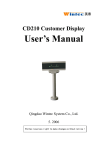
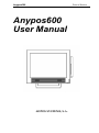
Anypos600 Point of Service Anypos600 User Manual AOPOS SYSTEMS, S.A. Anypos600 Point of Service Copyright This publication, including all photographs, illustrations and software, is protected under international copyright laws, with all rights reserved. Neither this manual, nor any of the material contained herein, may be reproduced or transmitted in any form without express written authorization from AOPOS. Disclaimer The information in this document is subject to change without notice. The manufacturer makes no representations or warranties with respect to the contents hereof and specifically disclaims any implied warranties of merchantability or fitness for any particular purpose. The manufacturer reserves the right to revise this publication and to make changes from time to time in the content hereof without obligation of the manufacturer to notify any person of such revision or changes. Trademark Acknowledgments AOPOS SYSTEMS, S.A. All rights reserved. Other product names mentioned herein may be trademarks or registered trademarks of their respective companies. AOPOS claims no interest in trademarks other than its own. Anypos600 Point of Service Federal Communications Commission (FCC) This equipment has been tested and found to comply with the limits for a Class A digital device, pursuant to Part 15 of the FCC Rules. These limits are designed to provide reasonable protection against harmful interference in a residential installation. This equipment generates, uses, and can radiate radio frequency energy and, if not installed and used in accordance with the instructions, may cause harmful interference to radio communications. However, there is no guarantee that interference will not occur in a particular installation. If this equipment does cause harmful interference to radio or television reception, which can be determined by turning the equipment off and on, the user is encouraged to try to correct the interference by one or more of the following measures: • Reorient or relocate the receiving antenna. • Increase the separation between the equipment and the receiver. • Connect the equipment onto an outlet on a circuit different from that to which the receiver is connected. • Consult the dealer or an experienced radio/TV technician for help. Shielded interconnect cables and a shielded AC power cable must be employed with this equipment to ensure compliance with the pertinent RF emission limits governing this device. Changes or modifications not expressly approved by the system's manufacturer could void the user's authority to operate the equipment. Anypos600 Point of Service Safety information Before installing and using the Anypos, take note of the following precautions: Read all instructions carefully. Do not place the unit on an unstable surface, cart, or stand. Do not block the slots and opening on the unit, which are provided for ventilation. Do not push objects in the ventilation slots as they may touch high voltage components and result in shock and damage to the components. Only use the power source indicated on the marking label. If you are not sure, contact your dealer or the Power Company. The unit uses a three-wire ground cable, which is equipped with a third pin to ground the unit and prevent electric shock. Do not defeat the purpose of this pin. If your outlet does not support this kind of plug, contact your electrician to replace your obsolete outlet. Do not place anything on the power cord. Place the power cord where it will not be in the way of foot traffic. Follow all warnings and cautions in this manual and on the unit case. When replacing parts, ensure that your service technician uses parts specified by the manufacturer. Avoid using the system near water, in direct sunlight, or near a heating device. Anypos600 Point of Service TABLE OF CONTENTS Chapter 1 INTRODUCTION…..................................................................1 About the Product………………………………………………...………1 Specification………………………………………….…………………..1 Unpacking the Anypos……………..………………………………...3 Checking the packaging list………………………………………………3 Identifying Components………………………………………………….4 Removing the bottom cover…………………………………………..….6 Attaching the customer display…………………………………………..6 Attaching the second monitor……………………………………………7 Adjusting display angles………………………………………………….8 Connecting peripheral devices………………………………………..…..8 Powering the Anypos on and off……………………………………..9 Chapter 2 BIOS SETUP UTILITY……..................................................10 Entering the Setup Utility……………………………………………….10 BIOS navigation keys………………………………….………………..10 Using BIOS………………………………………………………...……10 Chapter 3 DRIVER INSTALLATION…................................................14 About Installation………………………………...……………………..14 Software Description………………………………………..…………..14 Driver Installation……………………………………………….………14 Chapter 4 SYSTEM TESTING…............................................................17 About Testing………………………………...…………………………17 CHECK…………………………………..……………………………..17 Setup the Touchscreen…………………………………………………..18 Chapter 5 TROUBLESHOOTING…......................................................22 The Power-On Self Test………………………………...………………22 General Problems………………………………………………………..23 Having the Anypos Serviced………………………………..…...….24 Chapter 6 SERVICE AND MAINTENANCE.........................................25 Anypos600 Point of Service CHAPTER 1 INTRODUCTION Welcome Thank you for purchasing our powerful Anypos! With this manual is to help you operate and maintain the Anypos. About the Product Anypos is an innovational design from Point of Sale terminals and Kiosk with over decade of market experience and product development capability, A full range of functions are designed, developed and produced to meet the requirements of department store, supermarket, hypermarket, convenient store, boutique shops, restaurants, theaters, railway, metro, school, and government projects. Specification CPU Memory Graphics HDD Display Screen Power Supply Audio TouchScreen(Option) Modem(Option) Customer Display(Option) CDROM(Option) IC Card Reader(Option) Barcode Scanner(Option) MSR(Option) WLAN(Option) Mobile communication module(Option) Intel Celeron M CPU 512 MB DDR SDRAM ( up to 1GB) On Board 2.5 inch, 60GB 15 inch TFT LCD,1024*768 pixels 180W Internal ATX or External DC adapter On Board , two-channel AC’97Codec 5 wires resistive / surface wave(SAW) touchscreen PCI interface Vacuum Fluorescent Display (VFD) 2*20 10.4’’ or 15’’ TFT LCD Monitor Slot Load COMBO Smart Card or RF Card Embedded multi-lines laser scanner ( omnidirectional scanning) 3 tracks,ISO7811/7812 ISO802.11b/g Internal GPRS Module 1 Anypos600 Point of Service USB Serial port Back Panel I/O Ports 4 4 (with 5V/12V) Parallel port 1 KB/MS port 1/1 LAN port 10/100 Base-T VGA port 1 Audio jacks 1 Cash drawer port 1(share) Modem port(RJ11) 1(share) Dimension (mm) 370(l) X 280(w) X 340(h) max Weight (standard) 8.5 Kg NOTE: 1. The specification may be different depending on configurations and types. 2. Please refer to the relational documents about the options. 2 Anypos600 Point of Service Unpacking the Anypos The Anypos and cable accessories are packed in a cardboard carton with foam padding for protection during shipping. Carefully unpack the Anypos as the picture below. NOTE: Please keep the packing materials if you need to ship the Anypos in the future. Checking the packaging list Anypos can be fixed in Base Mounting or Wall Mounting. After you unpack the Anypos, check that the following items are included. If any item is missing or appears damaged, contact your dealer immediately. Base Mounting 3 Anypos600 Point of Service Identifying Components This section describes the parts and connectors on the Anypos. Front-right view DESCRIPTION 1 2 3 4 5 6 7 8 9 15-inch TFT LCD and touch screen Magnet Stripe Reader ( MSR ) Power LED HDD LED IC Card LED Power button Front Line-Out jack Speaker RF card reader antenna NOTE:When you use front Line-Out jack, no voise will be out from the speakers. Right view 4 Anypos600 Point of Service DESCRIPTION 1 2 3 4 5 6 7 COMBO CDROM Customer Display IC Card Reader Rear Cover Customer Display Base Bottom Cover Base Bottom Panel Ports (Anypos616) DESCRIPTION 1 PS2 mouse port 2 Parallel port (LPT) 3 DC +12V Output +12V 4 Modem or cash drawer port (RJ11) DK 5 10/100 NIC port1&2 6 Customer Display port (COM4) 7 PS2 keyboard port 8 COM2 9 COM1 10 VGA port 11 COM3 12 USB 1&2&3&4 13 Line-out Microphone 5 CD Anypos600 Point of Service NOTE: 1、 Remove the bottom cover before you connect the peripherals to the bottom Connectors. The bottom panel ports may be different from others depending on the specification and types. 2、 The default setting of VFD customer display port(RJ45) is COM2 or COM4. If you want to use DB9 port instead of RJ45, the special wire is needed. Removing the bottom cover 1. Rotate the display until it’s max angle. 2. Press bottom of the front panel with your thumbs, and press triangle sign at back of bottom cover with other fingers. 3. While holding the bottom cover gently, pull the bottom cover firmly in the direction of arrow to remove it. Attaching the customer display 6 Anypos600 Point of Service 1. Connect the customer display cable to Customer Display port on the bottom panel. 2. Secure the display with four supplied screws. Attaching the second Monitor 1. Connect the signal cord of the second monitor to the VGA port, through the hole of stand base, the power cord is the same, connect to DC +12V Output.. 2. Secure the display with four supplied screws. 7 Anypos600 Point of Service Adjusting display angles The main display can be tilted back from 10 degrees to 66 degrees. (See the picture below.) Connecting peripheral devices Peripheral devices such as a printer or scanner can be connected to the Anypos. Refer to the user manual of the device you are connecting for instructions on installing drivers where needed. (Anypos616) NOTE: The bottom port board may be different depending on configurations and types. 8 Anypos600 Point of Service Powering the Anypos on and off 1. Remove the bottom cover. Connect the power cable to the power connector on the Anypos , Connect the AC adapter to an electrical outlet.(only for External Adapter) 3. Press the power button on the underside of the display panel. The power LED turns on. To turn off the Anypos, shut down the operating system: the main power turns off automatically. 4. There are 2 ways to turn off the Anypos: Click “Start” button, and then “Turn Off Computer”, “Close”; Use the main power button to turn off the power, for example if the operating system you are using does not support power down by the OS or if the system crashes or hangs. Recommended turning off: 1) 9 Anypos600 Point of Service CHAPTER 2 BIOS SETUP UTILITY The BIOS (Basic Input and Output System) Setup Utility displays the system's configuration status and provides options to set system parameters. The parameters are stored in battery-backed-up CMOS RAM that saves this information even when the power is turned off. When the system is turned back on, the system is configured with the values found in CMOS.The following topics are described in this chapter. NOTE:BIOS SETUP UTILITY covers some very technical items and it is strongly recommended that only experienced users should make any changes to default settings. Entering the Setup Utility Press the delete key <Del> to access the Award BIOS Setup Utility. BIOS navigation keys The BIOS navigation keys are listed below. KEY ←↑↓→ +/–/PU/PD Esc Tab F1 F10 Shift + F2 FUNCTION Scrolls through the items on a menu Modifies Exits the current menu Select the field's values Displays a screen that describes all key functions Saves the current configuration and exits Setup Changes the color of the BIOS menu Using BIOS The BIOS Setup Utility enables you to configure items, such as Hard drives, peripherals Video display type, Password protection from unauthorized use and Power management features, etc. This Setup Utility should be used for changing the system configuration, trying to resolve IRQ 10 Anypos600 Point of Service conflicts, making changes to the Power Management configuration, and changing the User or Supervisor password, etc. Main Screen When you start the Setup Utility, the main menu appears. See the picture below. Standard CMOS features Use this menu to set basic system configuration. Advanced BIOS Features Use this menu to set the advanced features available on your system. First/Second/Third Boot Device Set the boot device sequence as BIOS attempts to load the disk operating system. The settings are: HDD-0 The system will boot from first HDD. SCS The system will boot from SCSI. CD-ROM The system will boot from CD-ROM. HDD-1 The system will boot from second HDD. HDD-2 The system will boot from third HDD. HDD-3 The system will boot from fourth HDD. USB-FDD The system will boot from USB floppy drive. USB-ZIP The system will boot from USB ZIP drive. USB-CDROM The system will boot from CDROM. USB-HDD The system will boot from HDD. LAN The system will boot from network drive. 11 Anypos600 Point of Service Disable this sequence. Disabled Default setting:USB-ZIP/ CD-ROM/HDD-0 Advanced Chipset Features This menu is used for optimizing the chipset functions. Boot Display This setting refers to the type of display being used with the system Default setting: CRT+LEP Panel Number This item is used to select the number to support LVDS panel. Default setting: 3 Integrated Peripherals Use this menu to set onboard peripherals features. OnChip LAN This setting allows you to make OnChip LAN enabled or disabled. Settings: Enabled and Disabled. Default value setting: Enable. USB Keyboard Support Enable USB Keyboard Support for DOS and Windows. Settings:Enable and Disabled. Default setting: Enable. Onboard LAN Enables the onboard LAN controller. Settings :Enable and Disabled. Power Management Setup The Power Management Setup menu configures the system to most effectively save energy while operating in manner consistent with your own style of computer use. Power Off by PWRBTN This field configures the power button function. Settings are: Delay 4 Sec The system is turned off if power button is pressed for more than four Instant-off The power button functions as a normal power-on/-off button. seconds. Default setting:Delay 4 Sec PnP/PCI Configurations This option configures how PnP (Plug and Play) and PCI expansion cards operate in the system. Both the ISA and PCI buses on the mainboard use system IRQs (Interrupt 12 Anypos600 Point of Service ReQuests) and DMAs (Direct Memory Access). PC Health Status This section shows the status of your CPU, fan, warning for overall system status. Frequency/Voltage Control Use this menu to set DRAM voltage, DRAM clock, and DRAM timing, etc. Load Fail-Safe Defaults This option on the menu allows users to restore all the BIOS setting to the default Fail Safe values. These values are set by manufacturer to provide a minimal and stable system. Load Optimized Defaults This option on the main menu allows users to restore all the BIOS settings to the default Optimized values. The Optimized Defaults are the default values also set by the manufacturer for both optimized and stable performance of the mainboard. Set Supervisor Password This option on the main menu allows supervisor to set password. Set User Password This option on the main menu allows user to set password. Save & Exit Setup Option To quit the Setup Utility and save the user setup changes to RTC CMOS. Exit Without Saving To quit the Setup Utility without saving any changes to RTC CMOS. 13 Anypos600 Point of Service CHAPTER 3 DRIVER INSTALLATION About Installation The driver utilities and software are installed by following methods: 1. Install from the CD drive. 2. Install from the USB CDROM, USB-HDD/ ZIP/FDD or Flash disk. 3. Install from internet. NOTE: If the system boots from the USB device, configure the BIOS Setup Utility first. (See the BIOS SETUP UTILITY on Chapter 2) Software Description HDD or CD contains driver utilities and software after manufactured. The directory are as below: DRIVERS: CHIPSET VGA AUDIO LAN USB TOUCHSCREEN MODEM // Enhances the chipset. // Enhances the graphic chip. // Enhances the audio chip. // Enhances LAN chip. // USB2.0 driver // Enhances Touchscreen chip // Enhances Modem chip NOTE:DRIVERS’ directories are configured according to the type of the Anypos. Please select your Anypos a directory depending on the type of Anypos. TOOLS: CHECK Self Test Program DLL Device Link Library (DLL) for device KEYBOARD Keyboard Programming Software MANUAL Manual and peripheral instruction DOSNET Client software to Access Server for DOS. All above can be downloaded from our website (www.aopos.com) Driver Installation Please install the driver utilities as the following sequences, otherwise it may result in unpredictable circumstances, such as: unstable system, display mistake, etc, and even you may 14 Anypos600 Point of Service have to reinstall the operating system. Driver Installation of Chipset The Chipset Driver is on \DRIVERS\CHIPSET subdirectory, run SETUP.EXE and install driver on prompt, after completing installation, reboot the computer. Driver Installation of VGA The VGA Driver is on DRIVERS\VGA letter, run SETUP.EXE and install driver on prompt, after completing the installation reboot the computer. Driver Installation of Audio The Audio Driver is on your DRIVERS\AUDIO letter, run SETUP.EXE and install driver on prompt. Driver Installation of LAN The LAN Driver is on your DRIVERS\LAN letter, run SETUP.EXE and install driver on prompt. Driver Installation of Modem The Modem Driver is on your DRIVERS\Modem letter, run SETUP.EXE and install driver on prompt. Driver Installation of 5-wire-resistive touchscreen 1. The 5-wire-resistive touchscreen Driver is on DRIVERS\TOUCHSCREEN\5WIRE letter, run SETUP.EXE and install driver on prompt., then reboot the computer. 2. Double-click the "TouchKit" icon on the desktop, you should change your touchscreen settings before you use it (For more information about touchscreen Settings, please refer to Calibration of the Touchscreen on chapter 4). Driver Installation of SAW Touchscreen The Touchscreen Driver is on DRIVERS\TOUCHSCREEN\SAW subdirectory, the installation may be difference depending on your operating systems. NOTE: You must have administrator access rights on your Windows 2000/XP system to install this software. You must also have administrator access rights to run the touchscreen control panel and calibration applications. 1. Installing touchscreen driver for Windows 2000/XP 15 Anypos600 Point of Service A). If Windows start the New Hardware Wizard Choose Next. Select "Search for the best driver for your device (Recommended)" and Choose Next. When a list of search locations is displayed, place a checkmark on "Specify a location" and use Browse to select the DRIVERS\TOUCHSCREEN\SAW subdirectory on CDROM or HDD. Choose Next. Once the GeneralTouch Touchscreen USB Interface driver has been detected choose Next again. Wait while driver files are copied to your computer. Insert your Windows CD if prompted. Choose Finish. B). If Windows DOES NOT START the New Hardware Wizard After Windows loads, click the "Start" button, and then click "Control Panel", "System", "Device Manager". In the Device Manager, right click on the USB Human Interface Device, and then click on Properties, Driver tab, Update Driver, Next. Select "Search for the best driver for your device (Recommended)" and Choose Next. When a list of search locations is displayed, place a checkmark on "Specify a location" and use Browse to select the DRIVERS\TOUCHSCREEN\SAW subdirectory on CDROM or HDD. Choose Next. Once the GeneralTouch Touchscreen USB Interface driver has been detected choose Next again. Wait while driver files are copied to your computer. Insert your Windows CD if prompted. Choose Finish. 2. Double-click the "GeneralTouch Touchscreen" icon in "Control Panel",you can change your touchscreen settings, (For more information about touchscreen Settings,please refer to Calibration of the Touchscreen on chapter 4) NOTE: The Anypos maybe installed the third-part software in the testing process, but the software is only used for test, and it was deleted before shipping. 16 Anypos600 Point of Service CHAPTER 4 SYSTEM TESTING This chapter gives you detailed explanation of system testing functions. About Testing 1. 2. The CHECK.EXE is a test program in TOOLS subdirectory in your CD or your HDD, which is for test of the Printer, the CustDisplay, the Keyboard, the Drawer, MSR, Scanner, IC Card Reader and Ports. After completing driver installation of Touchscreen, the “GeneralTouch Touchscreen”will install automatically in “Control Panel” which helps to calibrate and setup the touchscreen. CHECK The main menu contains of five items: SET、CHECK、 HOT、EXIT and HELP. Please enter the SET for configuration first, otherwise it may result in incorrect testing. SET― The items are for users to set the system’s configuration, including Printer, CustDisplay, KeyBoard, Drawer, MSR, Scanner, IC CardReader and Port, etc. You can use up/down/left/right Arrow Keys to highlight the field and change the configuration by PgUp/PgDn, (Refer to Product Instruction for more settings). Save the changes and exit press F2. CHECK― The submenu includes some items, such as Printer, CustDisplay, KeyBoard, Drawer, MSR, Scanner, IC CardReader and Port, etc. Printer: Tests the printer. Input numbers and characters the printer begin to print. 17 Anypos600 Point of Service Ensure the printer prints the same as the typing on the screen. Return from the sub-menu press Esc. CustDisplay: Tests the customer display. Ensure the customer display shows the same numbers and characters as input on prompt. Return by pressing Esc. KeyBoard: Tests the keyboard, ensure the character and ASCII code displaying on the screen is the same as the key you press on prompt. Return from the sub-menu press Esc. Drawer: Tests the drawer. Open and close the drawer, ensure the screen shows the status correctly: open, close. MSR: Tests the Magnet Stripe Reader. Scan a credit card and ensure data scanned correctly by seeing applicable information on all three tracks from the credit card. Return from the sub-menu press Esc. Scanner: Test the Scanner. Scan the barcode on prompt and ensure the information on the screen. Return from the sub-menu press Esc. IC CardReader: Tests the IC CardReader. Insert IC Card on prompt, the item will test the device connection and IC card read and written. Port: Tests the serial ports and parallel ports on the mainboard. HOT――For QA EXIT―― Quit Setup the Touchscreen Setup the 5-wires-resistive Touchscreen After successfully installing the diver, the following icons will appear on your desktop. click on the “TouchKit” icon on the desktop, the system will enter calibration interface. 18 Anypos600 Point of Service General User can select the controller list in the windows to do configuration for it. Tools 4 Points Calibration:It needs calibration before the touchscreen work accurately. Clear and Calibrate:To erase the 25 points calibration/linearization parameters and force user to do 4 points calibration again. 19 Anypos600 Point of Service Linearization:is used to compensation the touchscreen linearity. Draw Test:is used for accuracy and performance check. Setting Beep: 1) Beep On Touch: Linearization Style:Touchkit utility provides user with 9 points and 25 points calibration for linearization. Double Click Time:is used to set system double click time. Change this value will affects the double click behavior for all of the mice devices in the system. Double Click Area:is used to set the system double click area. Change this value will affects the double click behavior for all of the mice devices in the system. Normal Mode:User can set configuration for 5 mouse emulation modes for Touchkit touchscreen controllers. Option:User can set configuration for some advanced functions with this option button. Edge Compensation Edge compensation is used to set the touchscreen more accurately. 20 Anypos600 Point of Service 21 Anypos600 Point of Service CHAPTER 5 Troubleshooting Often after time spent troubleshooting, the problem is traced to something as simple as a loose connection. Check the following before proceeding to the problem-specific solutions. The Power-On Self Test The Power-On Self Test (POST) runs every time you turn on or reset the computer. The POST checks memory, the mainboard, the display, the keyboard, the disk drives, and other installed options. If failure is detected in an area other than the mainboard (such as the keyboard or an adapter card), an error message is displayed on the screen and testing is stopped. If your system does not successfully complete the POST, but displays a blank screen, have the Anypos serviced. Beep Errors at POST There are two kinds of beep codes in the BIOS. *Video error - a single long beep followed by three short beeps indicates a video error, the screen can not be initialized and no information can be displayed. *DRAM error - a single long beep indicates that a DRAM error has occurred. Beep Message Errors at POST If the BIOS detects an error during the POST, a message is displayed. Refer to the following table for a list of the errors that display. ERROR MESSAGE CAUSE SOLUTION CMOS BATTERY HAS FAILED The CMOS battery is depleted. Replace the battery. CMOS CHECKSUM ERROR The battery may be weak. The CMOS may be corrupt. Replace the battery. Have the Anypos serviced. HARD DISK(S) FAIL (80) HARD DISK(S) FAIL (40) HARD DISK(S) FAIL (20) HDD reset failed. HDD controller diagnostics failed. HDD initialization error. 22 Have the Anypos serviced. Have the Anypos serviced. Have the Anypos serviced. Anypos600 Point of Service HARD DISK(S) FAIL (10) KEYBOARD IS LOCKED OUT UNLOCK THE KEY Unable to recalibrate fixed disk. The keyboard is locked and the key-board controller is pulled low. Have the Anypos serviced. KEYBOARD ERROR OR NO KEYBOARD PRESENT A keyboard is not detected. Make sure the keyboard is attached correctly and no key is pressed during boot. MANUFACTURING POST LOOP System keeps rebooting because the keyboard controller is pulled low for testing purposes. Have the Anypos serviced. BIOS ROM CHECKSUM ERROR - SYSTEM HALTED The ROM address is incorrect. Have the Anypos serviced. MEMORY TEST FAIL The memory card is not correctly installed or is damaged. Have the Anypos serviced. Have the Anypos serviced. General Problems Refer to the following general problems you may encounter. PROBLEM SOLUTION The display screen is dark. Make sure that the Power LED is on and Anypos is not in suspend mode, and adjust the display brightness. An incorrect date and time are displayed. Correct the date and time using the DOS DATE and TIME commands or the options in the Setup Utility. (You can also set the date and time in Windows by double clicking the clock on the task bar or in the control panel.) If the date and time become incorrect after a short time, the CMOS battery may be depleted. Replace the battery. The following message appears at boot up: “Invalid system disk, Replace the disk, and then press any key” You hear irregular beeps during operation of the computer and the system halts. An unidentified message is displayed. You cannot operate the printer. Ensure that an operating system is installed. Check the boot sequence in the BIOS setup utility. Have the Anypos serviced. Reboot the computer and run the BIOS Setup Utility. Confirm the Setup Utility parameters. If the same message is displayed after booting up again, Check the printer cable connection. Ensure that the printer power switch is turned on. Confirm that the printer is on-line. 23 Anypos600 Point of Service Check the cable connection. Check the mouse or keyboard with another computer to see if it works. If the same problem occurs, replace the mouse or keyboard. Otherwise, have the Anypos serviced. Check that the power cord is plugged into a working The screen is blank and you electrical outlet (and the adapter is connected to the don't hear any beeps. Anypos if there is any). Check that the power is on. (Press the power switch again for confirmation.) The screen is blank and you Have the Anypos serviced. hear a continuous beep, or two or more beeps. Reinstall the operating system, and power on the Only the cursor appears. Anypos. You cannot use a mouse or keyboard. Audio problems Ensure the audio cable is not defective. The mute is off. Having the Anypos Serviced If you are unable to solve the problem, you should have the Anypos serviced. Pack the Anypos in the original carton. Include a description of the problem and a checklist of the steps you took when trying to fix the problem. The information may be useful to the service personnel. Return the Anypos to the place you purchased it. 24 Anypos600 Point of Service CHAPTER 6 WARRANTY For your legal rights, AOPOS promise you offer the warranty and service according to following standard: 1. Duration of limited warranty 1 year warranty. 2. Online Service You can obtain help from AOPOS when you are unable to solve the problem. Please contact our ser and Maintenance Department for any requires. Hotline:400-708-9898. Our service engineers will provide the most efficient help, or visit our website: www.aopos.com to obtain help online. 3. Limitations of warranty Anypos limited warranty covers only those that arise as a result of normal use of the product, and does not cover any other problems, including those that arise as a result of: The entire or spare parts are out of the warranty period; Improper installation, modifications, maintenance; Unauthorized installation/uninstallation , modification or misuse; Software, media, parts, or supplies not provided or supported by AOPOS; Unpredictable factor and personal cause, includes computer virus, improper input voltage, shipping, transport, etc. Operation outside the product’s instruction; Natural hazards or force, such as earthquake and fire; 3. For complete warranty details please ask our office, agents, and Service and Maintenance Center, go to visit our website for the list of support telephone number. 25