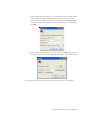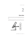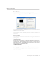
1
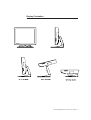
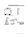
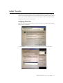
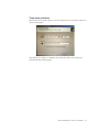
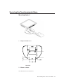
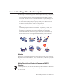
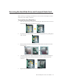
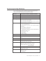
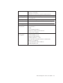
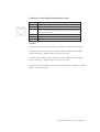
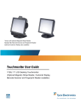
Touchcomputer User Guide
15A2 15" LCD Multifunction Touchcomputer
[Model ESY15A2]
Elo TouchSystems Touchcomputer
User Guide
15" LCD Multifunction Touchcomputer
15A2
Revision B
P/N E293646
Elo TouchSystems
1-800-557-1458
www.elotouch.com
Copyright c 2008 Tyco Electronics. All Rights Reserved.
No part of this publication may be reproduced, transmitted, transcribed, stored in a
retrieval system, or translated into any language or computer language, in any form or by
any means, including, but not limited to, electronic, magnetic, optical, chemical, manual,
or otherwise without prior written permission of Elo TouchSystems.
Disclaimer
The information in this document is subject to change without notice. Elo TouchSystems
makes no representations or warranties with respect to the contents hereof, and
specifically disclaims any implied warranties of merchantability or fitness for a
particular purpose. References in this publication to Elo TouchSystems products or
services do not imply that Elo TouchSystems intends to make them available in all
countries in which Elo TouchSystems operates. Elo TouchSystems reserves the right to
revise this publication and to make changes from time to time in the content hereof
without obligation of Elo TouchSystems to notify any person of such revisions or
changes.
Trademark Acknowledgments
IntelliTouch, SecureTouch, AccuTouch, MonitorMouse, TE logo, and Tyco Electronics
are trademarks. Other product names mentioned herein may be trademarks or registered
trademarks of their respective companies. Tyco Electronics claims no interest in trademarks other than its own.
Elo TouchSystems 15A2 User Guide 3
Table of Contents
Chapter 1
Setup
6
Unpacking Your Touchcomputer ......................... 6
Product Overview ................................................ 7
Front View ..................................................... 7
Rear View ....................................................... 7
Side View ....................................................... 8
Base Bottom View ......................................... 8
Display Orientation ....................................... 9
Display Orientation with Peripherals ............. 10
Initial Turn-on ...................................................... 11
Language selection ....................................... 11
Time Zone ..................................................... 13
Test Devices ........................................................ 14
Touchscreen ................................................. 14
Calibration ................................................. 14
Magnetic Stripe Reader (MSR) ..................... 15
Testing in USB MSR Keyboard
Emulation Mode ........................................ 15
Testing in USB-HID Class MSR HID
Mode ..................................................... 15
Convert Keyboard Emulation/HID Mode . 16
Customer Display .......................................... 17
Fingerprint Reader ........................................ 18
Barcode Scanner ........................................... 19
Enabling 2-D Scanning .................................. 21
Speaker Bar .................................................. 22
Wireless Card ............................................... 23
TV Tuner ....................................................... 23
Cash Drawer Port .......................................... 24
Chapter 2
Operation
26
OSD Control ......................................................... 27
OSD Menu .................................................... 27
Shortcut keys ............................................ 28
OSD Lockout ................................................. 28
Power Control ...................................................... 29
Power Button ................................................ 29
Power Lockout .............................................. 29
Using the I/O panel .............................................. 30
USB and Powered USB ................................. 30
Cash Drawer ......................................... 30
Ethernet ................................................ 30
Serial .................................................... 30
Microphone Input ................................ 30
Audio Output ....................................... 30
VGA ..................................................... 31
PS/2 Universal ...................................... 31
TV Tuner .............................................. 31
Kensington Lock .................................. 31
Securing the Touchcomputer Base ............. 32
Display Angle ............................................. 34
Chapter 3
Upgrades
35
Adding Peripherals ..................................... 35
Chapter 4
Maintenance
36
Care and Handling ...................................... 37
Warning ............................................... 37
WEEE Directive .................................... 37
Servicing the Hard Disk Drive and
Compact Flash card ..................................... 38
To Install the Hard Disk Drive .............. 38
To Install the Compact Flash card ........ 39
Recovering the Operating System .............. 39
Chapter 5
Technical Specifications
40
Touchcomputer Specifications ................... 41
COM1/2 Pin Definition ......................... 43
Power Input Pin Definition ................... 44
Cash Drawer Port Signal Definition
and Control ...................................... 45
Display Specifications ................................ 46
Power Supply Specifications ...................... 47
Touchscreen Specifications ........................ 48
Peripheral Specifications ............................. 49
Magnetic Stripe Reader (MSR) ............ 49
Customer Display ................................. 49
Fingerprint Reader ............................... 50
Barcode Scanner .................................. 51
Elo TouchSystems 15A2 User Guide 4
Speaker Bar .............................................. 52
Wireless Card ........................................... 53
TV Tuner .................................................. 53
Modem Card ............................................ 54
Environmental Specifications .......................... 55
Temperature Ranges ................................ 55
Humidity .................................................. 55
Altitude .................................................... 55
Chapter 6
Technical Support
56
Technical Assistance ...................................... 56
Using the Touchcomputer ....................... 56
Using the Web ......................................... 56
Using the Phone ...................................... 56
Regulatory Information 57
Warranty 60
Elo TouchSystems 15A2 User Guide 5
C H A P T E R
1
Setup
This chapter discusses how to set up and test your touchcomputer and any included
peripheral options.
Unpacking Your Touchcomputer
Check that the following items are present and in good condition:
OR
Touchcomputer
PS2/Y cable
Power cable US/Canadian
CD and Quick Install Guide
European power cable
Power Adapter
DB9 adapter cable
Elo TouchSystems 15A2 User Guide 6
Product Overview
Front View
Rear View
Note: Shown with optional peripherals
Elo TouchSystems 15A2 User Guide 7
Side View
Note: Shown with optional peripherals
Base Bottom View
Elo TouchSystems 15A2 User Guide 8
Display Orientation
Elo TouchSystems 15A2 User Guide 9
Display Orientation with Peripherals
Elo TouchSystems 15A2 User Guide 10
Initial Turn-On
The initial setup of the operating system takes approximately 5-10 minutes. Additional
time may be needed depending on touchcomputer hardware configuration and connected
devices. To setup the Windows OS for the touchcomputer, turn on the touchcomputer
and follow the instructions on the screen.
Language Selection
When the following window appears, you have the option of changing the language
used in menus and dialogs.
Click Customize. The Regional and Language window shown below will appear.
Elo TouchSystems 15A2 User Guide 11
Select the Language tab. The window shown below will appear.
Select the desired language in the drop-down list labeled Language used in menus
and dialogs.
Elo TouchSystems 15A2 User Guide 12
Time-zone selection
When the following window appears, you may change the time-zone, date, and/or time
of the touchcomputer.
After making any changes, click Next to finish. Windows Setup will complete the
initialization of the touchcomputer.
Elo TouchSystems 15A2 User Guide 13
Test Devices
The touchcomputer can be pre-installed with several different hardware options. To test
an optional device that is installed on the touchcomputer, follow the instructions below.
NOTE: Testing icons are located on the desktop. Testing of a particular device can
only be done after the device is properly installed.
Testing the Touchscreen
The touchscreen is pre-calibrated for accurate touch response.
Calibration*
If for any reason the touchscreen needs to be re-calibrated, double-click the TouchscreenTest icon. The window shown below will open.
Click on the Align button. This launches the calibration program. The window shown
below will open. Follow the instructions to calibrate the touchscreen.
*Calibration may not be applicable for all touch technologies.
Elo TouchSystems 15A2 User Guide 14
Testing the Magnetic Stripe Reader (MSR) (optional)
Testing in USB MSR Keyboard (KB) Emulation Mode
1. Double-click the KB MSR Test icon to open the Notepad application
2. Slide the card through the MSR and verify that the data is displayed in the application
window.
Testing in USB MSR Human Interface Device (HID) Mode
1. Double-click the HID MSR Test icon to start the test application.
2. Click the Read Cards button.
3. Slide the card through the MSR and verify that the data is displayed in the application
window.
Elo TouchSystems 15A2 User Guide 15
Converting MSR from Keyboard Emulation to HID and vice versa
1. Double-click the MSR Change Mode icon to start the switch application.
2. Click on HID Mode to switch to HID mode OR click on Keyboard Mode to switch
to Keyboard mode. The dimmed box will indicate the current setting.
3. Click Quit to close the window.
Elo TouchSystems 15A2 User Guide 16
Testing the Customer Display (optional)
1. Double-click the CustDisplay Test icon.
2. Verify that the device shows "EloTouch Systems Customer Display" on the
display.
Elo TouchSystems 15A2 User Guide 17
Testing the Finger Print Reader (optional)
1. Double-click the Fingerprint Reader Test icon to start the test application.
2. Place your finger on the fingerprint reader sensor and verify that the image of your
fingerprint is displayed on the application window.
Elo TouchSystems 15A2 User Guide 18
Testing the Barcode Scanner (optional)
1. Determine which port the barcode scanner is using:
a. In Windows Control Panel, start the Computer Management application
b. In Computer Management, select Device Manager. In the Right pane, look
under the Ports section, and note the COM value of the USB -Serial Port object.
2. Double-click on the Barcode Scanner Test icon to start the following application:
Elo TouchSystems 15A2 User Guide 19
1. Change the port value to match the value you retrieved from the Device Manager.
2. Click Connect. You should see the text Connected in the Messages field.
3. In the box labeled Param Number, enter the value 238.
4. In the box labeled “New Value” enter the value 1.
5. Check the box labeled Permanent Param Change.
6. Scan a barcode. The result should look similar to the following image:
Elo TouchSystems 15A2 User Guide 20
Enabling 2-D Scanning:
The scanner default settings do not enable 2-D barcode reading ability. In order to
enable this option, follow these steps:
• Scan the barcodes below to enable PDF417 and MicroPDF417. These are both
types of 2-D barcodes.
• Now scan the barcode below to change the scanning pattern. Using this
scanning pattern will allow you to read 2-D barcodes (you can still read 1-D
barcodes also).
Elo TouchSystems 15A2 User Guide 21
Testing the Speaker Bar (optional)
To test the speaker bar, play any audio file on the touchcomputer and verify the sound
emitting from the speakers.
NOTE: If the speaker bar is connected to the touchcomputer, the internal speakers
will be disabled. If there is an audio cable plugged into the audio output port on the I/
O panel, both internal and speaker bar speakers will be disabled.
Elo TouchSystems 15A2 User Guide 22
Testing the Wireless Card (optional)
To test the wireless card:
1. From the desktop, click Start->Control Panel->Network Connections
2. Double-click the Wireless Network Connections icon to display available networks
and verify that the wireless network is detected.
Note: If a wireless network needs to be initialized, please see your system administrator.
Testing the TV tuner (optional)
To test the TV tuner, first ensure that the TV Tuner driver and software application
accompanying the card has been installed on the touchcomputer. Also, ensure that a TV
source is properly connected to the TV input connector on the I/O panel.
• To test the TV tuner, run the TV Tuner software application and verify that the video
source is displayed in the application window and audio is emitting from the speakers.
Note: Concurrent use of wireless and TV Tuner is not feasible.
Elo TouchSystems 15A2 User Guide 23
Testing the Cash Drawer Port
To test the cash drawer port, first ensure that a cash drawer port is attached to the
touchcomputer using a cable with the correct wiring definition. For additional
information, see Cash Drawer Port Signal Definition and Control section on page
44.
Note: The test program for the cash drawer port can only be performed in a DOS only
environment.
1. At the DOS command prompt, type C:\EloTouchSystems\SetupFiles\CashDrawer\
Cash Drawer Test.exe and press ENTER to start the application.
2. Press SPACE BAR to open the cash drawer. The application will display the current
status of the cash drawer.
Testing the Modem Card(optional)
To test the modem daughter card, first ensure that the BIOS settings have been set to
the MODEM setting per the installation procedure. Also, ensure that the drivers for
the card have been installed on the touchcomputer and a live telephone line is connected to the RJ11 port.
1. From the windows desktop, go to Start->All Programs->Accessories->
Communications->Hyperterminal.
a. If you have not previously configured your computer, fill out the in
formation requested in the window titled ¡§Location Information¡¨
and click OK.
b. In the window titled ¡§Phone and Modem Options¡¨, ensure that the
proper location is selected and click OK.
2. In the window titled ¡§Connection Description¡¨as shown below, enter a name
and click OK.
Elo TouchSystems 15A2 User Guide 24
3. In the window titled ¡§Connect To¡¨ as shown below, enter a phone number
to dial. The phone number should connect to a phone in which you have
immediate access. Make sure the device selected under the Connect using
field is the Agere modem. When you have entered the correct information,
click OK.
4. In the window titled ¡§Connect¡¨ as shown below, click Dial. The program
should dial the number, and you should detect the phone ring as shown below.
Note: Concurrent use of the cash drawer port and the modem port is not feasible.
Elo TouchSystems 15A2 User Guide 25
C H A P T E R
2
Operation
This chapter shows the user how to control the On-Screen Display (OSD) and Power
buttons, use the I/O panel, securely mount the touchcomputer and adjust the display
head.
All adjustments made to the OSD and Power controls are automatically saved. User
settings will remain unchanged after powering off/on or in the case of a power failure.
Elo TouchSystems 15A2 User Guide 26
OSD Control
OSD Menu
To display the OSD Menu, press the Menu button.
1. Press the UP button or DOWN button to toggle and the SELECT button to
select among the different OSD sub-menus and functions.
2. When the function you want to change is shown, press the SELECT button.
To adjust the value of the function:
1. Pressing the UP button increases the value of the selected OSD control option.
2. Pressing the DOWN button decreases the value of the selected OSD control
option.
The OSD provides the following adjustments:
Audio
Adjusts the audio volume level and provides muting function.
Brightness
Adjusts the background luminance of the LCD panel.
Contrast
Adjusts the contrast or the values of color gain (RED, GREEN or BLUE).
Color Control
Sets color temperature values of 5500K, 6500K, 7500K, 9300K, or user defined.
Information
Displays the OSD version and current resolution setting.
OSD Language
Adjusts the language selection of the OSD among English, French, Italian, German, or
Spanish
OSD Time-Out
Adjusts the time the OSD remains on the screen after no activity.
OSD Vertical Position
Adjusts the OSD position up or down.
OSD Horizontal Position
Adjusts the OSD position left or right.
Sharpness
Adjusts the sharpness of the display.
Recall Defaults
Restores OSD factory settings.
Elo TouchSystems 15A2 User Guide 27
Shortcut keys
There are two shortcut buttons allowing the user to make quick adjustments. These
shortcuts are available only when the OSD menu is NOT displayed.
• To adjust brightness, press the UP button
• To adjust volume, press the DOWN button
OSD Lockout
You are able to lock and unlock the four OSD buttons. The touchcomputer is defaulted
in the unlocked position.
To lock the OSD:
While the OSD is not displayed, press the Menu button and UP simultaneously for 2
seconds. A window will appear displaying "OSD Unlocked". Continue to hold the
buttons down for another 2 seconds and when the window toggles to "OSD Locked",
release both buttons to lock the OSD.
To unlock the OSD:
Press the Menu button and UP simultaneously for 2 seconds. A window will appear
displaying "OSD locked". Continue to hold the buttons down for another 2 seconds and
when the window toggles to "OSD Unlocked", release both buttons to unlock the OSD.
Elo TouchSystems 15A2 User Guide 28
Power Control
Power Button
The power button function can be set by the operating system under:
Control Panel->Display Properties->Screen Saver->Power->Advanced->Power
Buttons
To override all Operating System settings and shut down the touchcomputer, press and
hold the power button for 7 seconds.
Note: This function will not work if the power button is locked as described in the
section below.
Power Lockout
You are able to lock and unlock the Power button. The touchcomputer is defaulted in the
unlocked position.
To lock the Power:
While the OSD is not displayed, press the Menu button and DOWN simultaneously for 2
seconds. A window will appear displaying "Power Unlocked". Continue to hold the
buttons down for another 2 seconds. When the window toggles to "Power Locked"
release both buttons to lock the Power button.
To unlock the Power:
Press the Menu button and DOWN simultaneously for 2 seconds. A window will
appear displaying "Power locked". Continue to hold the buttons down for another 2
seconds. When the window toggles to "Power Unlocked" release both buttons to
unlock the Power button.
Elo TouchSystems 15A2 User Guide 29
Using the I/O panel
The touchcomputer provides the following I/O interfaces for connecting a wide variety
of compliant devices.
USB and Powered USB
There are four USB 2.0 type A ports, including one 12V powered USB 2.0 port.
Cash Drawer
When the registered jack (RJ) is set as a cash drawer port via the touchcomputer BIOS
control, it provides a 12V cash drawer interface. For additional information, see the Cash
Drawer Port Signal Definition and Control section on page 44.
Modem
When the registered jack (RJ) is set as a modem port via the touchcomputer BIOS
control, it provides an RJ11 interface for when the optional modem daughter card is
installed in the touchcomputer.
Ethernet
There is one RJ45 Ethernet port providing LAN capabilities
Serial
There are two serial ports with an 8 position registered jack connector interface. COM1
is set to RS232 mode. COM2 is selectable in the BIOS to RS232, RS422 or RS485 modes.
Use the supplied DB9 adapter cable to change the interface to DB9.
Microphone Input
There is one 3.5mm microphone input jack for connecting an external microphone
Audio Output
There is one 3.5mm stereo audio output jack for connecting headphones or external
powered speakers.
Elo TouchSystems 15A2 User Guide 30
VGA
There is one D-SUB VGA output port for connecting a secondary display.
PS/2 Universal
There is one PS/2 Universal port for connecting a keyboard and mouse simultaneously
with the supplied Y-cable. A PS/2 keyboard is functional when connected directly to the
PS/2 universal port. A PS/2 mouse should NOT be connected directly to the PS/2
universal port without the Y-cable.
TV Tuner (optional)
There is one TV Tuner input for use when the TV Tuner option is selected.
KensingtonTM Lock
The KensingtonTM lock is a security device that prevents theft. To find out more about
this security device, go to http://www.kensington.com.
Elo TouchSystems 15A2 User Guide 31
Securing the Touchcomputer Base
Mounting Option 1
1 Snap off stand cover
TOP VIEW
2 Mount as shown
Note: Dimensions are in millimeters
Elo TouchSystems 15A2 User Guide 32
Mounting Option 2
Bottom View
Mount as shown
Note: Dimensions are in millimeters
Elo TouchSystems 15A2 User Guide 33
Display Angle
For viewing clarity, you can tilt the LCD forward up 67 to 90 degrees.
CAUTION
In order to protect the LCD, be sure to hold the base when adjusting the
LCD, and take care to not touch the screen.
Elo TouchSystems 15A2 User Guide 34
C H A P T E R
3
Upgrades
Adding Peripherals
When adding a peripheral, complete installation and setup instructions are provided
with the user-installable kits. The following peripherals are available in user-installable
kits.
• MSR
• Customer Display
• Fingerprint reader
• Barcode scanner
• Speaker Bar
• Wireless MiniPCI card
• TV Tuner MiniPCI card (ATSC and DVB-T versions available)
• RAM upgrade module
• Modem Daughter Card
Elo TouchSystems 15A2 User Guide 35
C H A P T E R
4
Maintenance
Elo TouchSystems 15A2 User Guide 36
Care and Handling of Your Touchcomputer
The following tips will help keep your Elo Touchcomputer functioning at the optimal
level.
• To avoid risk of electric shock, do not disassemble the power adapter or display
unit cabinet. The unit is not user serviceable. Remember to unplug the display unit
from the power outlet before cleaning.
• Do not use alcohol (methyl, ethyl or isopropyl) or any strong dissolvent. Do not
use thinner or benzene, abrasive cleaners or compressed air.
• To clean the display unit cabinet, use a cloth lightly dampened with a mild detergent.
• Avoid getting liquids inside your touchcomputer. If liquid does get inside, have a
qualified service technician check it before you power it on again.
• Do not wipe the screen with a cloth or sponge that could scratch the surface.
• To clean the touchscreen, use window or glass cleaner. Put the cleaner on the rag
and wipe the touchscreen. Never apply the cleaner directly on the touchscreen.
Warning
This product consists of devices that may contain mercury, which must be recycled or
disposed of in accordance with local, state, or federal laws. (Within this system, the
backlight lamps in the monitor display contain mercury.)
Waste Electrical and Electronic Equipment (WEEE)
Directive
In the European Union, this label indicates that this product should not be disposed of
with household waste. It should be deposited at an appropriate facility to enable recovery and recycling.
Elo TouchSystems 15A2 User Guide 37
Servicing the Hard Disk Drive and Compact Flash Card
When removing or installing a hard disk drive, first turn the touchcomputer off and
remove the power supply connection.
To Install the Hard Disk Drive
1.
Place the unit face down and remove the back grill. Then remove the 6 screws as
shown below and remove the back cover insert.
2.
If you have an existing hard drive, remove the existing hard drive by pulling down
and to the left.
3.
Remove the the hard drive caddy from the old hard drive and mount it into the
new hard drive:
4.
Grasp the handle of the caddy with the new hard drive and slide the hard drive
into the hard drive space. Push the hard drive up until it snap locks into the
connector.
5.
Replace the back cover insert, 6 screws and back grill.
Elo TouchSystems 15A2 User Guide 38
To Install the Compact Flash Card
When removing or installing a compact flash card, first turn the touchcomputer off
and remove the power supply connection.
1. Place the unit face down and remove the back grill. Remove the screw closing the
CF card flap and remove the back grill. Remove the two screws closing the CF card
flap and remove the flap to expose the CF card slot.
2. Insert the CF card into the the metal guide rails and press the card firmly into the
slot.
3. Close the flap, replace the screw, and replace the back cover insert.
4. Replace the flap, 2 screws, back cover insert and back grill.
Recovering the Operating System
If for any reason the touchcomputer’s operating system and software needs to be
recovered, insert the included recovery disk into an external DVD-ROM drive or
internal DVD drive (if available) and reboot the touchcomputer. Follow the on-screen
instructions to complete recovery.
NOTE: All data will be deleted during the recovery process. User must back up files
when necessary. Elo TouchSystems does not accept liability for lost data or software.
Elo TouchSystems 15A2 User Guide 39
C H A P T E R
5
Technical Specifications
Elo TouchSystems 15A2 User Guide 40
Touchcomputer Specifications
Note: Not all operating systems or options are supported in all regions. Please
contact your local Elo TouchSystems representative for details.
Processor
RAM
Northbridge
Southbridge
Video
Operating systems
Ports
Expansion
Compact Flash
Wireless networking
BIOS
Real Time clock
Storage
Power supply
Power dissipation
Temperature
Humidity
Intel Celeron M 1.0GHz CPU w/400MHz Front-Side Bus
1GB DDR2 RAM standard. Up to 2GB max.
Intel 915GME
Intel ICH6
Intel GMA 900 Up to 128MB shared w/ DVMT
Microsoft Windows XP Professional
Microsoft Windows XP Embedded
Microsoft Windows Embedded for Point of Service (WEPOS)
Microsoft Windows Vista Business
4 x USB 2.0 ports
1 x 12V powered USB 2.0 port
1 x 12V cash drawer port OR 1 x RJ11 modem port (BIOS
selectable)
1 x 10/100 Base-T ethernet port
2 x Serial ports (RJ connector)
COM1, RS232, COM2 selectable RS232/RS422/RS485
1 x Microphone input 3.5mm
1 x Audio Output 3.5mm
1 x VGA output
1 x PS/2 Universal
1 x MiniPCI for type IIIA/B MiniPCI cards
One socket, internal user accessible
Wireless ready w/ antennas pre-installed for miniPCI wireless
card.
ACPI 2.0, APM 1.2, SMBIOS 2.4, PXE, WOL
Replaceable lithium-ion battery for clock
XP/WEPOS/VISTA: 40 GB HDD(minimum)
XP Embedded 1 GB Compact Flash
Type: External brick
Input (line) voltage: 100-240 VAC, 50-60 Hz
Output voltage/current: 12 V at 10 amps max.
120 watts minimum
100 W Typical
o
o
Operating: 0 C to 35 C
o
o
Storage: -20 C to 60 C
Operating: 20%-80%
Storage: 5%-95%
noncondensing
Elo TouchSystems 15A2 User Guide 41
Weight
Backlight lamp life
Agency approvals
Speakers (internal)
User controls
Mounting options
Other features
Peripheral Options
and Upgrades
Actual: 17 lb (7.9kg)
Shipping: 24 lb(11kg)
Shipping box dimensions (530mmx380mmx240mm)
Min 50,000 hours to half brightness
UL/cUL (*recognized component), FCC, CE, VCCI,
C-Tick, EN60950
One-watt/channel speakers in display head
Side: Power and user controls with lockout function for public
use
100 mm VESA mount
Removable base
Adjustable Base
Fanless
User accessible hard drive
Touchscreen sealed to bezel and LCD
Security lock receptacle
Magnetic Stripe Reader 3 tracks
Customer Display 2 x 20
Fingerprint reader biometric
External speaker bar 1.5 watt
Barcode scanner (Omnidirectional or 1 Dimensional)
Wireless Card MiniPCI
TV Tuner MiniPCI (ATSC or DVB-T)
Modem Daughter Card
Elo TouchSystems 15A2 User Guide 42
COM1, COM2 Connector(RS232 Mode)
Pin #
1
2
3
4
5
6
7
8
Signal Name
Ground
Receive Data (RD)
Clear to send (CTS)
Signal ground
Transmit Data (TD)
Request to Send (RTS)
+5 vdc
+5 vdc return
RS422 Mode Pin Definition(for COM2 only)
Pin #
1
2
3
4
5
6
7
8
Signal Name
Ground
TX+
TXSignal ground
RX+
RX+5 vdc
+5 vdc return
RS485 Mode Pin Definition(for COM2 only)
Pin #
1
2
3
4
5
6
7
8
Signal Name
Ground
DATA+
DATASignal ground
+5 vdc
+5 vdc return
Elo TouchSystems 15A2 User Guide 43
Power Input Pin Definition
Pin #
1
2
3
4
Signal Name
+12V
Ground
Ground
+12V
Elo TouchSystems 15A2 User Guide 44
Cash Drawer Port Signal Definition and Control
Pin #
1
2
3
4
5
6
Signal Name
Frame Ground
CD 1 Drawer kick-out drive signal 1
SW ( + ) connected on the side of the open/closed detection
switch on the drawer
L ( + ) +12V DC for drawer kick-out supplied
CD 2 Drawer kick-out drive signal 2
( - ) Ground
Control
For driver development, the cash drawer port hardware is implemented as below.
Cash drawer kick-out drive signal 1: Generated by ICH6’s GPIO24 (normally high).
To kick-out drawer 1, GPIO24 sends out an active low pulse.
Cash drawer kick-out drive signal 2; Generated by ICH6’s GPIO25 (normally high).
To kick-out drawer 2, GPIO25 sends out an active low pulse.
Status detect: Read by ICH6’S GPIO33 (normally high). When cash drawer is OPEN,
GPIO33 status is active high.
Elo TouchSystems 15A2 User Guide 45
Display Specifications
Model
LCD Display
Display Size
Pixel Pitch
Display Mode
Contrast Ratio
Brightness
LCD
AccuTouch
IntelliTouch
CarrollTouch
Acoustic Pulse Recognition
Response Time
Display Color
Viewing Angle
Plug & Play
Touch Panel (optional)
ESY15A2
15.0” TFT Active Matrix Panel
304.1(H) x 228.1(V) mm
0.297(H) x 0.297(V) mm
VGA 640 x 350 (70 Hz)
VGA 720 x 400 (70 Hz)
VGA 640 x 480 (60 / 72 / 75 Hz)
SVGA 800 x 600 (56 / 60 / 72 / 75Hz)
XGA 1024 x 768 (60 / 70 / 75Hz)
500 : 1 (typical)
250 cd/m2 (Typical)
200 cd/m2 (Typical)
230 cd/m2 (Typical)
230 cd/m2 (Typical)
230 cd/m2 (Typical)
Tr= 2 msec, Tf= 6 mesc typical
16.2 million color
o
o
o
o
(L/R)= -70 /+70 (typical), (U/D) -60 /+65 (typical)
DDC1 / 2B
AccuTouch, IntelliTouch and CarrollTouch,
Acoustic Pulse Recognition
Elo TouchSystems 15A2 User Guide 46
Power Supply Specifications
The touchcomputer shall be powered by 12VDC from a universal type power supply
brick with the following characteristics:
Input voltage
Input frequency
Output voltage
Output line and load regulation
Output current
100 to 240 V~
50/60 Hz
12 V
+/- 5%
10 Amps minimum
Elo TouchSystems 15A2 User Guide 47
Touchscreen Specifications
Available with AccuTouch five-wire resistive (AT), Acoustic Pulse Recognition (APR),
and IntelliTouch (IT) surface-wave technology. For detailed specifications, please visit
our website at www.elotouch.com. Note: Touch options may vary depending on region.
Elo TouchSystems 15A2 User Guide 48
Peripheral Specifications
Magnetic Stripe Reader (MSR)
The MSR is a USB 1.1 device which reads all three data stripes on standard credit cards
or driver’s licenses conforming to ISO/ANSI standards. The MSR has foreign language
capability. The credit card is read by sliding the credit card through the MSR, stripe side
toward the display, forward or backward. The MSR is powered from the USB port; no
external power is needed. The specifications are:
•
•
•
•
•
•
•
Power source: from USB port
Message format: ASCII
Card speed: 3 to 50 IPS
Electronics MTBF: 125,000 hours
Mechanical MTBF: 1,000,000 passes
Operating current: 30 mA maximum
Non-operating current: 300u maximum
Customer Display
The Customer Display is a twenty character two line vacuum fluorescent display (VFD).
It consists of a VFD and VFD controller.
USB Version
Optional Parameters
Characters per row
Number of rows
Character configuration
Character Height
Character width
Character configuration
Character color
MTBF
20
2
5x7 dot matrix
9.5mm
6.2mm
ASCII
Blue green
300,000 hours
Elo TouchSystems 15A2 User Guide 49
Fingerprint Reader
The fingerprint reader is ELO part number E728123 (DigitalPersona U.are.U 4000B). The
fingerprint reader is powered by the USB bus. The reader optically scans the fingerprint
when the user touches the glowing window. Optical technology gives the highest quality fingerprint scans and reliability.
Table of Partial Fingerprint Reader Specifications:
Fingerprint Reader
DigitalPersona U.are.U 4000B
Power Supply
5.0Vdc +/- 0.25V
Current Draw - scanning mode
190 mA (typical)
Current Draw - idle mode
140 mA (typical)
Current Draw - suspend mode
1.5 mA (typical)
Image Resolution
512 dpi
Image Color
8-bit gray level
Scan capture size
14.6mm (nominal width) x 18.1mm
(nominal length)
Image capture speed
100 ms
USB type
1.0, 1.1, or 2.0
o
o
Operating Temperature
0 C to 40 C
ESD (Electrostatic Discharge)
up to 15kV mounted in case
Elo TouchSystems 15A2 User Guide 50
Barcode Scanner
There are two optional USB barcode scanners (1-D or omni-directional). The barcode
scanner is only an option if the speaker bar is present.
When a scanner is chosen, a USB-SSI (Simple Serial Interface) converter board is
included. Both barcode scanners are powered with the USB interface.
1. One-Dimensional scanner specifications:
• Ability to generate 1-D scanning pattern
• Low cost solution
• USB powered
• Easy communication between host and scanner
• Visible laser diode operating at 650nm
• 100+ scans/sec
• RoHS-compliant
2. Omni-directional scanner (Elo P/N E787026) specifications.
• Ability to generate omni-directional scanning pattern
• Maximum performance
• 2-D scanning ability (PDF417, MicroPDF)
• USB powered
• Easy communication between host and scanner
• Visible laser diode operating at 650nm
• 600+ scans/sec
• RoHS-compliant
3. USB-SSI converter board (Elo P/N E580321) specifications
• Ability to convert from serial interface to USB interface and vice versa.
• Compact size
• Input Voltage: 5V
• Buzzer
Elo TouchSystems 15A2 User Guide 51
Speaker Bar
The speaker bar contains two speakers and an audio amplifier. The speakers in the
speaker bar provide improved sound quality and higher volumes over the internal speakers. The circuitry is designed such that when the speaker bar is connected to
the touchcomputer, the two internal speakers will be disabled.
•
•
•
•
•
•
Front facing speaker for on-axis sound
Aluminum cone
35mm diameter
4w max power handling
120-20KHz Frequency Response (-10db)
80db -/+3db SPL
Elo TouchSystems 15A2 User Guide 52
Wireless Card
The wireless card can be selected to provide wireless capabilities. All touchcomputers
are "Wireless Ready" and pre-wired with wireless antennas inside the chassis.
Typical specifications for the wireless card are:
• MiniPCI interface
• Compliant to MiniPCI industry standard sizing
• 802.11b/g compliant
• Two (2) UFL connectors
• Support for Windows 2000, Windows XP and Windows Vista 32
• RoHS Compliant
TV Tuner Card
A TV tuner card can be installed in the touchcomputer to provide digital
TV tuner capabilities. All touchcomputers are "TV Ready" and pre-wired with
coaxial connectors inside the chassis. The minimum specifications for the TV tuner card
are:
• MiniPCI interface
• Compliant to MiniPCI industry standard sizing
• ATSC version supports ATSC/NTSC/PAL/SECAM with F connector input
• DVB-T version supports DVT-B/NTSC/PAL/SECAM with TV aerial
connector input
• RF input
• Support for Windows 2000, Windows XP and Windows Vista
• RoHS compliant
Note: Only one MiniPCI interface is available. Concurrent use of wireless and TVTuner is not feasible.
Elo TouchSystems 15A2 User Guide 53
Modem Card
The modem card can be installed on the touchcomputer to provide modem capabilities.
All touchcomputers are “Modem ready” and are pre-wired with the RJ11 internal cable.
The minimum specifications for the modem card are:
•
•
•
•
•
•
•
MDC 1.5 compliant
Supports V.92, V.90, V.34 data
Supports 14.4 Kbits/s fax
12 pin interface with Tyco 1-179397-2
2 pin interface with Hirose TM18R-62 (RJ11 port)
Support for Windows 2000, Windows XP and Windows Vista
RoHS compliant
Note: Concurrent use of the cash drawer port and the modem port is not feasible
Elo TouchSystems 15A2 User Guide 54
Environmental Specifications
Temperature Ranges
Operating (independent of altitude)
o
o
Non-Operating (independent of altitude)
Non-Operating
o
-30 C to 60 C
Humidity
Operating (non-condensing)
o
Non-Operating (38.7 C maximum wet bulb temperature)
Altitude
Operating
o
0 C to 35 C
20% to 80%
5% to 95%
0 to + 12,000 feet [3,658m].
Equivalent to 14.7 to 10.1 psia.
0 to + 40,000 feet [12,192m].
Equivalent to 14.7 to 4.4 psia.
Elo TouchSystems 15A2 User Guide 55
C H A P T E R
6
Technical Support
Technical Assistance
There are three methods to obtain contact information for technical assistance on the
touchcomputer:
• The touchcomputer
• The web
• The phone
Using the Touchcomputer
You can access the support information from System Properties and clicking on the
Support Information button. You can get to System Properties by either of the following
methods:
• Right click "My Computer" and choose "Properties"
or
• Click on the "Start Button" and select "control panel" and Double click on the
"System" icon .
Using the Web
www.elotouch.com/go/contactsupport
Using the Phone
Call toll-free 1-800-557-1458
Elo TouchSystems 15A2 User Guide 56
Regulatory Information
I. Electrical Safety Information:
A) Compliance is required with respect to the voltage, frequency, and current requirements indicated on the manufacturer’s label. Connection to a different power source
than those specified herein will likely result in improper operation, damage to the equipment or pose a fire hazard if the limitations are not followed.
B) There are no operator serviceable parts inside this equipment. There are hazardous
voltages generated by this equipment which constitute a safety hazard. Service should
be provided only by a qualified service technician.
C) This equipment is provided with a detachable power cord which has an integral safety
ground wire intended for connection to a grounded safety outlet.
1) Do not substitute the cord with other than the provided approved type. Under
no circumstances use an adapter plug to connect to a 2-wire outlet as this will
defeat the continuity of the grounding wire.
2) The equipment requires the use of the ground wire as a part of the safety
certification, modification or misuse can provide a shock hazard that can result
in serious injury or death.
3) Contact a qualified electrician or the manufacturer if there are questions about
the installation prior to connecting the equipment to mains power.
II. Emissions and Immunity Information
A) Notice to Users in the United States: This equipment has been tested and found to
comply with the limits for a Class A digital device, pursuant to Part 15 of FCC Rules.
These limits are designed to provide reasonable protection against harmful interference
in a residential installation. This equipment generates, uses, and can radiate radio frequency energy, and if not installed and used in accordance with the instructions, may
cause harmful interference to radio communications.
B) Notice to Users in Canada: This equipment complies with the Class A limits for radio
noise emissions from digital apparatus as established by the Radio Interference Regulations of Industry Canada.
C) Notice to Users in the European Union: Use only the provided power cords and
interconnecting cabling provided with the equipment. Substitution of provided cords
and cabling may compromise electrical safety or CE Mark Certification for emissions or
immunity as required by the following standards:
Elo TouchSystems 15A2 User Guide 57
This Information Technology Equipment (ITE) is required to have a CE Mark on
the manufacturer’s label which means that the equipment has been tested to the
following Directives and Standards:
This equipment has been tested to the requirements for the CE Mark as required
by EMC Directive 89/336/EEC indicated in European Standard EN 55 022 Class
A and the Low Voltage Directive 73/23/EEC as indicated in European Standard
EN 60 950.
D) General Information to all Users: This equipment generates, uses and can radiate
radio frequency energy. If not installed and used according to this manual the equipment
may cause interference with radio and television communications. There is, however, no
guarantee that interference will not occur in any particular installation due to site-specific factors.
1) In order to meet emission and immunity requirements, the user must observe the
following:
a) Use only the provided I/O cables to connect this digital device with any
computer.
b) To ensure compliance, use only the provided manufacturer’s approved
line cord.
c) The user is cautioned that changes or modifications to the equipment
not expressly approved by the party responsible for compliance could
void the user’s authority to operate the equipment.
2) If this equipment appears to cause interference with radio or television reception, or
any other device:
a) Verify as an emission source by turning the equipment off and on.
b) If you determine that this equipment is causing the interference, try to
correct the interference by using one or more of the following measures:
i) Move the digital device away from the affected receiver.
ii) Reposition (turn) the digital device with respect to the affected
receiver.
iii) Reorient the affected receiver’s antenna.
iv) Plug the digital device into a different AC outlet so the digital
device and the receiver are on different branch circuits.
v) Disconnect and remove any I/O cables that the digital device
does not use. (Unterminated I/O cables are a potential source of
high RF emission levels.)
vi) Plug the digital device into only a grounded outlet receptacle.
Do not use AC adapter plugs. (Removing or cutting the line cord
ground may increase RF emission levels and may also present a
lethal shock hazard to the user.)
vii) If you need additional help, consult your dealer, manufacturer, or an
experienced radio or television technician.
Elo TouchSystems 15A2 User Guide 58
III. Safety Label
The following marks have been issued for the unit and appear on the safety label as
shown in the illustration below:
Elo TouchSystems 15A2 User Guide 59
Warranty
Except as otherwise stated herein or in an order acknowledgment delivered to Buyer,
Seller warrants to Buyer that the Product shall be free of defects in materials and workmanship. The warranty for the touchcomputer and components of the product is regional; please contact your regional office. For contact information, see page 62 or go to
www.elotouch.com.
Seller makes no warranty regarding the model life of components. Seller’s suppliers may
at any time and from time to time make changes in the components delivered as Products
or components.
Buyer shall notify Seller in writing promptly (and in no case later than thirty (30) days
after discovery) of the failure of any Product to conform to the warranty set forth above;
shall describe in commercially reasonable detail in such notice the symptoms associated
with such failure; and shall provide to Seller the opportunity to inspect such Products as
installed, if possible. The notice must be received by Seller during the Warranty Period
for such product, unless otherwise directed in writing by the Seller. Within thirty (30)
days after submitting such notice, Buyer shall package the allegedly defective Product
in its original shipping carton(s) or a functional equivalent and shall ship to Seller at
Buyer’s expense and risk.
Within a reasonable time after receipt of the allegedly defective Product and verification
by Seller that the Product fails to meet the warranty set forth above, Seller shall correct
such failure by, at Seller’s options, either (i) modifying or repairing the Product or (ii)
replacing the Product. Such modification, repair, or replacement and the return shipment
of the Product with minimum insurance to Buyer shall be at Seller’s expense. Buyer
shall bear the risk of loss or damage in transit, and may insure the Product. Buyer shall
reimburse Seller for transportation cost incurred for Product returned but not found by
Seller to be defective. Modification or repair, of Products may, at Seller’s option, take
place either at Seller’s facilities or at Buyer’s premises. If Seller is unable to modify,
repair, or replace a Product to conform to the warranty set forth above, then Seller shall,
at Seller’s option, either refund to Buyer or credit to Buyer’s account the purchase
price of the Product less depreciation calculated on a straight-line basis over Seller’s
stated Warranty Period.
Elo TouchSystems 15A2 User Guide 60
THESE REMEDIES SHALL BE THE BUYER’S EXCLUSIVE REMEDIES FOR BREACH
OF WARRANTY. EXCEPT FOR THE EXPRESS WARRANTY SET FORTH ABOVE,
SELLER GRANTS NO OTHER WARRANTIES, EXPRESS OR IMPLIED BY STATUTE
OR OTHERWISE, REGARDING THE PRODUCTS, THEIR FITNESS FOR ANY PURPOSE, THEIR QUALITY, THEIR MERCHANTABILITY, THEIR NONINFRINGEMENT,
OR OTHERWISE. NO EMPLOYEE OF SELLER OR ANY OTHER PARTY IS AUTHORIZED TO MAKE ANY WARRANTY FOR THE GOODS OTHER THAN THE WARRANTY SET FORTH HEREIN. SELLER’S LIABILITY UNDER THE WARRANTY SHALL
BE LIMITED TO A REFUND OF THE PURCHASE PRICE OF THE PRODUCT. IN NO
EVENT SHALL SELLER BE LIABLE FOR THE COST OF PROCUREMENT OR INSTALLATION OF SUBSTITUTE GOODS BY BUYER OR FOR ANY SPECIAL, CONSEQUENTIAL, INDIRECT, OR INCIDENTAL DAMAGES.
Buyer assumes the risk and agrees to indemnify Seller against and hold Seller harmless
from all liability relating to (i) assessing the suitability for Buyer’s intended use of the
Products and of any system design or drawing and (ii) determining the compliance of
Buyer’s use of the Products with applicable laws, regulations, codes, and standards.
Buyer retains and accepts full responsibility for all warranty and other claims relating to
or arising from Buyer’s products, which include or incorporate Products or components manufactured or supplied by Seller. Buyer is solely responsible for any and all
representations and warranties regarding the Products made or authorized by Buyer.
Buyer will indemnify Seller and hold Seller harmless from any liability, claims, loss,
cost, or expenses (including reasonable attorney’s fees) attributable to Buyer’s products or representations or warranties concerning same.
Elo TouchSystems 15A2 User Guide 61
Check out Elo’s Website!
www.elotouch.com
Get the latest...
• Product information
• Specifications
• News on upcoming events
• Press release
• Software drivers
• Touchmonitor Newsletter
Getting in Touch with Elo
To find out more about Elo’s extensive range of touch solutions, visit our Website at www.elotouch.com or
simply call the office nearest you:
Germany
Belgium
Asia-Pacific
Elo TouchSystems
301 Constitution Drive
Menlo Park, CA 94025
USA
Tyco Electronics Raychem GmbH
(Elo TouchSystems Division)
Finsinger Feld 1
D-85521 Ottobrunn
Germany
Tyco Electronics Raychem N.V.
(Elo TouchSystems Division)
Diestsesteenweg 692
B-3010 Kessel-Lo
Belgium
Sun Hamada Bldg. 2F
1-19-20 ShinYokohama
Kanagawa 222-0033
Japan
(800) ELO-TOUCH
(800) 356-8682
Tel 650-361-4800
Fax 650-361-4722
[email protected]
Tel +49 (0)(89) 60822-0
Fax +49(0)(89) 60822-180
[email protected]
Tel +32(0)(16)35 21 00
Fax +32(0)(16)35 21 01
[email protected]
Tel +81(45)478-2161
Fax +81(45)478-2180
www.tps.co.jp
Elo TouchSystems 15A2 User Guide 62
c 2008 Tyco Electronics Printed in USA
North America