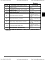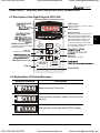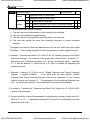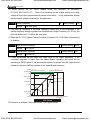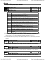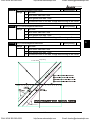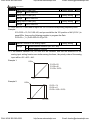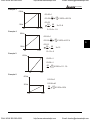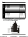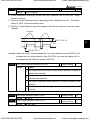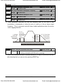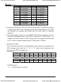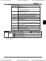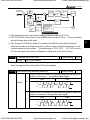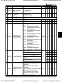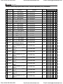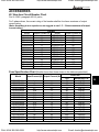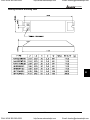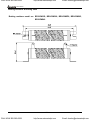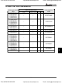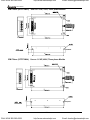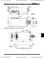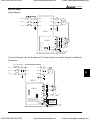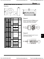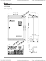
1
CALL NOW 800-985-6929
http://www.automatedpt.com
Email: [email protected]
VFD-V Series
Preface
Thank you for choosing DELTA’s high-performance VFD-V Series. VFD-V Series
are manufactured by adopting high-quality components, material and incorporating the
latest microprocessor technology available.
Getting Started
This manual will be helpful in the installation, parameter setting, troubleshooting, and daily
maintenance of the AC motor drives. To guarantee safe operation of the equipment, read
the following safety guidelines before connecting power to the AC drives. Keep this
operating manual handy and distribute to all users for reference.
!
WARNING
!
Always read this manual thoroughly before using VFD-V series AC Motor Drives.
!
DANGER! AC input power must be disconnected before any maintenance. Do not
connect or disconnect wires and connectors while power is applied to the circuit.
Maintenance must be performed by qualified technicians.
!
CAUTION! There are highly sensitive MOS components on the printed circuit boards.
These components are especially sensitive to static electricity. To avoid damage to
these components, do not touch these components or the circuit boards with metal
objects or your bare hands.
!
DANGER! A charge may still remain in the DC-link capacitor with hazardous voltages
even if the power has been turned off. To avoid personal injury, please ensure that
power has turned off before operating AC drive and wait ten minutes for capacitors to
discharge to safe voltage levels.
!
CAUTION! Ground the VFD-V using the ground terminal. The grounding method must
comply with the laws of the country where the AC drive is to be installed. Refer to Basic
Wiring Diagram.
!
DANGER! The AC drive may be destroyed beyond repair if incorrect cables are
connected to the input/output terminals. Never connect the AC drive output terminals
U/T1, V/T2, and W/T3 directly to the AC main circuit power supply.
!
CAUTION! The final enclosures of the AC drive must comply with EN50178. (Live parts
shall be arranged in enclosures or located behind barriers that meet at least the
requirements of the Protective Type IP20. The top surface of the enclosures or barrier
that is easily accessible shall meet at least the requirements of the Protective Type
IP40). (VFD-V series corresponds with this regulation.)
CAUTION! Heat sink may heat up over 70oC (158oF), during the operation. Do not
touch the heat sink.
DELTA ELECTRONICS, INC. ALL RIGHTS RESERVED
CALL NOW 800-985-6929
http://www.automatedpt.com
Email: [email protected]
CALL NOW 800-985-6929
http://www.automatedpt.com
Email: [email protected]
VFD-V Series
CHAPTER 1 RECEIVING AND INSPECTION
1.1 Nameplate Information ...........................................................................................1 - 1
1.2 Model Explanation..................................................................................................1 - 1
1.3 Serial Number Explanation.....................................................................................1 - 2
CHAPTER 2 STORAGE AND INSTALLATION
2.1 Storage ...................................................................................................................2 - 1
2.2 Installation ..............................................................................................................2 - 2
CHAPTER 3 WIRING
3.1 Basic Wiring Diagram .............................................................................................3 - 2
3.2 External Wiring .......................................................................................................3 - 5
3.3 Main Circuit Terminal Explanations.........................................................................3 - 6
3.4 Control Terminal Explanations ................................................................................3 - 6
3.5 Component Explanations .......................................................................................3 - 8
3.6 Wiring Notice ..........................................................................................................3 - 1 4
CHAPTER 4 DIGITAL KEYPAD (VFD-PU05) OPERATION
4.1 Description of the Digital Keypad VFD-PU05 .........................................................4 - 1
4.2 Explanations of Display Messages .........................................................................4 - 1
4.3 Operation steps of the Digital Keypad VFD-PU05 ..................................................4 - 3
CHAPTER 5 DESCRIPTION OF PARAMETER SETTINGS
5.1 Group 0: System Parameter...................................................................................5 - 1
5.2 Group 1: Basic Parameter ......................................................................................5 - 1 3
5.3 Group 2: Digital Output/Input Parameter ................................................................5 - 1 8
5.4 Group 3: Analog Output/Input Parameter ...............................................................5 - 2 7
5.5 Group 4: Multi-Step Speed and Procedural Operation Parameter..........................5 - 3 5
DELTA ELECTRONICS, INC. ALL RIGHTS RESERVED
CALL NOW 800-985-6929
http://www.automatedpt.com
Email: [email protected]
CALL NOW 800-985-6929
http://www.automatedpt.com
Email: [email protected]
VFD-V Series
5.6 Group 5: Motor Modulation Parameter ...................................................................5 - 4 0
5.7 Group 6: Protection Parameter...............................................................................5 - 4 5
5.8 Group 7: Special Parameter ...................................................................................5 - 5 2
5.9 Group 8: High-Performance Parameter..................................................................5 - 5 8
5.10 Group 9: Communication Parameter ....................................................................5 - 6 2
5.11 Group 10: Speed Feedback Parameter ................................................................5 - 7 3
CHAPTER 6
MAINTENANCE AND INSPECTIONS.......................................................6 - 1
CHAPTER 7
TROUBLESHOOTING...............................................................................7 - 1
CHAPTER 8
PARAMETER SUMMARY.........................................................................8 - 1
APPENDIX A
SPECIFICATIONS ...................................................................................A - 1
APPENDIX B
ACCESSORIES .......................................................................................B - 1
B.1 Fuse Specification Chart ........................................................................................B - 1
B.2 Braking Resistors ...................................................................................................B - 3
B.3 AMD - EMI Filter Cross Reference .........................................................................B - 7
B.4 PG Card .................................................................................................................B - 1 3
B.5 Zero Phase Reactor ...............................................................................................B - 17
APPENDIX C
DIMENSIONS...........................................................................................C - 1
APPENDIX D
EC DECLARATION OF CONFORMITY ..................................................D - 1
DELTA ELECTRONICS, INC. ALL RIGHTS RESERVED
CALL NOW 800-985-6929
http://www.automatedpt.com
Email: [email protected]
CALL NOW 800-985-6929
http://www.automatedpt.com
Email: [email protected]
CALL NOW 800-985-6929
http://www.automatedpt.com
Email: [email protected]
CALL NOW 800-985-6929
http://www.automatedpt.com
Email: [email protected]
VFD-V Series
CHAPTER 1 RECEIVING AND INSPECTION
This VFD-V AC drive has gone through rigorous quality control tests at the factory before
shipment. After receiving the AC drive, please check for the following:
1
Receiving
Check to make sure that the package includes an AC drive, the User Manual, dust
covers and rubber bushings.
Inspect the unit to insure it was not damaged during shipment.
Make sure that the part number indicated on the nameplate corresponds with the part number
of your order.
1.1 Nameplate Information → Example for 5HP/3.7kW 230V 3-Phase
Model Type
Input Spec.
Output Spec.
Output freq.
Barcode
037V23A0T0010123
1.2 Model Explanation
VFD 037 V 23 A
Version Type
Input Voltage
23:230V 3-PHASE
43:460V 3-PHASE
VFD-V Series
Applicable Motor Capacity
Series Name
DELTA ELECTRONICS, INC. ALL RIGHTS RESERVED
CALL NOW 800-985-6929
007:1HP(0.75kW)
015:2HP(1.5kW)
022:3HP(2.2kW)
037:5HP(3.7kW)
055:7.5HP(5.5kW) 075:10HP(7.5kW)
110:15HP(11kW)
150:20HP(15kW)
185:25HP(18.5kW) 220:30HP(22kW)
300:40HP(30kW)
370:50HP(37kW)
450:60HP(45kW)
550: 75HP(55kW)
750:100HP(75kW)
1-1
http://www.automatedpt.com
Email: [email protected]
CALL NOW 800-985-6929
http://www.automatedpt.com
Email: [email protected]
VFD-V Series
1.3 Serial Number Explanation
037V23A0T 0 10 9999
Production Number
Production Week
Production Year
Production Factory
Production Model
230V 3-PHASE 5HP(3.7kW)
●Please contact the dealers immediately should any discrepancy occurred.
1-2
CALL NOW 800-985-6929
DELTA ELECTRONICS, INC. ALL RIGHTS RESERVED
http://www.automatedpt.com
Email: [email protected]
CALL NOW 800-985-6929
http://www.automatedpt.com
Email: [email protected]
VFD-V Series
CHAPTER 2 STORAGE AND INSTALLATION
2.1 Storage
The AC drive should be kept in the shipping carton before installation. In order to retain the
warranty coverage, the AC drive should be stored properly when it is not to be used for an
extended period of time.
2
Ambient Conditions:
Operation
Air Temperature: -10oC to +40oC (14oF to 104oF)
+50oC (122oF) without dust cover.
Atmosphere pressure: 86 to 106 kPa
Installation Site Altitude: below 1000m
Vibration: Maximum 9.80 m/s2 (1G) at less than 20Hz
Maximum 5.88 m/s2 (0.6G) at 20Hz to 50Hz
Storage
Temperature: -20oC to +65oC (-4oF to 149oF)
Relative Humidity: Less than 90%, no condensation allowed
Atmosphere pressure: 86 to 106 kPa
Transportation
Temperature: -20oC to +60oC (-4oF to 140oF)
Relative Humidity: Less than 90%, no condensation allowed
Atmosphere pressure: 86 to 106 kPa
Vibration: Maximum 9.80 m/s2 (1G) at less than 20Hz, Maximum 5.88
m/s2 (0.6G) at 20Hz to 50Hz
Pollution Degree
2: good for a factory type environment.
DELTA ELECTRONICS, INC. ALL RIGHTS RESERVED
CALL NOW 800-985-6929
2-1
http://www.automatedpt.com
Email: [email protected]
CALL NOW 800-985-6929
http://www.automatedpt.com
Email: [email protected]
VFD-V Series
2.2 Installation
CAUTION
The control, power supply and motor leads must be laid separately. They must not be
fed through the same cable conduit / trunking.
High voltage insulation test equipment must not be used on cables connected to the
drive.
Improper installation of the AC drive will greatly reduce its life.
following precautions when selecting a mounting location.
Be sure to observe the
Failure to observe these precautions may void the warranty!
Do not mount the AC drive near heat-radiating elements or in direct sunlight.
Do not install the AC drive in a place subjected to high temperature, high humidity,
excessive vibration, corrosive gases or liquids, or airborne dust or metallic particles.
Mount the AC drive vertically and do not restrict the air flow to the heat sink fins.
The AC drive generates heat. Allow sufficient space around the unit for heat dissipation.
120mm
Air Flow
50mm
FWD
REV
PROG
DATA
50mm
120mm
2-2
CALL NOW 800-985-6929
DELTA ELECTRONICS, INC. ALL RIGHTS RESERVED
http://www.automatedpt.com
Email: [email protected]
CALL NOW 800-985-6929
http://www.automatedpt.com
Email: [email protected]
VFD-V Series
CHAPTER 3 WIRING
DANGER
Hazardous Voltage
Before accessing the AC drive:
Disconnect all power to the AC drive.
Wait five minutes for DC bus capacitors discharge.
3
Any electrical or mechanical modification to this equipment without prior written
consent of Delta Electronics, Inc. will void all warranties and may result in a safety
hazard in addition to voiding the UL listing.
Short Circuit Withstand:
The rated voltage must be equal to or less than 240V (460V model is 480Volts) and the current
must be equal to or less than 5000A RMS. (the model of 51HP or above is 10000A RMS)
General Wiring Information
Applicable Codes
VFD-V AC drives (007V23/43A, 015V23/43A, 022V23/43A, 037V23/43A, 055V23/43A,
075V23/43A, 110V43B, 110V23/43A, 150V23/43A, 185V23/43A, 220V23/43A, 300V23/43A,
370V23/43A, 450V43A) are Underwriters Laboratories, Inc. (UL) and Canadian Underwriters
Laboratories (cUL) listed, and therefore comply with the requirements of the National Electrical
Code (NEC) and the Canadian Electrical Code (CEC).
Installation intended to meet the UL and cUL requirements must follow the instructions
provided in “Wiring Notes” as a minimum standard. Follow all local codes that exceed UL and
cUL requirements. Refer to the technical data label affixed to the AC drive and the motor
nameplate for electrical data.
The "Line Fuse Specification" in Appendix B, lists the recommended fuse part number for each
V-Series part number. These fuses (or equivalent) must be used on all installations where
compliance with U.L. standards is a required.
DELTA ELECTRONICS, INC. ALL RIGHTS RESERVED
CALL NOW 800-985-6929
3-1
http://www.automatedpt.com
Email: [email protected]
CALL NOW 800-985-6929
http://www.automatedpt.com
Email: [email protected]
VFD-V Series
3.1 Basic Wiring Diagram
For wiring of the inverter, it is divided into the main circuit and the control circuit. Users
could open the case cover, and could inspect the main circuit terminal and the control circuit
terminal; users connect the circuit in compliance with the following wiring method.
The following diagram is the standard wiring diagram for the VFD-V inverter.
Wiring Diagram 1
10HP(7.5kW) and below
DC choke
(optional)
Jumper
Fuse/NFB(None Fuse Breaker)
+1
R/L1
S/L2
T/L3
E
R/L1
S/L2
T/L3
Recommended Circuit
when power supply
is turned OFF by a
fault output
Factory Default:
SINK Mode
SA
MC
ON
OFF
FWD/STOP
REV/STOP
Sink
Sw1
Multi-step 1
Source
Please refer to wiring
of SINK mode and
SOURCE mode.
Factory
default
Multi-step 2
Multi-step 3
Multi-step 4
Multi-step 5
Multi-step 6
Digital Signal Common
* Don input voltage directly
to the above signals.
E
RB
RA
RB
+24V
FWD
REV
MI1
MI2
MI3
MI4
MI5
MI6
DCM
RC
MRA
MRC
MO1
MO2
Shield terminal
+10V
5K
MCM
AFM
AVI
2
1
4~20mA
-10~+10V
Analog Signal Common
Master Frequency
0 to 10V 47K
ACI
AUI
ACM
Main circuit (power) terminals
CALL NOW 800-985-6929
DCM
Photocoupler Common
Output Terminal
Multi-function Analog Output
Terminal
Factory default: Output
Frequency 0~ 10VDC/2mA
Analog Signal common
Digital Frequency Output
Terminal
Factory default: 1:1
Duty=50% 10VDC
Digital Signal Common
RS-485
Serial interface
1: +EV 2: GND 3: SG4: SG+ 5:NC
6: NC
Control circuit terminals
3-2
Factory setting:
Operation Indication
Multi-function Photocoupler
Output 48VDC 50mA
Factory default:
Driver-Ready Indication
E
DFM
Power supply
+10V 20mA
Please refer to ontrol
Terminal Explanation?
Factory default:
Frequency-Achieving Indication
ACM
3
IM
3~
W/T3
RC
MC
Motor
B2
U/T1
V/T2
Shielded leads & Cable
DELTA ELECTRONICS, INC. ALL RIGHTS RESERVED
http://www.automatedpt.com
Email: [email protected]
CALL NOW 800-985-6929
http://www.automatedpt.com
Email: [email protected]
VFD-V Series
Wiring Diagram 2
15HP(11kW) and above
DC chock
(optional)
Fuse/NFB(None Fuse Breaker)
+1
R/L1
S/L2
T/L3
E
R/L1
S/L2
T/L3
Recommended Circuit
when power supply
is turned OFF by a
fault output
Factory Default:
SINK Mode
SA
MC
ON
OFF
REV/STOP
Sw1
Multi-step 1
Source
Please refer to wiring
of SINK mode and
SOURCE mode.
Factory
default
Multi-step 2
Multi-step 3
Multi-step 4
Multi-step 5
Multi-step 6
Digital Signal Common
U/T1
V/T2
RB
RA
RB
+24V
FWD
REV
MI1
MI2
MI3
MI4
MI5
MI6
DCM
RC
MRA
MRC
MO1
Power supply
+10V 20mA
1
4~20mA
-10~+10V
MCM
AFM
Analog Signal Common
Main circuit (power) terminals
DELTA ELECTRONICS, INC. ALL RIGHTS RESERVED
CALL NOW 800-985-6929
E
DFM
Master Frequency
0 to 10V 47K
ACI
AUI
ACM
Factory setting:
Operation Indication
Multi-function Photocoupler
Output 48VDC 50mA
Factory default:
Driver-Ready Indication
AVI
2
Please refer to ontrol
Terminal Explanation?
Factory default:
Frequency-Achieving Indication
MO2
+10V
5K
3
E
ACM
3
IM
3~
W/T3
Shield terminal
* Don input voltage directly
to the above signals.
Motor
-(minus sign)
RC
MC
FWD/STOP
Sink
VFDB
Jumper
DCM
Control circuit terminals
Photocoupler Common
Output Terminal
Multi-function Analog Output
Terminal
Factory default: Output
Frequency 0~ 10VDC/2mA
Analog Signal common
Digital Frequency Output
Terminal
Factory default: 1:1
Duty=50% 10VDC
Digital Signal Common
RS-485
Serial interface
1: +EV 2: GND 3: SG4: SG+ 5:NC
6: NC
Shielded leads & Cable
3-3
http://www.automatedpt.com
Email: [email protected]
CALL NOW 800-985-6929
http://www.automatedpt.com
Email: [email protected]
VFD-V Series
Wiring of SINK mode and SOURCE mode
+24V
FWD
REV
MI1
MI2
MI3
MI4
FWD/STOP
REV/STOP
Multi-step 1
Multi-step 2
Multi-step 3
Multi-step 4
Multi-step 5
Multi-step 6
Digital Signal Common
MI5
MI6
DCM
Sink
Sw1
Source
+24V
FWD
REV
MI1
MI2
MI3
MI4
FWD/STOP
REV/STOP
Multi-step 1
Multi-step 2
Multi-step 3
Multi-step 4
Multi-step 5
Multi-step 6
Digital Signal Common
3-4
CALL NOW 800-985-6929
MI5
MI6
DCM
DELTA ELECTRONICS, INC. ALL RIGHTS RESERVED
http://www.automatedpt.com
Email: [email protected]
CALL NOW 800-985-6929
http://www.automatedpt.com
Email: [email protected]
VFD-V Series
3.2 External Wiring
Items
Explanations
Please follow the specific power
Power
supply requirement shown in
supply
APPENDIX-A.
There may be inrush current during
Fuse/NFB power up. Please check the chart of
APPENDIX B and select the correct
(Optional) fuse with rated current. NFB is
optional.
Power Supply
FUSE/NFB
Magnetic
contactor
Please do not use a Magnetic
Magnetic
contactor as the I/O switch of the AC
contactor
drive, this will reduce the operating
(Optional)
life cycle of the AC drive.
Input AC
Line Reactor
Zero-phase
Reactor
EMI Filter
R/L1
S/L2
T/L3
+1
+2/B1
B2
U/T1
V/T2
Input AC
Line
Reactor
(Optional)
DC
Choke
Braking
Resistor
W/T3
Zero-phase
Reactor
Output AC
Line Reactor
Zero-phase
Reactor
(Ferrite
Core
Common
Choke)
(Optional)
EMI filter
(Optional)
In order to improve the input power
factor, reduces harmonics and
protection from AC line
disturbances. (Surge, switching
spike, power flick, etc.) AC line
reactor should be installed when the
power supply capacity is 500kVA or
more and exceeds 6 times of the
inverter capacity, or the wiring
distance within 10m.
Zero phase reactors are used to
reduce radio noise specify when the
audio equipments installed near the
inverter. Good effective for noise
reduction on both the input and
output sides. Attenuation quality is
good in a wide range from AM band
to 10Mhz. Appendix B for specifies
zero phase reactors. (RF220X00A)
To reduce the electromagnetic
interference. Please refer to
Appendix B for detail.
Used to reduce stopping time of the
Braking
motor. Please refer to the chart on
Resistor
Appendix B for specific Braking
(Optional)
Resistors.
Motor
Output AC
Line
Reactor
(Optional)
DELTA ELECTRONICS, INC. ALL RIGHTS RESERVED
CALL NOW 800-985-6929
3
Motor surge voltage amplitudes
depending on the motor cable
length. For long motor cable
application, it is necessary installed
on the inverter output side.
3-5
http://www.automatedpt.com
Email: [email protected]
CALL NOW 800-985-6929
http://www.automatedpt.com
Email: [email protected]
VFD-V Series
3.3 Main Circuit Terminal Explanations
Terminal Symbol
R/L1, S/L2, T/L3
Content Explanation
Input terminals for business-used power supply
U/T1, V/T2, W/T3 Output terminals for the AC motor drivers (at the side of the motor)
Power-improved continuing terminals of the DC reactor; disconnect
+1~+2/B1
the short-circuit piece when the device is installed
Connecting terminals of the braking resistor; purchase and install
+2/B1~B2
these devices according to the selection chart
+2/B1~
Continuing terminals of the braking module (the VFDB series)
Ground terminals, please have these terminals grounded following
the third-type grounding of 230V series and the special grounding of
460V series within the electrician regulations
3.4 Control Terminal Explanations
Terminal
Explanation on the Terminal Function
Symbol
FWD FWD RUN-STOP command
REV REV RUN-STOP command
MI1
Multi-function input selection 1 (3-wire
STOP-designated terminal)
MI2
Multi-function input selection 2
MI3
Multi-function input selection 3
MI4
Multi-function input selection 4
MI5
Multi-function input selection 5
MI6
Multi-function input selection 6 (TRG-designated
terminal)
DFM
Digital frequency signal output
+24V
DCM
RA
RB
RC
MRA
MRC
MO1
Factory Setting
Multi-step 1 command
Multi-step 2 command
Multi-step 3 command
Multi-step 4 command
Abnormal reset command
EF
1:1
+24V 20mA
Digital control signal – the common end
Digital control signal – the common end
Multi-function relay output contact (NO a)
Resistive Load
Multi-function relay output contact (NC b)
5A(N.O.)/3A(N.C.) 240VAC
Multi-function relay output contact
5A(N.O.)/3A(N.C.) 24VDC
Multi-function relay output contact (NO a)
Multi-function relay output contact – the common Inductive Load
end
1.5A(N.O.)/0.5A(N.C.)
240VAC
1.5A(N.O.)/0.5A(N.C.)
24VDC
Refer to Pr.02-11 to
Pr.02-12
Multi-function output terminal 1 (photo coupler)
Instruction during operation
3-6
CALL NOW 800-985-6929
DELTA ELECTRONICS, INC. ALL RIGHTS RESERVED
http://www.automatedpt.com
Email: [email protected]
CALL NOW 800-985-6929
http://www.automatedpt.com
Email: [email protected]
VFD-V Series
Terminal
Explanation on the Terminal Function
Symbol
MO2 Multi-function output terminal 2 (photo coupler)
(Max 48VDC 50mA)
MO3 Multi-function output terminal 3 (photo coupler)
(Max 48VDC 50mA)
MCM Multi-function output terminal – the common end
+10V
Auxiliary reference power
Factory Setting
Set up the frequency
attained
Driver ready
Max 48VDC 50mA
+10V 20mA
AVI
Analog voltage frequency command
ACI
Analog current frequency command
AUI
Auxiliary analog voltage frequency command
AFM
Multi-function analog voltage output
ACM
Analog control signal – the common end
The greatest operation
frequency corresponding to
0~+10V
The greatest operation
frequency corresponding to
4~20mA
The greatest operation
frequency corresponding to
-10~+10V
The greatest operation
frequency corresponding to
-10~10V
3
* Analog control signal wire specification: 18 AWG (0.8 mm2), cover the isolation
twisted wire.
DELTA ELECTRONICS, INC. ALL RIGHTS RESERVED
CALL NOW 800-985-6929
3-7
http://www.automatedpt.com
Email: [email protected]
CALL NOW 800-985-6929
http://www.automatedpt.com
Email: [email protected]
VFD-V Series
3.5 Component Explanations
1 HP to 5 HP (VFD007V23A/43A, VFD015V23A/43A, VFD022V23A/43A, VFD037V23A/43A)
+1 +2 B1
-
B2
U/T1 V/T2 W/T3
Screw Torque :
18Kgf-cm
Wire Gauge :
18~10AWG
R/L1 S/L2 T/L3
Control Terminal
Torque: 8Kgf-cm (6.9 in-lbf)
Wire: 22-14 AWG
Power Terminal
Torque: 18 kgf-cm (15.6 in-lbf)
Wire Gauge: 18-10 AWG
Wire Type: Stranded Copper only, 75°C
3-8
CALL NOW 800-985-6929
DELTA ELECTRONICS, INC. ALL RIGHTS RESERVED
http://www.automatedpt.com
Email: [email protected]
CALL NOW 800-985-6929
http://www.automatedpt.com
Email: [email protected]
VFD-V Series
7.5 HP to 15 HP (VFD055V23A/43A, VFD075V23A/43A, VFD110V43B)
3
POWER
IM
3
MOTOR
Control Terminal
Torque: 8Kgf-cm (6.9 in-lbf)
Wire: 22-14 AWG
Power Terminal
Torque: 30 kgf-cm (26 in-lbf)
Wire Gauge: 12-8 AWG
Wire Type: Stranded Copper only, 75°C
Note: If wiring of the terminal utilizes the wire with a 6AWG-diameter, it is thus
necessary to use the Recongnized Ring Terminal to conduct a proper wiring.
DELTA ELECTRONICS, INC. ALL RIGHTS RESERVED
CALL NOW 800-985-6929
3-9
http://www.automatedpt.com
Email: [email protected]
CALL NOW 800-985-6929
http://www.automatedpt.com
Email: [email protected]
VFD-V Series
15HP to 30HP (VFD110V23A/43A, VFD150V23A/43A, VFD185V23A/43A,
VFD220V23A/43A)
R/L1 S/L2 T/L3 +1
POWER
+2
DC (+)
-
DC ( - )
V/T2 W/T3
IM
3
MOTOR
Control Terminal
Torque: 8Kgf-cm (6.9 in-lbf)
Wire: 22-14 AWG
Power Terminal
Torque: 30 kgf-cm (26 in-lbf)
Wire Gauge: 8-2 AWG
Wire Type: Stranded Copper only, 75°C
NOTE: If wiring of the terminal of VFD220V23A utilizes the wire with a 1AWG-diameter, it
is thus necessary to use the Recognized Ring Terminal to conduct a proper
wiring.
3-10
CALL NOW 800-985-6929
DELTA ELECTRONICS, INC. ALL RIGHTS RESERVED
http://www.automatedpt.com
Email: [email protected]
CALL NOW 800-985-6929
http://www.automatedpt.com
Email: [email protected]
VFD-V Series
40 to 50 HP 230V (VFD300V23A, VFD370V23A)
3
POWER
ALARM
CHARGE
R/L1 S/L2 T/L3
POWER
+1
+2
Screw Torque:
200kgf-cm (173in-lbf)
U/T1 V/T2 W/T3
IM
3
MOTOR
Control Terminal
Torque: 8Kgf-cm (6.9 in-lbf)
Wire: 22-14 AWG
Power Terminal
Torque: 200 kgf-cm (173.6 in-lbf)
Wire Gauge: 1/0 – 4/0 AWG
Wire Type: Stranded Copper only, 75°C
DELTA ELECTRONICS, INC. ALL RIGHTS RESERVED
CALL NOW 800-985-6929
3-11
http://www.automatedpt.com
Email: [email protected]
CALL NOW 800-985-6929
http://www.automatedpt.com
Email: [email protected]
VFD-V Series
40HP to 60HP 460V (VFD300V43A, VFD370V43A, VFD450V43A)
POWER
ALARM
CHARGE
R/L1 S/L2 T/L3
+1
+2
-
POWER
U/T1 V/T2 2/T3
IM
3
MOTOR
Control Terminal
Torque: 8Kgf-cm (6.9 in-lbf)
Wire: 22-14 AWG
Power Terminal
Torque: 57 kgf-cm (49.5 in-lbf)
Wire Gauge: 4-2 AWG
Wire Type: Stranded Copper only, 75°C
3-12
CALL NOW 800-985-6929
DELTA ELECTRONICS, INC. ALL RIGHTS RESERVED
http://www.automatedpt.com
Email: [email protected]
CALL NOW 800-985-6929
http://www.automatedpt.com
Email: [email protected]
VFD-V Series
75-100 HP 460V (VFD550V43A, VFD750V43A)
3
R/L1 S/L2 T/L3
POWER
+1
+2
S c rew T orque:
200k gf-cm
U/T1 V/T2 W/T3
MOT OR
Control Terminal
Torque: 8Kgf-cm (6.9 in-lbf)
Wire: 22-14 AWG
Power Terminal
Torque: 200 kgf-cm (173.6 in-lbf)
Wire Gauge: 1/0 – 4/0 AWG
Wire Type: Stranded Copper only, 75°C
DELTA ELECTRONICS, INC. ALL RIGHTS RESERVED
CALL NOW 800-985-6929
3-13
http://www.automatedpt.com
Email: [email protected]
CALL NOW 800-985-6929
http://www.automatedpt.com
Email: [email protected]
VFD-V Series
3.6 Wiring Notice
1. There are corresponding ring terminals which will be included with each unit (15-30HP),
and please use the proper crimping tool by KST INC. P/N: KST-HDC38A for securing
the conductor.
2. When wiring up, and that the wiring route specifications are settled, please conduct the
wiring following the electrician regulations.
3. The connection between the three-phase AC input power and the main circuit terminal
R/L1, S/L2, T/L3 has to set up a none-fusing switch in between. The best is to series
connect with an electro-magnetic contactor (MC) so as to cut off the power supply at the
same time when the inverter protection function acts. (The two ends of the
electro-magnetic contactor should have the R-C Varistor).
4. There is no phase-order differentiation in the input power R/L1, S/L2, T/L3 and users
could connect with either one of use.
5. The ground terminal E is grounded with the third-type grounding method (with the
grounding impedance under 100Ω).
6. The grounding wire of the inverter could not be grounded at the same time with
machinery with grand current loading, like that of the electric soldering machine and of
the motor with grand horsepower; they have to be grounded individually.
7. The shorter the ground wire, the better it is.
8. When several inverters are grounded at the same time, be sure not to make it into a
ground circuit. Please refer to the following diagram:
FWD RUN
9. If the output terminals U/T1, V/T2 and W/T3 of the inverter are connecting relatively to
the U, V, and W terminals of the motor, the FWD indicator located on the digital control
panel of the inverter will be lit, and that means the inverter is running forward, and the
rotation direction of the motor will be shown as the right hand side diagram above; if the
REV indicator is lit, it means that the inverter is running in reverse direction, and the
rotation direction will be of the opposite direction compared with the above diagram. If
users are not sure of whether the connection between output terminals U/T1, V/T2 and
W/T3 of the inverter is of one-to-one connection with U, V, and W terminals of the motor,
simply swap either two wires among the U, V, and W terminals of the motor for
correction if the inverter is running forward while the motor is running at reverse
direction.
3-14
CALL NOW 800-985-6929
DELTA ELECTRONICS, INC. ALL RIGHTS RESERVED
http://www.automatedpt.com
Email: [email protected]
CALL NOW 800-985-6929
http://www.automatedpt.com
Email: [email protected]
VFD-V Series
10. Be sure of the power voltage and the greatest current possible supplied.
11. When the “Digital Hand-held Programming Panel” is displayed, please do not
disconnect or dissemble any wiring.
12. No braking resistor is installed within the VFD-V inverter (selective purchasing item),
therefore, be sure to purchase and install the braking resistor if to be used on occasions
when the loading inertia is great or that it is of frequent start/stop.
13. Be sure not to connect the AC power with the terminals U/T1, V/T2 and W/T3 on the
power-generating side of the inverter.
14. Please tightly fasten the screws of the main circuit terminals so as to prevent sparks
generated due to the vibration and loosening of the screws.
15. Wiring of the main circuit and of the control circuit should be separated so as to prevent
erroneous actions. If the interlock connection is needed, please make it an
3
intersection of 90°.
16. If terminals U/T1, V/T2 and W/T3 on the power-generating side of the inverter is in need
of the noise wave-filter, it is then necessary to use the induction-type L-Varistor, but be
sure not to add in the phase-carrying capacitor or the L-C- and R-C-type wave filters.
17. Please use the separating wire as much as possible during control wiring, and be sure
not to expose the peeled-off separation net in front of the terminal to the external.
18. Please use the separating wire or tube as much as possible during power wiring, and
ground these two ends of the separating layer or tube to the ground.
19. If the installation site of the inverter is sensitive to interferences, please have the RFI
wave filters installed, and the nearer the inverter to the installation site, the better. In
addition, the lower the carrier wave frequency of, the less the interferences.
20. If the electric-leakage circuit breaker is installed in the inverter, it could serve as the
protection for the electric-leakage error, and as the prevention on the erroneous actions
of the electric-leakage circuit breaker; please select the sensor current above 200mA
with the action time of more than 0.1 second to have these actions accessible.
DELTA ELECTRONICS, INC. ALL RIGHTS RESERVED
CALL NOW 800-985-6929
3-15
http://www.automatedpt.com
Email: [email protected]
CALL NOW 800-985-6929
http://www.automatedpt.com
Email: [email protected]
CALL NOW 800-985-6929
http://www.automatedpt.com
Email: [email protected]
CALL NOW 800-985-6929
http://www.automatedpt.com
Email: [email protected]
VFD-V Series
CHAPTER 4 DIGITAL KEYPAD (VFD-PU05) OPERATION
4.1 Description of the Digital Keypad VFD-PU05
LED Display
Display frequency, current, voltage
and error, etc.
F
H
U
Part Number
VFD-PU05
EXT PU
MODE Selection key
Press this key to view different
operating values
JOG
PU
Status Display
Display the driver's current status
When "PU" lights, RUN/STOP is
controlled by PU05. When "PU" is
dark, RUN/STOP is set by 00-21.
When "EXT" lights, frequency
command and torque command
is set by 00-20. When "EXT" is dark,
it is controlled by PU05.
4
Left key
moves cursor to the left
Right key
Moves the cursor right
FWD/REV Direction key
RUN key
STOP
RESET
RUN
STOP/RESET
4.2 Explanations of Display Messages
Messages Displayed
Descriptions
Master frequency of the drive
Actual operation frequency output to the motor from
the drive
User-selected content (the side DC-BUS voltage)
DELTA ELECTRONICS, INC. ALL RIGHTS RESERVED
CALL NOW 800-985-6929
4-1
http://www.automatedpt.com
Email: [email protected]
CALL NOW 800-985-6929
http://www.automatedpt.com
Email: [email protected]
VFD-V Series
Messages Displayed
Descriptions
Output current
Parameter duplication function: press
PROG/DATA and hold still for about 2~3 seconds,
it will start blinking and will duplicate the parameter
to PU-05.
Press the “Up” or “Down” key to switch to the
“SAVE” function
Parameter duplication function: press
PROG/DATA and hold still for about 2~3 seconds,
it will start blinking and will write the parameter into
the drive.
Press the “Up” or “Down” key to switch to the
“READ” function
The specified parameter item
Value of the parameter content
If the “End” message is displayed (as shown in the
figure), for about 1 second, it is an indication that
the data has been accepted and saved to the
internal memory automatically.
Displayed when the preset data is not accepted or
that the value goes over the limit
4-2
CALL NOW 800-985-6929
DELTA ELECTRONICS, INC. ALL RIGHTS RESERVED
http://www.automatedpt.com
Email: [email protected]
CALL NOW 800-985-6929
http://www.automatedpt.com
Email: [email protected]
VFD-V Series
4.3 Operation steps of the Digital Keypad VFD-PU05
VFD-PU05 Operation Flow Chart
Or
XX
4
Press UP key to select
SAVE: save parameters
READ: copy parameters
Press PROG/DATA for
about 2 seconds or until
it is flashing, then save/copy
data from AC drive to PU05.
XX-XX
XXXXX
-ERR-
-ENDSucceed to
Write in
Cannot
write in
DELTA ELECTRONICS, INC. ALL RIGHTS RESERVED
CALL NOW 800-985-6929
4-3
http://www.automatedpt.com
Email: [email protected]
CALL NOW 800-985-6929
http://www.automatedpt.com
Email: [email protected]
CALL NOW 800-985-6929
http://www.automatedpt.com
Email: [email protected]
CALL NOW 800-985-6929
http://www.automatedpt.com
Email: [email protected]
VFD-V Series
CHAPTER 5 DESCRIPTION OF PARAMETER SETTINGS
5.1 Group 0: System Parameter
00-00 Identity Code
Settings
Read Only
Factory setting
Read Only
Based on the model type
00-01 Rated Current Display
Settings
Factory setting
Based on the model type
230V Series
Power [HP]
0.75 1.5
[1] [2]
2.2
[3]
3.7 5.5 7.5 11 15 18.5 22 30 37
[5] [7.5] [10] [15] [20] [25] [30] [40] [50]
Model Code
4
6
8
10
12
14
16
18
20
22
24
26
Rated Current of the
Fixed Torque
5
7.5
11
17
25
33
49
65
75
90 120 146
Rated Current of the
6.25 9.375 13.75 21.25 31.25 41.25 61.25 81.25 93.75 112.5 150 182.5
Variable Torque
The Greatest Carrier
Wave Frequency
15KHz
5
10KHz
460V Series 0.75 1.5 2.2 3.7 5.5 7.5 11 15 18.5 22 30 37
45 55 75
Power [HP] [1] [2] [3] [5] [7.5] [10] [15] [20] [25] [30] [40] [50] [60] [75] [100]
Model Code
5
7
9
11
13
15
17 19
21
23
25
27
29
31
Rated Current
of the Fixed
Torque
3
4.2
6
8.5
13
18
24 32
38
45
60
73
91
110 150
Rated Current
of the Variable
Torque
3.75
5.25
7.5
22.5
30
47.5
56.25
75
91.25
113.75
The Greatest
Carrier Wave
Frequency
10.625 16.25
40
15KHz
10KHz
137.5
33
187.5
6KHz
Pr. 00-00 and Pr. 00-01 offer the user the ability to verify the drive’s capacity and current
rating which has been preset by the factory.
Note 1: This parameter is read only.
Note 2: The factory setting is a constant torque rating. If a variable torque rating is desired,
please refer to Pr. 00-12.
DELTA ELECTRONICS, INC. ALL RIGHTS RESERVED
CALL NOW 800-985-6929
5-1
http://www.automatedpt.com
Email: [email protected]
CALL NOW 800-985-6929
http://www.automatedpt.com
Email: [email protected]
VFD-V Series
00-02 Parameter Reset
Settings
Bit
settings
Factory setting
10
Parameter reset (for 60Hz input)
9
Parameter reset (for 50Hz input)
0
20 1
Bit 0 1 Parameters are read only
Bit 1 1 Disable Frequency and Torque Command changes. 21 2
22 4
Bit 2 1 Keypad disable
This parameter offers several functions.
1) The user may reset all parameters to their original factory settings.
2) The user may disable the keypad function.
3) The user may lock the parameters and allow them to be read only.
4) The user may disable the drive from accepting frequency or torque command
changes.
Throughout this manual, there are parameters such as this one, which use a term called
Bit Setting. This is simply the ability to have one parameter conduct multiple functions.
Example 1: Assume the function of Pr. 00-02 is set for “Disable Frequency and Torque
Command changes.” By referring to the above chart, we know Bit 1 is equal to “2”,
because the hex to decimal conversion is (2 ^ the bit = the decimal value). Therefore
21 = 2, and the decimal “2”, should be set in Pr. 00-02 to disable the frequency and
torque commands.
Example 2: Assume Pr. 00-02 is set for “Disable Frequency and Torque Command
changes” + “Keypad Disabled”.
If we follow what we have learned, “Disable
Frequency and Torque Command changes” must be set to decimal “2”; and “Keypad
Disable” must be set to decimal “4”. The summation of the two decimal numbers gives
us 6. By entering the number 6 in the parameter, both functions are enabled.
A setting of 1 enables the “Parameters are Read Only” feature, but Pr. 00-00~00-23,
continue to be accessed.
If users would like to reset the parameters to original factory-settings, simply set the Pr.
00-02 to “9” or “10”. If a password was entered, this must first be decoded to allow the
parameters to be reset.
5-2
CALL NOW 800-985-6929
DELTA ELECTRONICS, INC. ALL RIGHTS RESERVED
http://www.automatedpt.com
Email: [email protected]
CALL NOW 800-985-6929
http://www.automatedpt.com
Email: [email protected]
VFD-V Series
00-03
Start-up Display of the Drive
Settings
a
Factory setting
0
0 F (Master frequency command)
1 H (Output frequency)
2 U (multi-function display of Pr. 00-04)
3 Output current
This parameter allows the start-up display to be customized. The display may still be
changed, but during each power on, the display will default to the setting in this
parameter.
00-04 Definitions of the Multi-Function Display
a Factory setting
0
Settings
0
2
4
6
8
10
12
14
16
18
20
output voltage
voltage command
Speed command for the Process
Control Operation step
Remaining number of times for the
“restart after fault” feature
torque loading
Power factor angle (0~180 degrees)
Output power (Kva)
IGBT module temperature
Digital terminal input status
PID feedback value
the d axis voltage (Vector only)
22 Overload accumulated time
24
26
28
30
32
34
36
38
40
42
Execution time of the multi-step
speed
over-torque accumulated time
Compensated voltage
Running number of Encoder
(Channel 1)
Remaining pulses to reach position
control (home position)
The output AC voltage upon a fault
The current value upon a fault
day (power-up time)
The upper bound frequency value
Stall level limitation
DELTA ELECTRONICS, INC. ALL RIGHTS RESERVED
CALL NOW 800-985-6929
1 DC-BUS voltage
3 multi-step speed
Time remaining for the Process Control
5
Operation step
5
7 counter value
9
11
13
15
17
19
21
power factor ±1.000
Output power (Kw)
Motor speed (rpm)
Braking resistor temperature
PID output command
the q axis voltage (V/F and vector)
Magnetic flux
Electronic thermal relay accumulated
23
time
25 quiescence stage
27 DC braking time
29 Slip compensation frequency
31 PG position (position control)
33 DC voltage upon a fault
35
37
39
41
43
The output frequency upon a fault
the frequency command upon a fault
hour, minute
Over-torque level
Torque compensation gain
5-3
http://www.automatedpt.com
Email: [email protected]
CALL NOW 800-985-6929
http://www.automatedpt.com
Email: [email protected]
VFD-V Series
44
46
51
53
60
84
86
torque limit (Pr. 06-12)
Frequency of Encoder (Channel 1)
AVI input voltage
AUI input voltage
Input state of digital terminals
Input frequency of pulse (Channel 2)
OL3 timer
45
49
52
55
61
85
the q axis current (V/F and vector)
PID error value
ACI input current
Auxiliary frequency value
Output state of digital terminals
Input position of pulse (Channel 2)
This parameter defines the display content the User Defined setting. The User Defined
setting may be displayed upon power up (Pr. 00-03) or by pressing the Mode key on the
keypad and scrolling until the “U” is illuminated.
00-05 User-Defined Coefficient Setting
Settings
a Factory setting
4 digit
0-3: the number of the decimal places
3-0 digit
40~9999
0
This parameter allows the user to define a special value relative to the output frequency.
4th digit: Setting of the decimal places; 0 means that there is no decimal place and 3
stands for three decimal places.
3~0 digit: The actual value the maximum output frequency should correspond to.
Example: To display rpm’s for a 4-pole 60Hz motor with a base speed 1800rpm and no
slip, Pr 00-05 must be set as follows.
Set the 4th bit = 0, 3rd bit = 1, 2nd bit = 8, 1st bit = 0, 0 bit = 0.
The result of setting 01800 in Pr. 00-05 determines the value at 60Hz (Maximum Output
Frequency).
After this parameter is set, all functions relative to the frequency (except for the V/F
Curve frequency parameters) will automatically be changed to an RPM sale. RPM,
instead of Hz, will now be the unit for the keypad, and thus, if it is displayed as 60.00
before the setup, it will now display 1800 after the setup. Other parameters such as the
multi-step speed and JOG will be automatically changed also.
00-06 Software Version
Settings
Read-only
00-07 Password Input
Settings
a Factory setting 0
0~9999
00-08 Password Setting
Settings
a Factory setting 0
0~9999
5-4
CALL NOW 800-985-6929
DELTA ELECTRONICS, INC. ALL RIGHTS RESERVED
http://www.automatedpt.com
Email: [email protected]
CALL NOW 800-985-6929
http://www.automatedpt.com
Email: [email protected]
VFD-V Series
Pr. 00-07: This parameter allows the user to input their password and disable the
parameter lockout. An incorrect password may be entered 3 times and then a “Pcode”
will flash on the display, alerting the user the password is incorrect. The drive must be
powered off and then powered on again to clear the Pcode display.
Pr. 00-08: This parameter allows the user to input their password to lock out the
parameters from further changes.
To enter a password, the same password must be input twice within two minutes. To
verify the password was entered correctly, display the content of Pr. 00-08. If the
content is “1”, the password is entered. If the content is “0”, no password is entered.
To permanently disable the password. Enter the password in Pr. 00-07, then enter 0
into Pr. 00-08 twice within two minutes.
5
To re-activate the password, either enter an incorrect password into Pr. 00-07 or power
down and then re apply power to the AC drive.
00-09 Frequency and the Operation Method of PU05
Settings
Bit 0
a Factory setting
0 Frequency via the up/down keys
00000
0
0
1
Bit 1
Frequency command enabled after pressing the 2
data/prog key
0 PU05&RS485 frequency memorized
1 PU05&RS485 frequency not memorized
Bit 2
0 Up/down pin frequency memorized
1 Up/down pin frequency not memorized
Bit 3
0 FWD/REV direction memorized
1 FWD/REV direction not memorized
Bit 4
0 Parameter memorized
1 Parameter not memorized
21
22
23
24
1
0
2
0
4
0
8
0
16
This parameter allows the user to define the PU05 function. It also allows the user to
determine if the drive retains the direction and speed command after power has been
removed.
Pr. 00-09 = Bit 4 Bit 3 Bit 2 Bit 1 Bit 0 = xxxxx
Bit0 = This setting determines if it is necessary to press the PROG/DATA key first, to
enable the frequency/torque commands via up/down keys on the PU05.
DELTA ELECTRONICS, INC. ALL RIGHTS RESERVED
CALL NOW 800-985-6929
5-5
http://www.automatedpt.com
Email: [email protected]
CALL NOW 800-985-6929
http://www.automatedpt.com
Email: [email protected]
VFD-V Series
Bit1 = This setting allows the frequency/torque commands of PU05 and RS485 to either
be retained or forgotten after power has been removed.
Bit2 = This setting allows the frequency/torque commands of the UP/DOWN external
terminals to either be retained or forgotten after power has been removed.
Bit3 = This setting allows the FWD/REV direction to either be retained or forgotten after
power has been removed.
Bit4 = This parameter does not have to be memorized into EEPROM; its original value
will be recovered after the power is turned back on.
Example: If the frequency is to be controlled by the UP/DOWN keys (bit 0 = 0) and the
frequency is to be retained after power off (bit 1 = 1) and the direction is also to
be retained (bit3=1) then Pr. 00-09 must be set to 01010.
00-10 Control Methods
Settings
Factory setting
0
0 V/F Control
1 V/F Control + PG
2 Vector Control (open loop)
3 Vector Control + PG (closed loop)
4 Torque Control
5 Torque Control + PG
This parameter determines the control mode for the AC motor drive
0: V/F control: Drive will follow the V/F curve described by Pr. 01-00 to 01-08.
1: V/F control + PG: Drive will follow the V/F curve described by Pr. 01-00 to 01-08, but will
have more speed accuracy.
2: Vector Control: Enables Open Loop Vector control. To acquire the best results, it is
recommended to use the auto-tuning feature of the drive Pr. 05-00.
By using this
feature, 200% rated torque may be obtained at 0.5Hz. For more open loop vector
control, refer to group 5 parameters. While in Vector Control, Pr. 01-03 to 01-08 and Pr.
05-04 are not used.
3: Vector control + PG: Enables the Closed Loop Flux Vector Control. The Closed Loop
Flux Vector Control will offer the highest torque and speed accuracy control. 200%
torque at 0Hz and a 1:1000 turn down ratio. While in Vector Control, Pr. 01-03 to 01-08
and Pr. 05-04 are not used.
5-6
CALL NOW 800-985-6929
DELTA ELECTRONICS, INC. ALL RIGHTS RESERVED
http://www.automatedpt.com
Email: [email protected]
CALL NOW 800-985-6929
http://www.automatedpt.com
Email: [email protected]
VFD-V Series
4: Torque control: Enables Torque (current) Control. Torque control allows the user to run
the AC drive based on current instead of frequency.
5: Torque control + PG: Enables the Closed Loop Torque Control. This will increase the
torque accuracy throughout the speed range and disabled Pr. 05-04.
Note: PI values for PG (closed loop), vector control (open loop) and torque control are
determined by Pr. 05-21~05-25.
00-11 Forward Reverse transition in V/F mode
Settings
0
1
Follow Pr. 01-00 to
01-08 Settings
Follow Pr. 01-00 to
01-08 Settings
Factory setting
0
Do not skip the start-up frequency
Skip the start-up frequency
5
2 V/F1.5 power curve Do not skip the start-up frequency
3 V/F1.5 power curve Skip the start-up frequency
4 2 power curve
Do not skip the start-up frequency
5 2 power curve
Skip the start-up frequency
Frequency
FWD RUN
01-09
Startup
Frequency
Going through point 0
FWD RUN
REV RUN
REV RUN
FWD RUN
01-09
Startup
Frequency
STOP
V/F Mode bit=0
Not going through point 0
FWD RUN
Time
-01-09
REV RUN
REV RUN
V/F Mode bit=1
STOP
This parameter selects the transition mode between Forward and Reverse. By
skipping the start up frequency range, there will be a short time where the motor has not
flux and very little power. It is recommended for all non-horizontal movement to
choose “do not skip the start up frequency”.
DELTA ELECTRONICS, INC. ALL RIGHTS RESERVED
CALL NOW 800-985-6929
5-7
http://www.automatedpt.com
Email: [email protected]
CALL NOW 800-985-6929
http://www.automatedpt.com
Email: [email protected]
VFD-V Series
This parameter may also be used in Vector control to determine if the drive will skip the
zero point. If the drive skips the zero point, it will stop at the frequency determined by
Pr.01-09 and then start again in the opposite direction at Pr.01-09.
The Vector control
will generate its own V/F curve, therefore please select 0 or 1 for this parameter setting
when in Vector mode.
00-12 Constant Torque Operation Selection
Settings
a
Factory setting 0
0 oL (100%) Constant torque operation
1 oL (125%) Variable torque operation
When “1” is selected, the oL fault level is 125% of rated drive current. All other over load
ratings will not change, example: 150% of rated drive current for 60 sec.
00-13 Optimal Acceleration/Deceleration Setting
a Factory setting 0
Settings 0 Linear acceleration/deceleration (follow Pr. 01-12 to 01-21)
1 Auto acceleration (follow Pr. 07-09), Linear deceleration
2 Linear acceleration, Auto deceleration (follow Pr. 06-02)
3
Auto acceleration (follow Pr. 07-09), Auto deceleration (follow Pr.
06-02)
4
Linear acceleration/deceleration, but conduct the stall prevention
throughout the auto acceleration/deceleration function.
Optimal Acceleration/Deceleration settings could ease the drive’s vibration during loaded
starts and stops. Also if the detected torque is small, the processor will speed up the
acceleration time and reach the set frequency at the fastest and smoothest startup
possible. At deceleration, the processor will monitor regenerated voltage and
automatically stop the drive at the fastest and smoothest time possible. Pr. 07-09
(Maximum Current Level for Speed Search) is regarded as the target of the output
current upon acceleration.
00-14 Time Unit for Acceleration/Deceleration and S Curve
Settings
Factory setting
0
0 Unit: 0.01 sec
1 Unit: 0.1 sec
This parameter determines the time unit for the Acceleration/Deceleration setting. This
allows the user to choose either high resolution or long acceleration/deceleration times.
Refer to parameters (Pr. 01-12~01-19), the 1st to the 4th Acceleration/Deceleration Time,
(Pr. 01-20, 01-21) the JOG Acceleration/Deceleration Time and (Pr. 01-24~01-27) the S
Curve Acceleration/Deceleration Time.
5-8
CALL NOW 800-985-6929
DELTA ELECTRONICS, INC. ALL RIGHTS RESERVED
http://www.automatedpt.com
Email: [email protected]
CALL NOW 800-985-6929
http://www.automatedpt.com
Email: [email protected]
VFD-V Series
00-15 Carrier Frequency Upper Bound
Settings
a
Factory setting 10
a
Factory setting 10
a
Factory setting 3
0: soft pwm
1~15KHz
00-16 Carrier Frequency Lower Bound
Settings
1-15KHz (disabled during soft PWM)
00-17 Center Frequency of Soft pwm
Settings
1~7KHz
This parameter is utilized in setting the carrier frequency of the PWM output.
Carrier
Frequency
Electromagnetic
Noise
Interference,
Leakage Current
Heat
Dissipation
Maximum
Minimum
Minimum
Minimum
Maximum
Maximum
1kHz
5
8kHz
15kHz
00-15
PWM Carrier Frequency
00-16
01-00
Operation
Frequency
The PWM carrier frequency has a direct effect on the electromagnetic noise of the motor
and heat dissipation of the drive. Therefore, if the surrounding noise is greater than the
electromagnetic noises of the motor, it is suggested to lower the carrier frequency, to
decrease the temperature of the drive. Although a quiet operation may be achieved with
a higher carrier frequency, it is necessary to take into consideration the relative wiring
length between the motor and drive and the effect this high frequency may have on the
motor windings.
During SOFT PWM, the electromagnetic noises are less annoying at the same carrier
frequency for standard operation.
DELTA ELECTRONICS, INC. ALL RIGHTS RESERVED
CALL NOW 800-985-6929
5-9
http://www.automatedpt.com
Email: [email protected]
CALL NOW 800-985-6929
http://www.automatedpt.com
Email: [email protected]
VFD-V Series
If the carrier frequency’s lower bound (Pr. 00-16) > the carrier frequency’s upper bound
(Pr. 00-15), then the carrier frequency will be operated at the upper bound level.
00-18 Auto Voltage Regulation (AVR) Function
Settings
a Factory setting 0
0 AVR function enabled
1 AVR function disabled
2 AVR function disabled during deceleration
This parameter selects the AVR mode.
the motor.
AVR is used to regulate the output voltage to
The input voltage to the AC motor drive could range from AC180V-264V at, 50Hz/60Hz.
When this occurs, the output voltage to the motor will also vary from 180 to 264 unless
the AVR function is enabled. When enabled, the AVR function will limit the voltage to the
motor, based on Pr. 01-02.
00-19 Automatic Energy-Saving Operation
Settings
a Factory setting
00010
Bit 0 0 Disable automatic energy-saving operation
1 Enable automatic energy-saving operation
Bit 1 0 Maximum output voltage equals to the input power voltage
1
Maximum output voltage could be greater than the input power
voltage (over-modulation available)
When the Auto Energy-Saving function is enabled, the drive will operate with full voltage
during acceleration and deceleration. At constant speed the AC drive will calculate the
optimal output voltage value for the load. It is possible for the output voltage to be 25%
below Maximum Output Voltage during auto energy saving operation. This function
should not be used with variable loads or continuous rated output loads. During these
types of conditions, the operation will cycle on and off, giving poor energy saving results.
Output Voltage
100%
75%
The m aximum output voltage
reduction is 25%.
5-10
CALL NOW 800-985-6929
DELTA ELECTRONICS, INC. ALL RIGHTS RESERVED
http://www.automatedpt.com
Email: [email protected]
CALL NOW 800-985-6929
http://www.automatedpt.com
Email: [email protected]
VFD-V Series
00-20 Source of the Frequency Command
Settings
a Factory setting 0
0 The digital keypad
1 The RS485 communication input
2 The external analog input
3 The external up/down pins (multi-function input terminals)
4 The pg (encoder) input or clock
5 The RS485 and PU05 at the same time (dual source)
6 The clock and direction (set by 10-12)
This parameter determines the drive’s master frequency source and Master torque
source.
00-21 Source of the Operation Command
Settings
a Factory setting 0
5
0 The RS485 communication
1 The external terminal operation (2 wire or three wire)
2 The digital keypad operation
This parameter sets the drive’s operation command source, which may also be switched
via the PU key on the digital keypad. When the PU led on the keypad is illuminated the
Keypad has control over the drives operation.
00-22 Stop Methods
Settings
a Factory setting 0
0 Ramp to stop
1 Coast to stop
When a “STOP” command is received, the drive will follow the stop method programmed
this parameter.
Frequency
Output
Frequency
Output
Frequency
Time
Time
Operation
Command
RUN
STOP
DELTA ELECTRONICS, INC. ALL RIGHTS RESERVED
CALL NOW 800-985-6929
Operation
Command
RUN
Free running
to stop
STOP
5-11
http://www.automatedpt.com
Email: [email protected]
CALL NOW 800-985-6929
http://www.automatedpt.com
Email: [email protected]
VFD-V Series
Ramp to stop: The drive will ramp down from maximum output frequency (Pr. 01-00) to
minimum output frequency (Pr. 01-09) based on the deceleration time (Pr. 01-13).
Coast to stop: the drive will stop the output instantly upon a STOP command and the
motor will coast to stop according to its inertia (time unknown).
(1) In applications where the motor must stop after the drive is stopped, please select
“Ramp to Stop”. This is often a safety consideration.
(2) If the inertial load is large, it is recommended to set the drive for “Coast to Stop” to
eliminate nuisance Over Voltage faults.
00-23 Reverse Operation
Setting
a
Factory setting 0
0 REV enabled
1 REV disabled
2 FWD disabled
This parameter enables the AC drives ability to run in the Reverse Direction. It may be
used to prevent a motor from running in a direction that would consequently injure
humans or damage the equipment.
5-12
CALL NOW 800-985-6929
DELTA ELECTRONICS, INC. ALL RIGHTS RESERVED
http://www.automatedpt.com
Email: [email protected]
CALL NOW 800-985-6929
http://www.automatedpt.com
Email: [email protected]
VFD-V Series
5.2 Group 1: Basic Parameter
01-00 Maximum Output Frequency
Settings
Factory setting 60.00/50.00
50.0~400.00Hz
This parameter determines the drive’s maximum output frequency.
01-01 Maximum Voltage Frequency (Base Frequency)
Settings
Factory setting 60.00/50.00
0.00~400.00 Hz
This parameter must be set to the motor’s nameplate frequency rating.
01-02 Maximum Output Voltage
Settings
230V: 0.0~255.0V
Factory setting 220.0
460V: 0.0~510.0V
Factory setting 440.0
5
This parameter must be set to the motor’s nameplate voltage rating.
01-03 Upper Midpoint Output Frequency
Settings
Factory setting 0.50
0.00~400.00Hz
01-04 Upper Midpoint Output Voltage
Settings
230V: 0.0~255.0V
a
Factory setting 5.0
460V: 0.0~510.0V
a
Factory setting 10.0
01-05 Lower Midpoint Output Frequency
Settings
Factory setting 0.50
0.00~400.00Hz
01-06 Lower Midpoint Output Voltage
Settings
230V: 0.0~255.0V
a
Factory setting 5.0
460V: 0.0~510.0V
a
Factory setting 10.0
01-07 Minimum Output Frequency
Settings
Factory setting 0.00
0.00~400.00Hz
01-08 Minimum Output Voltage
Settings
230V: 0.0~255.0V
a
Factory setting 0.0
460V: 0.0~510.0V
a
Factory setting 0.0
Setting of the V/F curve figure is usually based upon the motor’s allowable loading
characteristics. Pay special attention to the motor’s heat dissipation, dynamic balance,
and bearing lubricity, if the loading characteristics exceed the loading limit of the motor.
DELTA ELECTRONICS, INC. ALL RIGHTS RESERVED
CALL NOW 800-985-6929
5-13
http://www.automatedpt.com
Email: [email protected]
CALL NOW 800-985-6929
http://www.automatedpt.com
Email: [email protected]
VFD-V Series
When setting the V/F curve, please follow this hierarchy for frequency:
01-01≥01-03≥01-05≥01-07.
There is no hierarchy for the voltage setting, but a high
voltage at low output frequencies may cause motor failure. At low frequencies, always
use the lowest voltage necessary for the application.
01-09 Startup Frequency
Settings
a Factory setting 0.50
0.00~400.00Hz
The Start-up Frequency is the initial frequency output upon a RUN command. If the
startup frequency setting is greater than the Maximum Output Frequency (Pr. 01-00), the
drive will default to Pr. 01-00 as the start point.
When the Pr. 07-12 (Speed-Tracing Function) is enabled, Pr. 01-09 (Start-up frequency)
is disabled.
01-10 Upper Bound Frequency
Settings
a Factory setting 100.0
0.0~110.0%
01-11 Lower Bound Frequency
Settings
a Factory setting 0.0
0.0~100.0%
These parameters set the upper and lower limits of the output frequency. If the
command frequency is lower than the Lower Bound frequency, the motor will be
operating at ZERO speed; if the command frequency is greater than the Upper Bound
frequency, the motor will then operate at the Upper Bound frequency.
Voltage
1st Voltage
01-02
01-11
Lower Bound Frequency
01-10
Upper Bound Frequency
Frequency output
ranges limitation
2nd Voltage
01-04
Regular V/F Curve
Special V/F Curve
3rd Voltage
01-06
4th Voltage
01-08
01-01
01-05
01-09
01-07
01-03
01-00
4th Freq.Startup Freq.3rd Freq. 2nd Freq. 1st Freq. Maximum Operation
Frequency
V/F Curve
This function is disabled if the Lower Bound > the Upper Bound.
5-14
CALL NOW 800-985-6929
DELTA ELECTRONICS, INC. ALL RIGHTS RESERVED
http://www.automatedpt.com
Email: [email protected]
CALL NOW 800-985-6929
http://www.automatedpt.com
Email: [email protected]
VFD-V Series
01-12 1st Acceleration Time
a Factory setting 10.00/60.00
st
01-13 1 Deceleration Time
a Factory setting 10.00/60.00
01-14 2nd Acceleration Time
a Factory setting 10.00/60.00
nd
01-15 2
Deceleration Time
a Factory setting 10.00/60.00
rd
01-16 3 Acceleration Time
a Factory setting 10.00/60.00
01-17 3rd Deceleration Time
a Factory setting 10.00/60.00
th
a Factory setting 10.00/60.00
th
01-19 4 Deceleration Time
a Factory setting 10.00/60.00
01-20 JOG Acceleration Time
a Factory setting 10.00/60.00
01-21 JOG Deceleration Time
a Factory setting 10.00/60.00
01-18 4 Acceleration Time
Settings
0.00~600.00 Sec/0.0~6000.0 Sec
The Acceleration Time the time needed for the drive to ramp from 0.0Hz to Maximum
Output Frequency (Pr. 01-00). The Deceleration Time is the time needed for the drive
to ramp down from Maximum Output Frequency (Pr. 01-00) to 0.00Hz.
The acceleration/deceleration times will be disabled if Pr. 00-13 (Auto
acceleration/deceleration Selection) is set for automatic operation.
Acceleration/Deceleration times 2 to 4 are enabled by using a multi-function terminal
(Pr.02-01 to 02-06) set to 8 or 9. Acceleration/Deceleration time 4 may also be
selected via Pr. 01-23.
Acceleration/Deceleration time 1 are the factory default for out-of-the-box operation.
The acceleration time has a direct effect on the rise of current upon a RUN command.
If the application load is large and the acceleration time is short (1 second) it is possible
5
the drive will fault with an “oc”. Similarly if the deceleration time is short (1 second) it is
possible the drive will fault with an “ov” due to motor regeneration.
DELTA ELECTRONICS, INC. ALL RIGHTS RESERVED
CALL NOW 800-985-6929
5-15
http://www.automatedpt.com
Email: [email protected]
CALL NOW 800-985-6929
http://www.automatedpt.com
Email: [email protected]
VFD-V Series
01-00
Maximum
Operation Frequency
Set Point of
the Operation
Frequency
Time
01-12
01-16
01-20
01-14
01-18
01-13
01-16
01-21
01-15
01-19
Definition of the Acceleration/Deceleration Time
01-22 JOG Frequency
a Factory setting 6.00
Settings 0.00Hz~400.00Hz
This parameter determines the Jog frequency.
The Jog function may be selected by
the JOG key on the PU05 keypad or the external I/O terminals. When the drive is
operating under a RUN command, the JOG operation is disabled. Likewise, the drive
will not accept a RUN command while the JOG command is enabled.
01-23 1st/4th Acceleration/Deceleration Frequency
a
Factory setting 0.00
Settings 0.00Hz~400.00Hz
This parameter selects the frequency point for transition from acceleration/deceleration
time 1 to acceleration/deceleration time 4.
The transition from acceleration/deceleration time 1 to acceleration/deceleration time 4,
may also be enabled by the external terminals (Pr. 02-01 to 02-06). The external
terminal has priority over Pr. 01-23.
5-16
CALL NOW 800-985-6929
DELTA ELECTRONICS, INC. ALL RIGHTS RESERVED
http://www.automatedpt.com
Email: [email protected]
CALL NOW 800-985-6929
http://www.automatedpt.com
Email: [email protected]
VFD-V Series
Frequency
1st Acceleration
Time
01-23
1st/4th
Acceleration
/Deceleration
Freq.
1st Deceleration
Time
4th Deceleration
Time
4th Acceleration Time
1st/4th Acceleration/Deceleration Switching
01-24 S-Curve for Acceleration Departure Time
a
Factory setting
0.00
01-25 S-Curve for Acceleration Arrival Time
a
Factory setting
0.00
01-26 S-Curve for Deceleration Departure Time
a
Factory setting
0.00
01-27 S-Curve for Deceleration Arrival Time
a
Factory setting
0.00
5
Settings 0.00~25.00 Sec/0.0~250.0 Sec
This parameter determines the S curve strength. A large S curve time will give the
smoothest transition between speed changes. Please note the S curve settings
increase the actual acceleration/deceleration times as follows:
Actual acceleration time = [½(Pr.01-24) + ½(Pr.01-25) + Pr.01-12]
The S curve is disabled when Pr. 00-13 (Auto Acceleration/Deceleration Speed
Selection) is set to Auto or Pr 01-12 to 01-19 (acceleration/deceleration times) is set to
0.
Frequency 01-25
01-26
01-27
01-24
DELTA ELECTRONICS, INC. ALL RIGHTS RESERVED
CALL NOW 800-985-6929
TIME
5-17
http://www.automatedpt.com
Email: [email protected]
CALL NOW 800-985-6929
http://www.automatedpt.com
Email: [email protected]
VFD-V Series
01-28 Skip Frequency 1 (upper limit)
Factory setting
0.00
01-29 Skip Frequency 1 (lower limit)
Factory setting
0.00
01-30 Skip Frequency 2 (upper limit)
Factory setting
0.00
01-31 Skip Frequency 2 (lower limit)
Factory setting
0.00
01-32 Skip Frequency 3 (upper limit)
Factory setting
0.00
01-33 Skip Frequency 3 (lower limit)
Factory setting
0.00
Settings
0.00~400.00Hz
These parameters determine the skip frequencies of the AC drive.
Please use the following hierarchy when setting these parameters: Pr. 01-28 > Pr. 01-29 >
Pr. 01-30 > Pr. 01-31> Pr. 01-32 > Pr. 01-33. The Skip frequency will be disabled if this
rule is not followed.
The Skip Frequencies are useful when a motor has vibration at a specific frequency
bandwidth. By skipping this frequency, the vibration will be avoided.
5-18
CALL NOW 800-985-6929
DELTA ELECTRONICS, INC. ALL RIGHTS RESERVED
http://www.automatedpt.com
Email: [email protected]
CALL NOW 800-985-6929
http://www.automatedpt.com
Email: [email protected]
VFD-V Series
5.3 Group 2: Digital Output/Input Parameter
02-00 2-Wire/3-Wire Operation Control
Factory setting 0
0 FWD/STOP, REV/STOP
Settings
1 FWD/STOP, REV/STOP (Line Start Lockout)
2 RUN/STOP, REV/FWD
3 RUN/STOP, REV/FWD (Line Start Lockout)
4 3-wire (momentary push button)
5 3-wire (momentary push button and Line Start Lockout)
The VFD-V drive offers six types of external operation control.
Three of the six methods include a “Line Start Lockout” feature. When Line
start lock out is enabled, the drive will not recognize a RUN command upon
power up. The VFD-V must see the terminal state change from low to high.
This is a safety feature for applications where applying power does not
determine a RUN command.
5
The Line Start Lockout feature does not guarantee the motor will never start under this
condition.
It is possible the motor may be set in motion by a malfunctioning switch.
02-00
0, 1
2-wire operation control (1)
FWD/STOP
REV/STOP
2, 3
2-wire operation control (2)
RUN/STOP
REV/FWD
4, 5
3-wire operation control
Control Circuits of the External Terminal
FWD/STOP
FWD:("OPEN":STOP)
("CLOSE":FWD)
REV/STOP
REV:("OPEN": STOP)
("CLOSE": REV)
DCM
VFD-V
RUN/STOP
FWD:("OPEN":STOP)
("CLOSE":RUN)
FWD/REV
REV:("OPEN": FWD)
("CLOSE": REV)
DCM
VFD-V
STOP
RUN
FWD "CLOSE":RUN
EF/MI1 "OPEN":STOP
REV/FWD "OPEN": FWD
RUN/FWD
"CLOSE": REV
DCM
VFD-V
DELTA ELECTRONICS, INC. ALL RIGHTS RESERVED
CALL NOW 800-985-6929
5-19
http://www.automatedpt.com
Email: [email protected]
CALL NOW 800-985-6929
http://www.automatedpt.com
Email: [email protected]
VFD-V Series
02-01 Multi-Function Input Command 1 (MI1) (NOTE 1)
Factory setting 1
02-02 Multi-Function Input Command 2 (MI2)
Factory setting 2
02-03 Multi-Function Input Command 3 (MI3)
Factory setting 3
02-04 Multi-Function Input Command 4 (MI4)
Factory setting 4
02-05 Multi-Function Input Command 5 (MI5)
Factory setting 5
02-06 Multi-Function Input Command 6 (MI6) (NOTE 2)
Factory setting 10
Factory setting 0
Factory setting 0
02-23 Multi-Function Input Command 7
02-24 Multi-Function Input Command 8
Factory setting 0
Factory setting 0
02-25 Multi-Function Input Command 9
02-26 Multi-Function Input Command 10
Factory setting 0
Factory setting 0
02-27 Multi-Function Input Command 11
02-28 Multi-Function Input Command 12
Factory setting 0
Factory setting 0
02-29 Multi-Function Input Command 13
02-30 Multi-Function Input Command 14
Settings
0 to 44
This parameter selects the functions for each multi-function terminal.
Note 1: If Pr.02-00 is set to 3-wire operation control. Terminal MI1 is needed for the third
wire position. Therefore MI1 is not allowed for any other operation.
Note 2: Multi-Function Input Commands 7-14 are the extension terminals of 02-01-02-06.
There are 14 terminals but the terminals 7-14 are virtual terminals and you can set
the state of bit 8-15 of 02-10 to ON or OFF by PU05 or communication.
Full List of the Functions
Settings Functions
Explanations
0
No Function
1
Multi-step Speed Command 1
2
Multi-step Speed Command 2
3
4
5
6
15 step speeds could be conducted through the
digital statuses of the 4 terminals, and 17 in total if
Multi-step Speed Command 3
the master speed and JOG are included.
Multi-step Speed Command 4
Reset
After the error of the drive is eliminated, use this
terminal to reset the drive
JOG Command
JOG operation
5-20
CALL NOW 800-985-6929
DELTA ELECTRONICS, INC. ALL RIGHTS RESERVED
http://www.automatedpt.com
Email: [email protected]
CALL NOW 800-985-6929
http://www.automatedpt.com
Email: [email protected]
VFD-V Series
Settings Functions
Explanations
7
Acceleration/deceleration
Speed Inhibit
When the acceleration/deceleration speed
inhibition function is executed, the drive will stop
the acceleration/deceleration immediately; the
drive will go on with the acceleration/deceleration
from where it stopped earlier after this command is
removed
The 1st, 2nd acceleration or
deceleration time selection
9
The acceleration/deceleration time of the drive
could be selected from this function or the digital
statuses of the terminals; there are 4
The 3rd, 4th acceleration or
acceleration/deceleration speeds in total for
deceleration time selection
selection.
10
EF Input
11
Disable Vector(stop)
8
External fault input terminal
If the ON/OFF function of the terminal is
pre-determined, output of the drive will be cut off
immediately, and the motor will then be of the B.B.
status.
And once the ON/OFF function is
restored, the drive will then trace from the bottom
upward to catch up with its mutual rotation speed
with the same frequency before B.B., then speed
up to the pre-set frequency. Even if the motor is
of a complete stop after B.B., as long as the
ON/OFF status is restored, the speed-tracing
function could still be operated.
12
B.B. traces from the bottom
upward
13
B.B. traces from the top
downward
14
Cancel the setting of the optimal acceleration/deceleration time
15
Switch between drive settings Used in the vector control
1 and 2
16
Operation speed command
form AVI
17
Operation speed command
from ACI
18
Operation speed command
from AUI
19
Emergency Stop
20
Digital Up command
Refer to Pr. 02-07
DELTA ELECTRONICS, INC. ALL RIGHTS RESERVED
CALL NOW 800-985-6929
5
5-21
http://www.automatedpt.com
Email: [email protected]
CALL NOW 800-985-6929
http://www.automatedpt.com
Email: [email protected]
VFD-V Series
Settings Functions
Explanations
21
Digital Down Command
22
Auto procedural operation function disabled
23
Auto procedural operation suspended
24
PID function disabled
When this terminal is functioning, the currently
displayed counter value will be cleared and “0” is
then displayed; the drive could only accept the
trigger signals to keep counting upward after this
signal disappeared.
25
Clear counter
26
Input the counter value (multi-function input command 6)
27
FWD JOG command
28
REV JOG command
29
Braking Module Breakdown
Accommodating the braking module breakdown
output
30
Position Control
Use with PG03/PG04
31
PG feedback control function
disable
32
Torque/Speed Switch
33
EEPROM write function
disable
34
It is a zero speed command and it is valid during
running. It is used to improve the vibration by using
Zero speed is replaced by DC
DC mode at zero speed when AC drive is not
current control
matched with motor or parameter settings of motor
is not very well.
35
04-35,04-36 disable
36
Position control 2 (PG2 input)
37
Dwell function disable
38
Pause Stop
AC drive stops at this moment and it will run after
closing the function of this terminal.
P2P Position Control
It can be used to control the 8 default positions
when using with PG03/PG04. But sub-function will
be valid when d36 is set.
39
It can be used as position function of clock input
when using with CH2 of PG04.
5-22
CALL NOW 800-985-6929
DELTA ELECTRONICS, INC. ALL RIGHTS RESERVED
http://www.automatedpt.com
Email: [email protected]
CALL NOW 800-985-6929
http://www.automatedpt.com
Email: [email protected]
VFD-V Series
Settings Functions
Explanations
40
P2P Hold
P2P is pause. AC drive keeps outputting at this
moment. It will keep on unfinished jog after
terminal is closed.
41
FWD Home Search
In speed mode, it will do FWD home search
according to the setting of 10-09.
P2P FWD Limit
In P2P mode, it is used with FWD limit sensor.
When it reaches FWD limit during running, it will
stop free running.
P2P REV Limit
In P2P mode, it is used with REV limit sensor.
When it reaches REV limit during running, it will
stop free running.
REV Home Search
In speed mode, it will do REV home search
according to the setting of 10-09.
42
43
44
02-07 UP/DOWN Key Mode
Settings Bit 0
Bit 1
a Factory setting
5
00000
0 UP/DOWM following the acceleration/deceleration time
1
UP following the constant speed, and DOWN following the
deceleration time
0
UP following the acceleration time, and DOWN following the
constant speed
1 UP/DOWN following the constant speed
The maximum Up/Down acceleration/deceleration speed is 10.00Hz/Sec.
02-08 The Acceleration/Deceleration Speed of the
UP/DOWN Key with Constant Speed
Settings
0.01
a Factory setting
0.005
0.01~1.00Hz/msec
02-09 Digital Input Responding Time
Settings
a Factory setting
0.001~30.000 Sec
Function of this parameter is to delay or confirm the message of the digital input terminals;
the delayed time is the confirmation time, which will be helpful in preventing some
uncertain interferences that would consequently result in erroneous motions (except for
the counter input) in the input of the digital terminals (FWD, REV, and MI1~6), and under
this condition, confirmation for this parameter could be improved effectively, but the
responding time will be somewhat delayed.
DELTA ELECTRONICS, INC. ALL RIGHTS RESERVED
CALL NOW 800-985-6929
5-23
http://www.automatedpt.com
Email: [email protected]
CALL NOW 800-985-6929
http://www.automatedpt.com
Email: [email protected]
VFD-V Series
02-10 Digital Input Operation Direction
Settings
a Factory setting 0
0~65535
Bit 0~7 1 High active
This parameter determines the level of the input signal operation.
02-11 Multi-Function Output 1
RA, RB, RC (Relay 1)
a Factory setting
15
02-12 Multi-Function Output 2
MRA, MRC (Relay 2)
a Factory setting
1
02-13 Multi-Function Output 3
MO1
a Factory setting
2
02-14 Multi-Function Output 4
MO2
a Factory setting
13
Settings
0 to 72
Settings
Functions
Explanations
0
No Function
1
AC Drive Running
2
Operation Speed Attained 1 (both
directions)
3
Operation Speed Attained 2 (both
directions)
4
Pre-set speed attained 1 (both directions)
5
Pre-set speed attained 2 (forward only)
6
Pre-set speed attained 1 (both directions)
7
Pre-set speed attained 2 (forward
direction)
10
Zero speed
Drive output is below Min Frequency
11
Over-torque(oL2)
Please refer to 06-08
12
Base block (Pause)
13
Drive ready for use
AC drive has no faults
14
Low voltage alarm (LV)
Please refer to 06-00
15
Error indication
16
Drive operation mode
17
PCO Run
18
PCO suspended
19
1st step of PCO completed
20
PCO completed
There is an output from the AC drive
Output is on when the external terminals
have command and off if keypad or
RS485 have control.
5-24
CALL NOW 800-985-6929
DELTA ELECTRONICS, INC. ALL RIGHTS RESERVED
http://www.automatedpt.com
Email: [email protected]
CALL NOW 800-985-6929
http://www.automatedpt.com
Email: [email protected]
VFD-V Series
Settings
Functions
Explanations
21
Pre-set counter value attained
Please refer to 02-16
22
Desired counter value attained
Please refer to 02-17
23
Heat sink overheat warning
Please refer to 06-15
24
Operation frequency attained 1 (both
directions)
25
Operation frequency attained 2 (both
directions)
26
Pre-set frequency attained 1 (both
directions)
27
Pre-set frequency attained 2 (forward
only)
28
Pre-set frequency attained 1 (both
directions)
29
Pre-set frequency attained 2 (forward
only)
30
Software braking output
Please refer to 07-00
Position Achieved
In position mode, position point can
output a position achieved signal by
setting this parameter. At this moment,
AC drive achieves position and motor is
in holding state.
31
5
32~47 PCO Step Indication
Corresponds to the 0~15 step speeds
48~63 Multi-step Indication
Corresponds to the 0~15 step speeds
64
PG Fault
65
PG Stall
69
Over-torque(oL3)
70
Zero speed (STOP)
71
Position synchronization 1 (10-10)
72
Position synchronization 2 (10-23)
Please refer to 06-09
In position mode, you can output a
position synchronization signal by
setting d71, d72 (please refer to 10-10,
10-23)
02-15 Multi-Function Output Direction
Settings
a Factory setting 00000
0~15 (1 high)
This function uses the Bit setting method.
DELTA ELECTRONICS, INC. ALL RIGHTS RESERVED
CALL NOW 800-985-6929
5-25
http://www.automatedpt.com
Email: [email protected]
CALL NOW 800-985-6929
http://www.automatedpt.com
Email: [email protected]
VFD-V Series
Example: If Pr.02-10 is 1 (AC Drive running), and Relay 1 is set to N.O., then R1 close when
the drive has an output and will open when the drive has stopped.
Settings
Bit
content
Relay 1
03-07
Relay 2
03-08
MO1
03-09
MO2
03-10
0
0000
N.O.
N.O.
N.O.
N.O.
1
0001
N.O.
N.O.
N.O.
N.C.
2
0010
N.O.
N.O.
N.C.
N.O.
3
0011
N.O.
N.O.
N.C.
N.C.
4
0100
N.O.
N.C.
N.O.
N.O.
5
0101
N.O.
N.C.
N.O.
N.C.
6
0110
N.O.
N.C.
N.C.
N.O.
7
0111
N.O.
N.C.
N.C.
N.C.
8
1000
N.C.
N.O.
N.O.
N.O.
9
1001
N.C.
N.O.
N.O.
N.C.
10
1010
N.C.
N.O.
N.C.
N.O.
11
1011
N.C.
N.O.
N.C.
N.C.
12
1100
N.C.
N.C.
N.O.
N.O.
13
1101
N.C.
N.C.
N.O.
N.C.
14
1110
N.C.
N.C.
N.C.
N.O.
15
1111
N.C.
N.C.
N.C.
N.C.
Note: N.O. : normal open, N.C.: normal close
02-16 Counter Values Achieve the Pre-Set Values
Settings
a Factory setting 0
0~65500
The input contact of the counter could set the multi-function terminal MI6 (with the
designated terminal Pr. 02-06 as 26) as the trigger terminal, and when the counting is over
(which reaches the destination), the signals could select one among the multi-function
output terminals (with Pr. 02-10~02-13 set as 21) to be the motion contact.
02-17 Designated Counter Value Achieved
Settings
a
Factory setting 0
0~65500
When the counter value starts counting upward from 1 to the setting of this parameter, its
corresponding multi-function output terminal contact with the “arbitrary counting
achieves the output indication” function would start functioning. This parameter could
be utilized at the moment when the counting is almost to an end, and then, set the
output signal to enable the drive operating at a low speed till it stopped.
The Time-and-Order Diagram is shown as follows:
5-26
CALL NOW 800-985-6929
DELTA ELECTRONICS, INC. ALL RIGHTS RESERVED
http://www.automatedpt.com
Email: [email protected]
CALL NOW 800-985-6929
http://www.automatedpt.com
Email: [email protected]
VFD-V Series
0.5ms
Display
(Pr.00-04=07)
TRG
Counter Trigger
(Output signal)
Multi-function output terminal
Pr. 02-10~02-13
02-12=22
Desired Counter Value
Attained output
Preset Counter Value
Attained output
0.5ms
Trigger signal width
02-16=3
02-13=21
02-15=5
Diagram of the External Counter Terminal and the Arrival of the Counter Value
02-18 Digital Output Gain
Settings
a Factory setting
1
1~40
This parameter determines the signals of the drive’s digital output terminal (DFM-DCM)
and of the digital frequency output (pulse, work period = 50%). Output pulse per
second = output frequency × (Pr. 02-17)。
5
Setting of the multiple has a lot to do with the carrier frequency; the carrier frequency has
to be greater than “2 x maximum operation frequency x multiplying rate”.
02-19 Pre-set Arrival Frequency 1
Settings
a Factory setting 60.00/50.00
0.00~400.00Hz
02-20 Pre-set Arrival Frequency 1 Width
Settings
a Factory setting 2.00
0.00~400.00Hz
02-21 Pre-set Arrival Frequency 2
Settings
a Factory setting 60.00/50.00
0.00~400.00Hz
02-22 Pre-set Arrival Frequency 2 Width
Settings
a Factory setting 2.00
0.00~400.00Hz
Once the drive’s output speed (frequency) achieves the arbitrary designated (speed)
frequency, and that if the corresponding multi-function output terminal is set as 2~7 or
24~27 (Pr. 02-10~02-14), then the multi-function output terminal contact will be “closed”.
DELTA ELECTRONICS, INC. ALL RIGHTS RESERVED
CALL NOW 800-985-6929
5-27
http://www.automatedpt.com
Email: [email protected]
CALL NOW 800-985-6929
http://www.automatedpt.com
Email: [email protected]
VFD-V Series
5.4 Group 3: Analog Output/Input Parameter
03-00 Analog Input 1 (AVI)
a Factory setting
1
03-01 Analog Input 2 (ACI)
a Factory setting
0
03-02 Analog Input 3 (AUI)
a Factory setting
0
Settings
Function
0
no function (analog input disabled)
1
frequency/torque command (See Pr.00-10)
2
torque limitations (increase or decrease torque limit Pr. 06-12)
3
acceleration/deceleration time gain (increase or decrease time base)
4
upper bound frequency (increase or decrease Pr.01-10)
5
over-torque current level (increase or decrease Pr.06-07)
6
torque compensation gain (increase or decrease Pr.05-03 / 05-13)
7
over-current stall prevention level during operation(06-04)
8
torque compensation(Vector)
9
AVI auxiliary frequency (multiplication by the ratio of AVI)
10
ACI auxiliary frequency (multiplication by the ratio of ACI)
11
AUI auxiliary frequency (multiplication by the ratio of AUI)
12
PID offset
13
Auxiliary frequency of master frequency
The value (0~10V/4~20mA) of the setting 2 (torque limitations) corresponds to rated
output current 0~100% can be adjusted by analog input gain 03-09~03-11.
current stall level during running: when 03-00~03-02 is set to d7, the setting of 06-04 is
disable.
03-03 (AVI) Analog Input Bias 1
Settings
a Factory setting 0.00
-10.00~10.00V
This parameter determines the AVI voltage value that corresponds to 0Hz frequency.
03-04 (ACI) Analog Input Bias 2
Settings
a Factory setting 4.00
0.00~20.00mA
This parameter determines the ACI current value that corresponds to 0Hz frequency.
03-05 (AUI) Analog Input Bias 3
Settings
a Factory setting 0.00
-10.00~10.00V
This parameter determines the AUI voltage value that corresponds to 0Hz frequency.
5-28
CALL NOW 800-985-6929
DELTA ELECTRONICS, INC. ALL RIGHTS RESERVED
http://www.automatedpt.com
Email: [email protected]
CALL NOW 800-985-6929
http://www.automatedpt.com
Email: [email protected]
VFD-V Series
03-06 (AVI) Positive/Negative Bias Mode
Settings
a Factory setting 0
0
zero bias
1
value lower than bias = bias
2
value greater than bias = bias
3
the absolute value of the bias voltage while serving as the center
03-07 (ACI) Positive/Negative Bias Mode
Settings
a Factory setting 1
0
zero bias
1
value lower than bias = bias
2
value greater than bias = bias
3
the absolute value of the bias voltage while serving as the center
03-08 (AUI) Positive/Negative Bias Mode
Settings
a Factory setting 0
0
zero bias
1
value lower than bias = bias
2
value greater than bias = bias
3
the absolute value of the bias voltage while serving as the center
01-00=60Hz
5
Frequency
3
3
0
1
1
0
3
1
-10V -9 -8 -7 -6 -5 -4 -3 -2 -1
2
1
2
3
4
5
6
7
8
9 10V
2
0
Gain adjustment
DELTA ELECTRONICS, INC. ALL RIGHTS RESERVED
CALL NOW 800-985-6929
5-29
http://www.automatedpt.com
Email: [email protected]
CALL NOW 800-985-6929
http://www.automatedpt.com
Email: [email protected]
VFD-V Series
03-09 Analog Input 1 Gain (AVI)
Settings
a Factory setting
125.0
a Factory setting
100.0
-500.0~+500.0%
03-11 Analog Input 3 Gain (AUI)
Settings
100.0
-500.0~+500.0%
03-10 Analog Input 2 Gain (ACI)
Settings
a Factory setting
-500.0~+500.0%
Pr.03-09 to 03-11 are used to adjust the 10V or 20mA corresponding frequency value.
Example:
If Pr.03-00 = 10, Pr.01-00 =60, and you would like the 10V position of AVI (0-10V ) to
equal 60Hz, than use the following equation to program the Gain.
Pr.03-09 = ( 1+ (Pr.03-00/Pr.01-00))x 100
03-12 Addition Function of the Analog Inputs
Settings
a Factory setting
0
0 disable addition function (AVI, ACI, AUI)
1 enable addition function
If the addition between AVI, ACI and AUI are disabled, and that the selections on the
analog input setting function are similar among the three, the priority order of the analog
input will be: AVI > ACI > AUI.
Example 1:
60Hz
03-03=0V
03-06=d0
03-09=100%
0V
Example 2:
10V
60Hz
03-03=1V
03-06=d1
03-09=10/8=125%
1V
9V 10V
5-30
CALL NOW 800-985-6929
DELTA ELECTRONICS, INC. ALL RIGHTS RESERVED
http://www.automatedpt.com
Email: [email protected]
CALL NOW 800-985-6929
http://www.automatedpt.com
Email: [email protected]
VFD-V Series
Example 3:
60Hz
03-06=1
03-09=
Example 4:
9V 10V
60Hz
X=10.8
9-10.8=-1.8
03-06=1
03-09=
0V
60
X100%=83.3%
10
50
10
03-03
50 60
=
10
X
10Hz
Example 5:
60
X100%=92.5%
10
03-03
50 60
=
9
X
10Hz
0V
50
9
10V
5
X=12
10-12=-2
60Hz
03-03=1
03-06=1
60
9
1V
Example 6:
10V
60Hz
03-03=0
03-06=d0
30Hz
30
10
0V
60
X100%=50%
10
10V
DELTA ELECTRONICS, INC. ALL RIGHTS RESERVED
CALL NOW 800-985-6929
60
X100%=111.1%
10
5-31
http://www.automatedpt.com
Email: [email protected]
CALL NOW 800-985-6929
http://www.automatedpt.com
Email: [email protected]
VFD-V Series
Example 7:
60Hz
03-03=5
03-06=3
0V
Example 8:
5V
60
X100%=200%
10
120
20
10V
60Hz
03-03=10
03-06=0
03-09=-100%
10V
Example 9:
60Hz
FWD
03-03=5
03-06=d 0
0V
5V
REV
10V
60
X100%=200%
10
120
10
60Hz
Example 10:
60Hz
FWD
03-05=0
03-08=0
-10V
0V
REV
10V
60
X100%=100%
10
60Hz
5-32
CALL NOW 800-985-6929
120
20
DELTA ELECTRONICS, INC. ALL RIGHTS RESERVED
http://www.automatedpt.com
Email: [email protected]
CALL NOW 800-985-6929
http://www.automatedpt.com
Email: [email protected]
VFD-V Series
03-13 Analog Input Noise Filter
Settings
a Factory setting 0.10
0.00~2.00 Sec
Interferences commonly exist with analog signals, such as those entering AVI, ACI and AUI.
These interferences constantly affect the stability of analog control and using the Input
Noise Filter will create a more stable system.
If Pr. 03-13 is large, the control will be stable, yet the response to the input will be slow. If
Pr. 03-13 is small, the control may be unstable, yet the response to the input will fast.
03-14 Loss of the ACI signal
Settings
a Factory setting 0
0
disabled
1
continue operation at last known frequency
2
decelerate to a stop
3
stop immediately and display E.F.
5
This parameter determines the operation of the drive when the 4~20mA (ACI) signal is lost.
03-15 Analog Output Selection
Settings
a Factory setting 0
0-24
Full List of the Functions
Settings
Functions
Explanations
0
Output frequency
01-00=100%
1
Command frequency
01-00=100%
2
Speed
01-00=100%
3
Current
rated current of the inverter =100%
4
Output voltage
200V (400V) =100%
5
DC BUS voltage
400V (800V) =100%
6
Power factor
-1.000~1.000=100%
7
Power
rated power of the inverter =100%
8
Torque
full-load torque =100%
9
AVI
(0~10V=0~100%)
10
ACI
(0~20mA=0~100%)
11
AUI
(-10~10V=0~100%)
12
Torque current command
rated current of the inverter =100%
13
Torque current estimation
rated current of the inverter =100%
14
Exciting magnet current
command
rated current of the inverter =100%
15
Magnetic flux current
rated current of the inverter =100%
DELTA ELECTRONICS, INC. ALL RIGHTS RESERVED
CALL NOW 800-985-6929
5-33
http://www.automatedpt.com
Email: [email protected]
CALL NOW 800-985-6929
http://www.automatedpt.com
Email: [email protected]
VFD-V Series
Settings
Functions
Explanations
16
Q-axis voltage command
200V (400V) =100%
17
D-axis voltage command
200V (400V) =100%
18
Vector-controlled error
measures
01-00=100%
19
Vector-controlled PID
overall measures
01-00=100%
20
PID error measures
01-00= 100% (full-load torque = 100%: torque
control)
21
PID total measures
01-00= 100% (full-load torque = 100%: torque
control)
22
Torque command
full-load torque =100%
23
Pg frequency
01-00=100%
24
Voltage command
200V (400V) =100%
03-16 Analog Output Gain
Settings
a Factory setting 100.0
-900.0~900.0%
This parameter adjusts the voltage level of the analog output signal (AFM = Pr. 03-13).
The parameter sets the voltage range of the analog output signal at terminals AFM-ACM,
that corresponds with either the output frequency or the output current of the VFD.
AFM
AFM
GND
+
-
GND
+
Analog Frequency Meter
-
Analog Current Meter
The analog output voltage is directly proportional to the output frequency of the AC drive. With
the factory setting of 100%, the Maximum Output Frequency (Pr.01-00) of the AC drive
corresponds to +10VDC analog voltage output. (The actual voltage is about +10VDC, and can
be adjusted by Pr.03-16).
The analog output voltage is directly proportional to the output current of the AC drive. With the
factory setting of 100%, the 2.5 times rated current of the AC drive corresponds to +10VDC
analog voltage output. (The actual voltage is about +10VDC, and can be adjusted by Pr.
03-16)
Note: Voltmeter specification: The sourcing capability of the output is limited to 0.21mA.
Sourcing voltage: 10V. Output resistance: 47kΩ.
5-34
CALL NOW 800-985-6929
DELTA ELECTRONICS, INC. ALL RIGHTS RESERVED
http://www.automatedpt.com
Email: [email protected]
CALL NOW 800-985-6929
http://www.automatedpt.com
Email: [email protected]
VFD-V Series
If the meter reads full scale at a voltage less than 10 volts, then Pr.03-16 should be set
by the following formula:
Pr.03-16 = ((meter full scale voltage)/10) ×100%
For Example: When using the meter with full scale of 5 volts, adjust Pr.03-16 to 50%.
03-17 Analog Output Bias Voltage
Settings
a Factory setting
0.00
-10.00~10.00V
This parameter determines the output voltage value corresponding to 0Hz.
a Factory setting
03-18 Analog Output Value in REV Direction
Settings
0 absolute value in REV direction
1 output 0V in REV direction
2 output negative voltage in REV direction
10V
10V
03-18=0
-10V
5
10V
03-18=20
03-18=1
-10V
0
-10V
03-19 Reserved
DELTA ELECTRONICS, INC. ALL RIGHTS RESERVED
CALL NOW 800-985-6929
5-35
http://www.automatedpt.com
Email: [email protected]
CALL NOW 800-985-6929
http://www.automatedpt.com
Email: [email protected]
VFD-V Series
5.5 Group 04: Multi-Step Speed and Process Control Operation (PCO)
04-00 The 1st Step Speed
a Factory setting 0.00
nd
04-01 The 2 Step Speed
a Factory setting 0.00
04-02 The 3rd Step Speed
a Factory setting 0.00
th
a Factory setting 0.00
th
04-04 The 5 Step Speed
a Factory setting 0.00
04-05 The 6th Step Speed
a Factory setting 0.00
04-03 The 4 Step Speed
th
a Factory setting 0.00
th
a Factory setting 0.00
th
04-08 The 9 Step Speed
a Factory setting 0.00
04-09 The 10th Step Speed
a Factory setting 0.00
04-06 The 7 Step Speed
04-07 The 8 Step Speed
th
a Factory setting 0.00
th
04-11 The 12 Step Speed
a Factory setting 0.00
04-12 The 13th Step Speed
a Factory setting 0.00
04-10 The 11 Step Speed
th
a Factory setting 0.00
th
a Factory setting 0.00
04-13 The 14 Step Speed
04-14 The 15 Step Speed
Settings
0.00~400.00Hz
The multi-function input terminals (refer to Pr. 02-01 to 02-06) are used to select one of
the AC drive Multi-Step Speeds above. These speeds may also be used in conjunction
with Pr. 04-15 - 04-32 to run the process control operation.
04-07
Frequency
04-06
04-05
04-08
04-09
04-04
04-10
04-03
04-11
04-02
04-12
04-01
JOG Freq.
04-13 01-22
04-00
04-14
Master Speed
2 3 4 5 6 7 8 9 1011 12 131415
Run Signal
1st step speed
Multi-function Terminal
Pr.02-01 to Pr.02-06
(Mi1 to MI6 1)
2nd step speed
Multi-function Terminal
Pr.02-01 to Pr.02-06
(Mi1 to MI6 2)
3rd step speed
Multi-function Terminal
Pr.02-01 to Pr.02-06
(MI1 to MI6 3)
4th step speed
Multi-function Terminal
Pr.02-01 to Pr.02-06
(MI1 to MI6 4)
ON
OFF
ON
OFF
OFF
ON
ON
ON
ON
ON
ON
ON
ON
ON
ON
ON
ON
OFF
ON
OFF
ON
Jog Freq.
Multi-Step Speed via External Terminals
5-36
CALL NOW 800-985-6929
DELTA ELECTRONICS, INC. ALL RIGHTS RESERVED
http://www.automatedpt.com
Email: [email protected]
CALL NOW 800-985-6929
http://www.automatedpt.com
Email: [email protected]
VFD-V Series
04-15 Time Duration of the PCO Master Speed
a Factory setting
0
04-16 Time Duration of PCO Step 1
04-17 Time Duration of PCO Step 2
a Factory setting
0
a Factory setting
0
04-18 Time Duration of PCO Step 3
a Factory setting
0
04-19 Time Duration of PCO Step 4
a Factory setting
0
04-20 Time Duration of PCO Step 5
a Factory setting
0
04-21 Time Duration of PCO Step 6
a Factory setting
0
04-22 Time Duration of PCO Step 7
a Factory setting
0
04-23 Time Duration of PCO Step 8
a Factory setting
0
04-24 Time Duration of PCO Step 9
04-25 Time Duration of PCO Step 10
a Factory setting
0
a Factory setting
0
04-26 Time Duration of PCO Step 11
a Factory setting
0
04-27 Time Duration of PCO Step 12
a Factory setting
0
04-28 Time Duration of PCO Step 13
a Factory setting
0
04-29 Time Duration of PCO Step 14
a Factory setting
0
04-30 Time Duration of PCO Step 15
Settings 0 - 65500 sec
a Factory setting
0
04-31 The PCO Time Multiplier
Settings 1 - 10
a Factory setting
1
04-32 The PCO Operation Direction
Settings 0 - 32767 (0: FWD; 1: REV)
a Factory setting
0
5
This parameter controls the direction of Pr. 04-00~04-14, for the Process Control
Operation.
Programming: A 15bit binary number determines the PCO direction. The binary number is
then converted to decimal and entered into Pr. 04-32. Below is an example
on how to generate the decimal value needed for this parameter.
DELTA ELECTRONICS, INC. ALL RIGHTS RESERVED
CALL NOW 800-985-6929
5-37
http://www.automatedpt.com
Email: [email protected]
CALL NOW 800-985-6929
http://www.automatedpt.com
Email: [email protected]
VFD-V Series
0=Forward
1=Reverse
Direction of 1st speed for Pr.04-00
Weights
Bit 15 14 13 12 11 10 9 8
7
6
5
4
3
2
1
0
Direction of 2nd speed for Pr.04-01
Direction of 3rd speed for Pr.04-02
Direction of 4th speed for Pr.04-03
Direction of 5th speed for Pr.04-04
Direction of 6th speed for Pr.04-05
Direction of 7th speed for Pr.04-06
Direction of 8th speed for Pr.04-07
Direction of 9th speed for Pr.04-08
Direction of 10th speed for Pr.04-09
Direction of 11th speed for Pr.04-10
Direction of 12th speed for Pr.04-11
Direction of 1 3th speed for Pr.04-12
Direction of 14th speed for Pr.04-13
Direction of 15th speed for Pr.04-14
Simple Example
Weights
Bit
0
1
0
0
1 1
0 0
0
1
1
1
0
0
1
0
0=Forward
1=Reverse
Direction of Pr.04-00, 1st speed = Forward
Direction of Pr.04-01,2nd speed=Reverse
Direction of Pr.04-02 ,3rd speed=Forward
Direction of Pr.04-03 ,4th speed=Forward
Direction of Pr.04-04 ,5th speed=Reverse
Direction of Pr.04-05,6th speed=Reverse
Direction of Pr.04-06,7th speed=Reverse
Direction of Pr.04-07,8th speed=Forward
Direction of Pr.04-08,9th speed=Forward
Direction of Pr.04-09,10th speed=Forward
Direction of Pr.04-10,11th speed=Reverse
Direction of Pr.04-11,12th speed= Reverse
Direction of Pr.04-12, 13th speed=Forward
Direction of Pr.04-13,14th speed=Forward
14
13
Direction of Pr.04-14,15th speed=Reverse
2
1
The setting value = bit14x2 + bit13x2 +....+bit2x2 +bit1x2 +bit0x2
14
11
10
6
5
4
1
= 1x2 + 1x2 +1x2 +1x2 +1x2 +1x2 +1x2
=16384+2048+1024+64+32+16+2
=19570
Setting 04-32 =19570
NOTE:
14
2 =16384
13
2 =8192
9
2 =256
4
2 =8
2 =512
2 =16
12
2 =4096
8
2 =128
3
2 =4
11
2 =1024
6
2 =32
1
2 =1
2 =2048
7
2 =64
2
2 =2
5-38
CALL NOW 800-985-6929
0
10
5
0
DELTA ELECTRONICS, INC. ALL RIGHTS RESERVED
http://www.automatedpt.com
Email: [email protected]
CALL NOW 800-985-6929
http://www.automatedpt.com
Email: [email protected]
VFD-V Series
04-33 Process Control Operation Mode
Bit setting
Bit 0
Bit 1
Bit 2
Bit 3
Bit 4
a
Factory setting
00000
0 direction determined by Pr. 04-32
1 direction determined by the master speed control
20 1
0 continuously execute the process control operation
21 2
1 execute only one process control operation cycle
0 zero speed intervals disabled
22 4
1 zero speed intervals enabled
0 operate at zero speed upon time extension (note 1)
1 operate at a constant speed upon time extension (note 1)
0 PCO disabled
1 PCO enabled
23 8
24 16
Note: Please refer to Pr.02-01 to 02-06 and setting 23 “PCO time extension”.
04-34 Multi-Step Speed Operation Mode
Bit 0
Bit setting Bit 1
Bit 2
a Factory setting
0 direction determined by Pr. 04-32
1 direction determined by the master speed control
0 continuously execute multi-step speed
5
00001
20 1
execute multi-step speed based on time (Pr. 4-15 to 21 2
1
4-30)
0 zero speed intervals disabled
1 zero speed intervals enabled
22 4
Program operation
command
Program operation
indication
Step operation
indication
Program operation
fulfillment indication
DELTA ELECTRONICS, INC. ALL RIGHTS RESERVED
CALL NOW 800-985-6929
5-39
http://www.automatedpt.com
Email: [email protected]
CALL NOW 800-985-6929
http://www.automatedpt.com
Email: [email protected]
VFD-V Series
04-35 Disable Skip Frequency Width
a
Factory setting 0.00
a
Factory setting 0.00
Settings 0.00~400.00Hz
04-36 Interfere Jump Width
Settings 0.00~400.00Hz
Frequency
04-35
Center
Frequency
04-36
04-36
04-35
Time
5-40
CALL NOW 800-985-6929
DELTA ELECTRONICS, INC. ALL RIGHTS RESERVED
http://www.automatedpt.com
Email: [email protected]
CALL NOW 800-985-6929
http://www.automatedpt.com
Email: [email protected]
VFD-V Series
5.6 Group 5: Motor Parameters
05-00 Motor Auto Tuning
Settings
Factory setting
0
0 no function
1 measures (R1, R2, Lm, Lc, no-load current)
2 measures (R1, R2, Lc)
3
measures (R1, R2, Lc, Lm, calculated by the motor’s no-load
current)
This parameter automatically measures the motor’s characteristics and enters the values
into Pr.05-02, Pr.05-06~09, Pr.05-12, Pr.05-16~19, respectively.
Note 1. The Torque/Vector control mode is not intended for use with multiple motors connected
to one AC drive.
5
Note 2. If two motors will be connected to one drive and both must be auto tuned, it is
necessary to set a multi-function input terminal to switch between Motors 1 and 2.
This will enable the drive to enter the calculated values into the correct parameter
positions.
Note 3. When using the Auto tune feature with a loaded motor, please set Pr05-00 = 2 or 3. A
setting of 2 or 3 is a “Static tune” and no movement of the motor is necessary to
calculate the motor characteristics. If a Static tune is desired, please make sure to
input the correct No-Load and Full-Load current before conducting the Auto Tuning
feature.
Motor Auto Tuning Procedure:
1. Make sure all the parameter settings are at the factory settings and all power wiring is
correct.
2. Remove any load on the motor before proceeding with the auto tuning (Nothing should be
connected to the motor shaft).
3. Enter the motor rated voltage in Pr. 01-02 and motor rated frequency in Pr. 01-01.
4. Set Pr. 05-00 = 1, 2, or 3, then press the “RUN” key on the keypad to execute the motor
auto-tuning operation (Caution: the motor will begin to turn if Pr.05-00 is set to 1). The
execution time is about 2 minutes. (The greater the horsepower of the motor, the longer the
acceleration/deceleration time should be set).
5. After the auto tuning procedure is complete, verify the parameters (Pr.05-02, Pr.05-06~09,
Pr.05-12 and Pr.05-16~19) have been updated. If not, set Pr.05-00 = 1 to 3 and press the
“RUN” key again.
DELTA ELECTRONICS, INC. ALL RIGHTS RESERVED
CALL NOW 800-985-6929
5-41
http://www.automatedpt.com
Email: [email protected]
CALL NOW 800-985-6929
http://www.automatedpt.com
Email: [email protected]
VFD-V Series
6. Set Pr.00-10 = 2~5 after any errors are eliminated.
based on the requirement of the application.
If needed, now adjust other parameters
05-01 Full-Load Current of Motor 1
Settings
Factory setting A(100%)
XXXA(30~120%)
This parameter will limit the AC drive output current in order to prevent the motor from
overheating.
The value entered must be in Amps, and should be found on the motor nameplate.
This parameter and Pr. 05-01 must be programmed correctly if the drive is to operated in
the Vector or Torque control mode, the Electronic Thermal Overload Relay is used (Pr.
06-09), or if the Slip Compensation function is used (Pr. 05-04).
05-02 No-Load Current of Motor 1
Factory setting A(40%)
Settings XXXA(5~90%)
The motor’s no-load current must be less than Pr. 05-01. This parameter directly
effects the amount of the slip compensation generated and the no-load current during
Vector control mode. Please set this parameter carefully.
05-03 Torque Compensation of Motor 1 (for the V/F Mode Only) a Factory setting 0.0
Settings 0.0~25.0%
This parameter increases the amount of voltage the drive will output to the motor during
operation to increase motor torque. The V/F Torque Compensation is based on the
setting of the parameter.
Be careful when setting this parameter. Always start at the lowest setting and increase the
value until sufficient torque is achieved. A large Torque Compensation may generate
more voltage than needed and the motor will overheat and possibly be damaged.
05-04 Slip Compensation of Motor 1 (for V/F mode only)
Settings
a Factory setting 0.0
0.0-10.0%
While driving an asynchronous motor, an increasing load will cause an increase in slip.
This parameter may be used to compensate the nominal slip within a range of 0.0-10.0%.
When the output current of the drive is greater than the motor’s no-load current (setting of
Pr. 05-02), the drive will adjust the output frequency to the motor to compensate for slip.
Note 1. If Pr.05-02 > the rated current of the motor, the slip compensation will not work
correctly.
Note 2. To obtain effective slip compensation, use the auto tune feature Pr.05-00.
5-42
CALL NOW 800-985-6929
DELTA ELECTRONICS, INC. ALL RIGHTS RESERVED
http://www.automatedpt.com
Email: [email protected]
CALL NOW 800-985-6929
http://www.automatedpt.com
Email: [email protected]
VFD-V Series
05-05 Number of Poles for Motor 1
Settings
Factory setting 4
2~20
This parameter sets the number of poles of your motor (must be an even number).
05-06 Line to Line resistance R1 of Motor 1
Settings
Factory setting XX
mΩ
05-07 Rotor resistance R2 of Motor 1
Settings
Factory setting XX
mΩ
05-08 LM of Motor 1
Settings
Factory setting XX
MH
05-09 LC of Motor 1
Settings
Factory setting XX
MH
The settings of Pr.05-05 to 05-09 depend on the current rating of the inverter and the auto
tune feature. Please do not change these settings as incorrect performance may occur.
05-10 Iron Loss of Motor 1
Settings
5
a Factory setting 1.5
0.0~10.0%
This parameter is defined as the percentage of the rated power.
05-11 Full-Load Current of Motor 2
Settings
Factory setting A(100%)
XXXA(30~120%)
05-12 No-Load Current of Motor 2
Settings
Factory setting A(40%)
XXXA(5~90%)
05-13 Torque Compensation of Motor 2
Settings
a Factory setting 0.0
0.0~25.0%
05-14 Slip Compensation of Motor 2
Settings
a Factory setting 0.0
0.0~10.0%
05-15 Number of Poles for Motor 2
Settings
Factory setting 4
2~20
05-16 Line to Line resistance R1 of Motor 2
Settings
mΩ
05-17 Rotor resistance R2 of Motor 2
Settings
Factory setting XX
mΩ
05-18 LM of Motor 2
Settings
Factory setting XX
MH
DELTA ELECTRONICS, INC. ALL RIGHTS RESERVED
CALL NOW 800-985-6929
Factory setting XX
5-43
http://www.automatedpt.com
Email: [email protected]
CALL NOW 800-985-6929
http://www.automatedpt.com
Email: [email protected]
VFD-V Series
05-19 LC of Motor 2
Settings
Factory setting XX
MH
05-20 Iron Loss of Motor 2
Settings
a Factory setting 1.5
0.0~10.0%
For parameters 05-11~20, please refer to parameters 05-01~05-10.
05-21 ASR
(Auto Speed Regulation) P (Gain) 1
Settings
a Factory setting 25.0
0.0~500.0%
This parameter determines the error value gain while in vector, or vector w/PG control
mode.
05-22 ASR I (Integration) Time 1
Settings
a Factory setting 0.250
0.000~10.000 sec
0.000: no integration
This parameter determines the integration time during vector or vector w/PG control.
There is no integration, if the integration time is set to 0.
05-23 ASR P (Gain) 2
Settings
a Factory setting 25.0
0.0~500.0%
This setting determines the gain of the error value, and it is suitable for use with the vector
control and the PG control.
05-24 ASR I
Settings
(Integration) Time 2
a Factory setting 0.250
0.000~10.000 sec
0.000: no integration
This setting is defined as the integration time of the integrating device, and it is suitable
for use with the vector control and the PG control.
The integration is invalid if the integration time is set as 0.
05-25 Frequency Switch between ASR1 and 2
Settings
a Factory setting 7.00
0.0~400.00Hz
This parameter is defined as the frequency switching point between ASR1 (Pr. 05-21, 22)
and ASR2 (Pr. 05-23, 24).
+
+
PI
H
F
-
Speed Feedback
5-44
CALL NOW 800-985-6929
DELTA ELECTRONICS, INC. ALL RIGHTS RESERVED
http://www.automatedpt.com
Email: [email protected]
CALL NOW 800-985-6929
http://www.automatedpt.com
Email: [email protected]
VFD-V Series
05-26 Low-Speed Excitation Magnet Compensation
Settings
a Factory setting
10
0~100%
This parameter determines the amount of current applied to the motor to excite the
magnetic field during vector control.
05-27 The Pre-Controlled Torque Feedback
Settings
a Factory setting
0~100%
Used with the vector control to help with low speed torque control.
gain and should be increased as more torque is needed.
05-28 Time Delay of the Pre-Controlled Torque Feedback
Settings
10
The number is a
a Factory setting
0.010
0.000~2.000 sec
The parameter determines the filtering time of Pr. 05-27, before any action is taken.
05-29 Vibration Compensation Factor
a Factory setting
5
100
Settings 0~10000
This parameter will minimize vibration at low speed during vector control. The value of
the parameter is a GAIN. The higher the value, the more vibration dampening that will
occur.
05-30 R1 Detection Frequency
Settings
a Factory setting
00000
Bit0=0 no R1 detection
=
Bit0 1 R1 detection
This parameter selects the frequency of detection for R1. If Pr05-30 is set to 1, the
motor’s line to line resistance will be detected during each “RUN” command.
Note: If the response time to a “RUN” command is critical, than Pr.05-30 should be set to 0.
05-31 Dynamic Response Gain
Settings
a Factory setting
0.0
0.0~100.0%
This parameter is used to avoid frequency decrease rapidly when increasing load suddenly.
05-32 Response of current control gain
Settings
a Factory setting
10
0~100%
This parameter should be used with 05-28 to increase running smooth in low speed and
won’t have run-stop-run-stop situation.
DELTA ELECTRONICS, INC. ALL RIGHTS RESERVED
CALL NOW 800-985-6929
5-45
http://www.automatedpt.com
Email: [email protected]
CALL NOW 800-985-6929
http://www.automatedpt.com
Email: [email protected]
VFD-V Series
5.7 Group 6: Protection Parameter
06-00 Low Voltage Level
Settings
160~220V
a Factory setting
180
360~440V
a Factory setting
360
This parameter determines the level for “LV” fault.
Input voltage
06-00
15V
LV
06-01 Over-Voltage Stall Prevention
Settings
350.0~450.0V
a Factory setting 380.0
700.0~900.0V
a Factory setting 760.0
This parameter sets the voltage limit for use with the Over Voltage Stall prevention
function. During deceleration, a heavy loaded motor will begin to regenerate voltage
back to the drive. As the drive absorbs this regenerated voltage the DC bus will
increase. If the DC bus reaches the value programmed in this parameter, the drive will
stop deceleration, hold speed, and wait for the power to dissipate, before deceleration
begins again.
*Twice the voltage for the 460V model
Output
Frequency
Over-Voltage Stall Prevention,
properties of decel when the
function is activated.
Frequency sustained
Time
Pre-set
Deceleration
Time
5-46
CALL NOW 800-985-6929
DELTA ELECTRONICS, INC. ALL RIGHTS RESERVED
http://www.automatedpt.com
Email: [email protected]
CALL NOW 800-985-6929
http://www.automatedpt.com
Email: [email protected]
VFD-V Series
06-02 Phase-Loss Protection
0 warn and keep operating
Settings
a Factory setting
0
1 warn and ramp to stop
2 warn and coast to stop
The phase-loss protection is for the input side of the power phase-loss protection. The
drive will have influence on control characteristics and driver life when it operates the
input phase-loss. But it can be operated if its’ output current is less than 50% of rated
current.
06-03 Over-Current Stall Prevention during Acceleration
a
Factory setting
170
Settings 10~250%
This value sets the current limit for the Over Current Stall Prevention function. During
acceleration, a heavy loaded motor may require very high current. If the current
reaches the value programmed in Pr 06-03, the drive will stop acceleration, hold speed
and wait for the current to dissipate in the motor. Once the current has fallen below the
limit set in 06-03, the drive will begin to accelerate to command speed as shown in the
graph below.
5
06-03
Time
DELTA ELECTRONICS, INC. ALL RIGHTS RESERVED
CALL NOW 800-985-6929
5-47
http://www.automatedpt.com
Email: [email protected]
CALL NOW 800-985-6929
http://www.automatedpt.com
Email: [email protected]
VFD-V Series
06-04 Over-Current Stall Prevention during Operation
a Factory setting
170
Settings 10~250%
This parameter sets the current limit for the Over-Current Stall Prevention during
Operation function. If the load on the motor causes the current to rise above the
value set in this parameter, the drive will lower its output frequency (therefore lowering
current) to avoid the motor from stalling. After the current has fallen below the value
set in Pr.06-04, the drive will begin to bring the motor back to command speed as
shown in the graph below.
Current
06-04
Over-current stall prevention
during constant speed; output
frequency kept decreasing
Time
06-05 Over-Current Deceleration Time during Operation
Settings
0
2
Over-torque detection during constant speed operation, stop
operation after detection.
3
Over-torque detection during entire (acceleration, steady state,
deceleration) operation, continue operation after detection.
4
Over-torque detection during entire (acceleration, steady state,
deceleration) operation, stop operation after detection.
a Factory setting
150
10-250%
5-48
CALL NOW 800-985-6929
a Factory setting
0 disabled
Over-torque detection during constant speed operation, continue
1
to operate after detection.
06-07 Over-Torque Detection Level (oL2)
Settings
3.00
0.05~600.00 Sec
06-06 Over-Torque Detection Selection (oL2)
Settings
a Factory setting
DELTA ELECTRONICS, INC. ALL RIGHTS RESERVED
http://www.automatedpt.com
Email: [email protected]
CALL NOW 800-985-6929
http://www.automatedpt.com
Email: [email protected]
VFD-V Series
06-08 Over-Torque Detection Time (oL2)
a Factory setting
0.1
Settings 0.0-60.0 Second
These parameters define the current level and detection time for the Over Torque
Detection function.
The Over Torque Detection level is a percentage of the rated drive current. The factory
setting is 150% of the drives rated current.
The Over Torque Detection time is the length of time the drive may be in an over torque
condition.
Current
5%
06-07, 06-10
5
06-08, 06-11
Example: When the output current exceeds the over torque detection level (Pr.06-07) and
exceeds the over torque detection time (Pr.06-08), the drive will display oL2 on
the keypad and will follow the setting in Pr.06-06.
06-09 Over-Torque Detection Selection 2 (OL3)
Settings
1
over-torque detection during constant speed operation, continue to
operate after detection
2
over-torque detection during constant speed operation, stop
operation after detection.
3
over-torque detection during operation, continue operation after
detection.
4
over-torque detection during operation, stop operation after
detection.
150
a Factory setting
0.1
0.0~60.0 Sec
DELTA ELECTRONICS, INC. ALL RIGHTS RESERVED
CALL NOW 800-985-6929
a Factory setting
10~250%
06-11 Over-Torque Detection Time 2 (OL3)
Settings
0
0 Disable
06-10 Over-Torque Detection Level 2 (OL3)
Settings
a Factory setting
5-49
http://www.automatedpt.com
Email: [email protected]
CALL NOW 800-985-6929
http://www.automatedpt.com
Email: [email protected]
VFD-V Series
06-12 Over-Torque limit
a Factory setting
150
Settings 0~250%
This parameter sets the over torque limit used during torque control, V/F control, and
Vector control. When using an analog input set for “Torque Limit”, this parameter will set
the actual limit. The value in this parameter is based on the AC drive output current in %.
06-13 Electronic Thermal Relay Selection (I2t)
Settings
0 Inverter/vector motor
a Factory setting
2
1 Standard motor
2 Electronic thermal relay function disabled
This parameter selects the type electronic thermal relay function based on the motor
characteristics.
Inverter/vector motor = windings designed for AC drive output and low speeds with
high currents.
Standard motor = windings not designed for AC drives. Motor has a shaft mounted fan
which offers poor cooling at low speeds
06-14 Electronic Thermal Relay Time (I2t)
a Factory setting
60
Settings 30~600 Sec
This parameter sets the time period for the Electronic Thermal Relay (I2t) function.
Operation
time(min)
5
60Hz or more
4
50Hz
3
10Hz
2
5Hz
1
0
Load
factor
(%)
20 40
60
80 100 120 140 160 180 200
The electronic thermal relay function is designed to protect the motor from overheating,
due to low output frequency and high currents.
06-15 Heat Sink Over-Heat (oH) Warning
Settings
a Factory setting
0.0~110.0
Unit
85.0
℃
The setting for parameters 02-10~02-13 is 23.
5-50
CALL NOW 800-985-6929
DELTA ELECTRONICS, INC. ALL RIGHTS RESERVED
http://www.automatedpt.com
Email: [email protected]
CALL NOW 800-985-6929
http://www.automatedpt.com
Email: [email protected]
VFD-V Series
06-16 Op stall low limit
Settings
a Factory setting
120
0~250%
06-17 Most Recent Fault Record
Factory setting
0
06-18 2nd Most Recent Fault Record
Factory setting
0
rd
Factory setting
0
th
Factory setting
0
06-19 3 Most Recent Fault Record
06-20 4 Most Recent Fault Record
Content
0
no fault
displayed 1
oc (over-current)
2
ov (over-voltage)
3
oH1 (IGBT overheat)
4
oL (drive overload)
5
oL1 (electronic thermal relay)
6
EF (external fault)
7
CF3 (hardware circuit fault)
8
HPF (protection circuit fault)
9
ocA (over-current during accel)
5
10 ocd (over-current during decel)
11 ocn (over-current during constant speed)
12 GFF (ground fault)
13 pg error
14 Lv (low voltage)
15 CF1 (unable to write to memory)
16 CF2 (unable to read memory)
17 bb (Pause)
18 oL2 (motor overload)
19 sc (IGBT failure)
20 brake (braking transistor failure)
21 OL3 (motor overload)
22 oh2 (brake overheat)
23 Fuse failure
24 CT2 (current sensor 2)
25 CT1 (current sensor 1)
26 PWM (upper and lower points at the same low level)
27 Motor auto tuning failure
DELTA ELECTRONICS, INC. ALL RIGHTS RESERVED
CALL NOW 800-985-6929
5-51
http://www.automatedpt.com
Email: [email protected]
CALL NOW 800-985-6929
http://www.automatedpt.com
Email: [email protected]
VFD-V Series
28 pid error
29 ACI error
30 P2P Over Limit
31 CC
33 VEC R1 out of range (Pr. 05-30)
34 keypad error
35 RS 485 watchdog timer
36 FAN failure
37 input phase loss
5-52
CALL NOW 800-985-6929
DELTA ELECTRONICS, INC. ALL RIGHTS RESERVED
http://www.automatedpt.com
Email: [email protected]
CALL NOW 800-985-6929
http://www.automatedpt.com
Email: [email protected]
VFD-V Series
5.8 Group 7: Special Parameter
07-00 Software Braking Level
Settings
350.0~450.0VDC
a Factory setting 380.0
700.0~900.0VDC
a Factory setting 760.0
This parameter sets the level for dynamic braking to enable.
The value must be higher
than the steady state DC-BUS voltage, otherwise the braking transistor will have a 100%
duty. At 100% duty the transistor and resistor will most likely fail.
*The factory setting is twice the value for the 460V model
07-01 DC Braking Current Level
a Factory setting
0
Settings 0~100%
This parameter sets the DC braking current level in percentage, for use with DC injection
braking. The percentage is based on the rated current of the AC drive. When programming
this parameter, be sure to increase the percentage slowly from 0, until sufficient braking
torque is obtained. A current level too high may damage the motor.
07-02 DC Braking Time at Start-up
a Factory setting
5
0.00
Settings 0.00~60.00 Sec
This parameter determines the duration of DC braking current applied to the motor
immediately following a START command.
07-03 DC Braking Time during a STOP
a Factory setting
0.00
Settings 0.00~60.00 Sec
This parameter determines the duration of DC braking current applied to the motor upon a
STOP command. This is often used to hold a motor shaft in position for a short time.
07-04 Frequency point for DC Braking
Settings
0.00
0.00~400.00Hz
DELTA ELECTRONICS, INC. ALL RIGHTS RESERVED
CALL NOW 800-985-6929
a Factory setting
5-53
http://www.automatedpt.com
Email: [email protected]
CALL NOW 800-985-6929
http://www.automatedpt.com
Email: [email protected]
VFD-V Series
Output Frequency
Startup Frequency
01-09
OFF
ON
RUN/STOP
Time
This parameter determines the frequency point of DC braking for both Pr. 07-02 and Pr.
07-03.
During deceleration, the drive will begin to output a DC current once the frequency reaches
the value set in this parameter.
Output Frequency
Startup Frequency
01-09
RUN/STOP
Time
OFF
ON
Immediately following a RUN command, the drive will output a DC current until the output
frequency reaches the value set in this parameter.
The DC braking is commonly used to help decrease the deceleration time. For the best
stopping performance, it is recommended to use the Deceleration Time (Pr.01-13) to slow
the motor and then apply the DC brake at speeds below 25hz.
07-05 Increasing Rate of the DC Voltage
a Factory setting
30
Settings 1~500
This parameter determines the rate of increase for the DC voltage output during the DC
injection braking function.
5-54
CALL NOW 800-985-6929
DELTA ELECTRONICS, INC. ALL RIGHTS RESERVED
http://www.automatedpt.com
Email: [email protected]
CALL NOW 800-985-6929
http://www.automatedpt.com
Email: [email protected]
VFD-V Series
07-06 Re-activate after Momentary Power Loss
0 disable
Settings
a Factory setting
0
1 begins from command frequency
2 begins from minimum output frequency
This parameter selects the speed search type after a momentary power loss.
07-07 Maximum Allowable Power Loss Time
Settings
a Factory setting
2.0
0.1~5.0 Sec
During a power loss, if the power loss time is less than the time defined by this parameter,
the AC drive will resume operation. If the Maximum Allowable Power Loss Time is
exceeded, the AC drive output is then turned off.
If the power loss occurs while the AC drive is under heavy load, it is possible all available
ride through power will be dissipated in the motor and the AC drive will shut down quickly
(less than 1 second).
5
The Momentary Power Loss function is only enabled while the “Lu” is displayed on the
keypad.
07-08 Base Block Time for Speed Search
Settings
a Factory setting
0.5
0.1~5.0 Sec
When a momentary power loss is detected, the AC drive waits for a specified time interval
determined by Pr.07-08 before resuming operation.
This parameter also determines the wait time after performing an external Base Block and
Fault Reset function.
07-09 Maximum Current Level for Speed Search
Settings
a Factory setting
150
20~200%
This parameter determines the maximum current level used for the speed search function.
The drive will only conduct a speed search if the drive’s output current is greater than the
current level set in this parameter. If the current is below this value, then the drive will
simply ramp up in a normal condition.
When speed search is conducted, the dive will follow the V/F curve determined by Pr.
01-00 to Pr.01-09.
This parameter is used for both the “Auto Acceleration/Deceleration Time” and “Speed
Search” functions.
DELTA ELECTRONICS, INC. ALL RIGHTS RESERVED
CALL NOW 800-985-6929
5-55
http://www.automatedpt.com
Email: [email protected]
CALL NOW 800-985-6929
http://www.automatedpt.com
Email: [email protected]
VFD-V Series
Maximum Allowable
Power Loss Time
Maximum Allowable
Power Loss Time
Input
Power
07-07
Speed Search
07-06=01
Output
Frequency
Speed
Synchronization
Detection
07-07
07-06=02
Baseblock Time
Baseblock Time
07-08
07-08
Output
Voltage
The Procedure Diagram of "Re-activate after Momentary Power Loss"
07-10 Deceleration Time for Speed Search
Settings
a Factory setting
3.00
0.50~600.00 Sec
This parameter determines the rate at which the drive will decelerate the output frequency
to find the motor speed, during the momentary speed search method “begins from
command frequency”.
If the speed search or momentary power loss is set for “begin from minimum output
frequency”, then this parameter is not used.
When speed search is executed, the Auto Deceleration and the S curve deceleration will
not be conducted.
07-11 Auto Restart after Fault
Settings
a Factory setting
0
0~10
This parameter determines the number of restarts after the following faults, “OC, GFF and
OV”.
The “Auto Restart after Fault” begins with the “Maximum Output Frequency Speed Search”
method.
If this parameter is set to 10 and 3 faults occur, the remaining number of faults for auto
restart is 7. If there are no more faults within 10 minutes, the drive will reset this
parameter to 10.
5-56
CALL NOW 800-985-6929
DELTA ELECTRONICS, INC. ALL RIGHTS RESERVED
http://www.automatedpt.com
Email: [email protected]
CALL NOW 800-985-6929
http://www.automatedpt.com
Email: [email protected]
VFD-V Series
07-12 Speed Search Type
Settings
a Factory setting
0
speed search disabled
1
speed search through the frequency command
2
FWD-speed search only (motor only runs in FWD direction)
3
REV-speed search only (motor only runs in REV direction)
4
FWD/REV speed search enabled in both directions (fwd first)
0
5 REV/FWD speed search enabled in both directions (rev first)
This parameter selects the method for speed search. Settings 2 and 3 are used when
the motor direction is always guaranteed. If it is possible the motor direction may be
either REV or FWD upon a speed search, then selection 4 or 5 should be used.
The speed search function is most applicable to a large Punch Press machine, blower,
or other high inertia application. While these applications normally stop, using the
“Coast to Stop” method, this may take 2~5 minutes or the application comes to a
complete stop. However, with the speed search function enabled, users could instantly
start the drive without waiting for the flywheel to come to a stop and the drive would
quickly find the speed and bring the motor to speed.
5
By adding an encoder (PG) to the application, a faster and more speed search would
occur.
07-13 Speed Search Frequency (FWD direction)
a Factory setting 60.00/50.00
Settings 0.00~400.00Hz
This parameter is used as the frequency start point for the Speed Search function, when
Pr. 07-12 is set to 2 or 4.
07-14 Speed Search Frequency (REV direction)
a Factory setting 60.00/50.00
Settings 0.00~400.00Hz
This parameter is used as the frequency start point for the Speed Search function when
Pr. 07-12 is set to 3 or 5.
Frequency
07-13
Speed search
frequency
(forward direction)
Speed Search type
07-12
current>07-09
07-14
Speed search
frequency
(REV direction)
DELTA ELECTRONICS, INC. ALL RIGHTS RESERVED
CALL NOW 800-985-6929
5-57
http://www.automatedpt.com
Email: [email protected]
CALL NOW 800-985-6929
http://www.automatedpt.com
Email: [email protected]
VFD-V Series
07-15 Gear Gap Acceleration-Interruption Time
Settings
a Factory setting
6.00
a Factory setting
0.00
a Factory setting
6.00
0.00~400.00Hz
07-17 Gear Gap Deceleration-Interruption Time
Settings
0.00
0.00~400.00 Sec
07-16 Gear Gap Acceleration-Interruption Frequency
Settings
a Factory setting
0.00~400.00 Sec
07-18 Gear Gap Deceleration-Interruption Frequency
Settings 0.00~400.00Hz
These parameters determine the time and frequency point for the drive to stop
acceleration or deceleration to allow the motor to catch up to the ac drives output
frequency. This is commonly used with heavy loaded applications where the motors
rotor is lagging the stator.
07-16
Gear Gap
AccelerationInterruption
Frequency
07-15
Gear Gap
AccelerationInterruption
Time
07-17
Gear Gap
DeceerationlInterruption
Time
07-18 Gear Gap
DecelerationInterruption
Frequency
Time
Gear Gap Acceleration/Deceleration
07-19 External Terminals RUN after Fault Reset
Settings
a Factory setting
0
0 Invalid
1 If running command is still ON and it is running.
When RUN command terminal of external terminal is ON and AC drive solve the fault
after detecting fault, you can re-run by pressing RESET key.
5-58
CALL NOW 800-985-6929
DELTA ELECTRONICS, INC. ALL RIGHTS RESERVED
http://www.automatedpt.com
Email: [email protected]
CALL NOW 800-985-6929
http://www.automatedpt.com
Email: [email protected]
VFD-V Series
5.9 Group 8: High-Performance Parameter
08-00 PID Feedback Terminal Selection
Settings
0 Disable
1 AVI (0~10V)
2 ACI (4~20mA)
3 AUI (+/-10V)
4 Clock (F/R--master speed)
5 Clock (F/R--A/B direction)
a Factory setting
Select an input terminal to serve as the PID feedback position.
feedback position is different from the Frequency Set Point position.
08-01 Proportional Gain (P)
Settings
0
Please verify the
a Factory setting
80.0
0.0~500.0%
This parameter determines the gain of the feedback loop. If the gain is large, the
response will be strong and immediate (If the gain is too large, vibration may occur). If
the gain is small, the response will be weak and slow.
08-02 Integral Time (I)
Settings
a Factory setting
5
1.00
0.00~100.00 Sec
0.00: no integral
This parameter determines the speed of response for the PID feedback loop. If the
integral time is long, the response will be slow. If the integral time is short, the response
will be quick. Be careful not to set (I) too small, since a rapid response may cause
oscillation in the PID loop.
If the integral time is set as 0.00, Pr. 08-02 will be disabled.
08-03 Differential Time (D)
Settings
a Factory setting
0.00
0.00~1.00 Sec
This parameter determines the damping effect for the PID feedback loop. If the
differential time is long, any oscillation will quickly subside. If the differential time is
short, the oscillation will subside slowly.
08-04 Integration’s Upper Bound Frequency
Settings
a Factory setting
100.0
0.0~100.0%
This parameter determines the integration’s upper frequency limit while operating in the
PID feedback loop. (Limit = 01-00×08-04 %). During a fast Integration response, it is
possible for the frequency to spike beyond a reasonable point.
limit this frequency spike.
DELTA ELECTRONICS, INC. ALL RIGHTS RESERVED
CALL NOW 800-985-6929
This parameter will
5-59
http://www.automatedpt.com
Email: [email protected]
CALL NOW 800-985-6929
http://www.automatedpt.com
Email: [email protected]
VFD-V Series
08-05 PID Frequency Output Command limit
Settings
a Factory setting
100.0
0.0~100.0%
This parameter determines the limit of the PID Command frequency. If this parameter
is set to 120%, then the maximum output frequency while in the PID operation will be
(120% x Pr.01-00) 72%.
08-06 PID Deviation Range
Settings
a Factory setting
0.000
0.000~0.005 Sec
Input Selection of the
PID Targeted Value
1
2
00-14=17:PID
command
00-14=18 display of the
PID feedback
Input Selection
of the PID Feedback
10-00:AVI/ACI
AUI/PG
0.0
-100.0~+100.0%
08-07 One-Time Delay
Settings
a Factory setting
+
-
One-Time Delay
PID Cancelled 08-00=0
or 02-01~06=24(pid off)
Error Range Output
03-13=20
P
Proportion
gain
08-01
I
08-02
D
Differential
Time
08-03
Output
PID Deviation Range
08-06
+
+
One-Time
Delay
08-07
+
03-13=21
08-04
Integral's
Upper
Bound Freq.
08-05
Treatment of the
Feedback Signal Fault
If Hz>08-05
time over08-08
=>08-09
PI Control: controlled by the P action only, and thus, the deviation cannot be eliminated
entirely. To eliminate residual deviations, the P + I control will generally be utilized.
And when the PI control is utilized, it could eliminate the deviation incurred by the
targeted value changes and the constant external interferences. However, if the I
action is excessively powerful, it will delay the responding toward the swift variation.
The P action could be used solely on the loading system that possesses the integral
components.
5-60
CALL NOW 800-985-6929
DELTA ELECTRONICS, INC. ALL RIGHTS RESERVED
http://www.automatedpt.com
Email: [email protected]
CALL NOW 800-985-6929
http://www.automatedpt.com
Email: [email protected]
VFD-V Series
PD Control: when deviation occurred, the system will immediately generate some
operation load that is greater than the load generated single handedly by the D action to
restrain the increment of the deviation. If the deviation is small, the effectiveness of the
P action will be decreasing as well. The control objects include occasions with integral
component loads, which are controlled by the P action only, and sometimes, if the
integral component is functioning, the whole system will be vibrating. On such
occasions, in order to make the P action’s vibration subsiding and the system stabilizing,
the PD control could be utilized. In other words, this control is good for use with
loadings with no braking functions over the processes.
PID Control: Utilize the I action to eliminate the deviation and the D action to restrain the
vibration, thereafter, combine with the P action to construct the PID control. Use of the
PID method could obtain a control process with no deviations, high accuracies and a
stable system.
08-08 Detection Time of the Feedback Error
Settings
a Factory setting
5
0.0
0.0~6000.0 Sec
This parameter defines the detection time for the loss of a feedback analog signal. The
drive will follow the operating procedure programmed in Pr.08-09 if the feedback signal
is lost for more than the time set in Pr. 08-08.
A setting of 0.0 disables this function.
08-09 Feedback Signal Fault Treatment
Settings
a Factory setting
0
0 warn and keep operating
1 warn and RAMP to stop
2 warn and COAST to stop
This parameter selects the operation of the drive upon a loss of PID feedback signal.
08-10 Dwell (sleep) Frequency
Settings
0.00
a Factory setting
0.0
0.0~6000.0 Sec
DELTA ELECTRONICS, INC. ALL RIGHTS RESERVED
CALL NOW 800-985-6929
a Factory setting
0.00~400.00Hz
08-12 Dwell (sleep) Period
Settings
0.00
0.00~400.00Hz
08-11 Revival Frequency
Settings
a Factory setting
5-61
http://www.automatedpt.com
Email: [email protected]
CALL NOW 800-985-6929
http://www.automatedpt.com
Email: [email protected]
VFD-V Series
These parameters determine Dwell (sleep) functions of the AC drive. If the command
frequency falls below the Dwell frequency, for the specified time in Pr. 08-12, then the
drive will shut off the output and wait until the command frequency rises above Pr. 08-11.
Please see the below diagram.
Actual running
output frequency
Frequency Command
08-11
Revival Frequency
08-10
Dwell (sleep) Frequency
0Hz
Dwell (sleep) Period
08-12
Dwell (sleep) Function
08-13 Fan control
a Factory setting
Settings
0 When power is applied, the fan will turn on
0
1 When the run command is given, the fan will turn on
5-62
CALL NOW 800-985-6929
DELTA ELECTRONICS, INC. ALL RIGHTS RESERVED
http://www.automatedpt.com
Email: [email protected]
CALL NOW 800-985-6929
http://www.automatedpt.com
Email: [email protected]
VFD-V Series
5.10 Group 9: Communication Parameter
09-00 Communication Address
Settings
a Factory setting
1
1-254
When the system is controlling or monitoring with the RS-485 series connection
communication interface, every drive has to be determined with one communication
address then and that the address connected to the network should be specific and
could not be repeated.
09-01 Transmission Speed of the Communication
Settings
a Factory setting
9.6
4.8~115.2 Kbits/Sec
Through the internal RS-485 series connection ports within the computer, users are to
set and revise the parameters within the drive, and to control the operation of the drive,
and further, to monitor the operation status of the drive. This parameter is utilized in
setting up the transmission speed between the computer and the drive.
09-02 Transmission Fault Treatment
Settings
a Factory setting
5
3
0 warn and keep operating
1 warn and RAMP to stop
2 warn and COAST to stop
3 no treatment and no display
This parameter is utilized in setting the drive’s treatment toward transmission overtime fault
(e.g. when the communication cord is broken) during the communication.
09-03 Overtime Detection
Settings
a Factory setting
0
0 disabled
1~100 Sec
This parameter is utilized in setting the transmission overtime between the
communication and the keypad.
09-04 Communication Protocol
Settings
1
0 to 17
DELTA ELECTRONICS, INC. ALL RIGHTS RESERVED
CALL NOW 800-985-6929
a Factory setting
5-63
http://www.automatedpt.com
Email: [email protected]
CALL NOW 800-985-6929
http://www.automatedpt.com
Email: [email protected]
VFD-V Series
Settings
Function
Settings
Function
0
7, N, 1 for ASCII
9
8, O, 1 for ASCII
1
7, N, 2 for ASCII
10
8, E, 2 for ASCII
2
7, E, 1 for ASCII
11
8, O, 2 for ASCII
3
7, O, 1 for ASCII
12
8, N, 1 for RTU
4
7, E, 2 for ASCII
13
8, N, 2 for RTU
5
7, O, 2 for ASCII
14
8, E, 1 for RTU
6
8, N, 1 for ASCII
15
8, O, 1 for RTU
7
8, N, 2 for ASCII
16
8, E, 2 for RTU
8
8, E, 1 for ASCII
17
8, O, 2 for RTU
Computer-controlled Link: when the RS-485 series connection communication interface
is utilized, every VDF-V has to pre-determine the communication address at Pr. 09-00,
and thereafter, the computer will proceed with the control based on respective
addresses.
The Communication Protocol is of the MODBUS ASCII (American Standard Code for
Information Interchange) Mode: every byte is composed of 2 ASCII words. For
example, if the numeric value is 64 Hex, the way to show it through the ASCII mode will
be ”64”, which is composed respectively be ”6” (36Hex) and ”4” (34Hex).
1. Meaning of Encoding:
The communication protocol is of the Hexadecimal system, and thus, the meaning of the
ASCII message words would be: ”0”…”9”, ”A”…”F”, which every Hexadecimal code
represents every ASCII message word.
For instance:
WORD
‘0’
‘1’
‘2’
‘3’
‘4’
‘5’
‘6’
‘7’
ASCII code
30H
31H
32H
33H
34H
35H
36H
37H
WORD
‘8’
‘9’
‘A’
‘B’
‘C’
‘D’
‘E’
‘F’
ASCII code
38H
39H
41H
42H
43H
44H
45H
46H
2. WORD Structure
2.1 10-bit Word Frame (For ASCll)
5-64
CALL NOW 800-985-6929
DELTA ELECTRONICS, INC. ALL RIGHTS RESERVED
http://www.automatedpt.com
Email: [email protected]
CALL NOW 800-985-6929
http://www.automatedpt.com
Email: [email protected]
VFD-V Series
Data Format 7.N.2
Start
bit
0
1
3
2
4
5
6
Stop Stop
bit
bit
5
6
Even Stop
parity bit
5
6
Odd Stop
parity bit
7-data bits
10-bit word frame
Data Format 7.E.1
Start
bit
0
1
2
4
3
7-data bits
10-bit word frame
Data Format 7.O.1
Start
bit
0
1
2
4
3
7-data bits
10-bit word frame
1.2
5
11-bit Word Frame (For RTU)
Data Format 8.N.2
Start
bit
0
1
2
3
4
5
6
7
Stop Stop
bit
bit
6
7
Even Stop
parity bit
6
7
8-data bits
11-bit word frame
Data Format 8.E.1
Start
bit
0
1
2
4
3
5
8-data bits
11-bit word frame
Data Format 8.O.1
Start
bit
0
1
2
4
3
5
Odd
Stop
parity bit
8-data bits
11-bit word frame
3. Communication Data Structure
3.1 The Data Format Frame
DELTA ELECTRONICS, INC. ALL RIGHTS RESERVED
CALL NOW 800-985-6929
5-65
http://www.automatedpt.com
Email: [email protected]
CALL NOW 800-985-6929
http://www.automatedpt.com
Email: [email protected]
VFD-V Series
The ASCII Mode:
Start Word = ‘:’ (3AH)
STX
Communication Address:
The 8-bit address is composed of 2 ASCll codes
Address Hi
Address Lo
Function Hi
Function Code:
The 8-bit function code is composed of 2 ASCll
codes
Function Lo
Data Contents:
n×8-bit, the data contents is composed of 2n
DATA (n-1)
…….
DATA 0
ASCll codes
n<=16, 32 ASCII codes as the maximum
LRC CHK Hi
LRC CHK Lo
END Hi
END Lo
LRC Check Sum:
The 8-bit check sum is composed of 2 ASCll
codes
End Word:
END Hi = CR (0DH), END Lo = LF(0AH)
The RTU Mode:
START
Keep the non-input message greater or equal to
10 ms
Address
Communication Address: the 8-bit binary address
Function
Function Code: the 8-bit binary address
DATA (n-1)
…….
Data Contents:
n×8-bit data, n<=16
DATA 0
CRC CHK Low CRC Check Sum:
The 16-bit CRC check sum is composed of 2
CRC CHK High
8-bit binary codes
END
Keep the non-input message greater or equal to
10 ms
3.2 Communication Address
00H: all the drives are broadcasting
01H: toward the drive at the 01 address
0FH: toward the drive at the 15 address
10H: toward the drive at the 16 address
and consequently, the maximum to be reached is 254 (FEH).
5-66
CALL NOW 800-985-6929
DELTA ELECTRONICS, INC. ALL RIGHTS RESERVED
http://www.automatedpt.com
Email: [email protected]
CALL NOW 800-985-6929
http://www.automatedpt.com
Email: [email protected]
VFD-V Series
3.3 Function Code and Data Contents
03H: read the contents of the register
06H: write one WORD into the register
3.3.1 Function Code 03H: read the contents of the register.
e.g.: When the address of the drive is set as 01H, read 2 data contents that exist
successively within the register, as shown follows: the address of the start
register is 2102H.
The ASCII Mode:
Inquiry message:
Response message:
STX
‘:’
STX
‘:’
Address
‘0’
Address
‘0’
‘1’
Function
‘1’
‘0’
Function
‘0’
‘3’
‘3’
‘2’
Starting address
‘1’
‘0’
‘2’
Number of data
(count by word)
‘0’
‘0’
Content of
starting address
2102H
‘1’
‘4’
‘7’
‘7’
‘0’
Content of
address 2103H
‘2’
END
Number of data
(count by byte)
‘0’
‘0’
LRC Check
5
‘0’
‘0’
‘D’
‘0’
‘7’
‘0’
CR
LRC Check
LF
‘7’
‘1’
END
CR
LF
DELTA ELECTRONICS, INC. ALL RIGHTS RESERVED
CALL NOW 800-985-6929
5-67
http://www.automatedpt.com
Email: [email protected]
CALL NOW 800-985-6929
http://www.automatedpt.com
Email: [email protected]
VFD-V Series
The RTU Mode:
Inquiry message:
Response message:
Address
01H
Address
01H
Function
03H
Function
03H
Starting data
address
21H
Number of data
(count by byte)
04H
Number of data
(count by word)
00H
Content of data
address 8102H
17H
CRC CHK Low
6FH
CRC CHK High
F7H
02H
02H
70H
Content of data
address 8103H
00H
CRC CHK Low
FEH
CRC CHK High
5CH
00H
3.3.2 Function Code 06H: write a WORD into the register.
e.g.: aim at address 01H of the drive, and write 6000 (1770H) into the interior of
the drive to set the parameter 0100H.
The ASCII Mode:
Inquiry message:
Response message:
STX
‘:’
STX
‘:’
Address
‘0’
Address
‘0’
‘1’
Function
‘1’
‘0’
Function
‘0’
‘6’
Data address
Data content
LRC Check
‘6’
‘0’
Data address
‘1’
‘1’
‘0’
‘0’
‘0’
‘0’
‘1’
Data content
‘7’
‘7’
‘7’
‘0’
‘0’
‘7’
LRC Check
‘7’
‘1’
CR
END
LF
CR
LF
5-68
CALL NOW 800-985-6929
‘1’
‘7’
‘1’
END
‘0’
DELTA ELECTRONICS, INC. ALL RIGHTS RESERVED
http://www.automatedpt.com
Email: [email protected]
CALL NOW 800-985-6929
http://www.automatedpt.com
Email: [email protected]
VFD-V Series
The RTU Mode:
Inquiry message:
Response message:
Address
01H
Address
01H
Function
06H
Function
06H
Data address
01H
Data address
01H
00H
Data content
00H
17H
Data content
70H
17H
70H
CRC CHK Low
86H
CRC CHK Low
86H
CRC CHK High
22H
CRC CHK High
22H
3.4 The LRC Check of the ASCII Mode
The LRC Check is the added sum from “Address” to “Data Contents”. For example, in
3.3.1, the LRC Check for the inquiry message will be: 01H + 03H + 21H + 02H + 00H +
02H = 29H, then take the complementary of 2, D7H.
5
3.5 The CRC Check of the RTU Mode
The CRC Check starts from “Address” and ends in “Data Contents”. Its calculation is as
follows:
Step 1: Load the 16-bit register (the CRC register) with FFFFH.
Step 2: Exclusive OR the first 8-bit byte message command with the 16-bit CRC
register of the lower bit, then save the result into the CRC register.
Step 3: Shift the CRC register one bit to the right and fill in 0 to the higher bit.
Step 4: Check the value that shifts to the right. If it is 0, save the new value from
Step 3 into the CRC register, otherwise, Exclusive OR A001H and the
CRC register, then save the result into the CRC register.
Step 5: Repeat Steps 3 and 4 and calculates the 8-bit.
Step 6: Repeat Steps 2~5 for the next 8-bit message command, till all the
message commands are processed. And finally, the obtained CRC
register value is the CRC Check value. What should be noted is that the
CRC Check must be placed interchangeably in the Check Sum of the
message command.
What follows is the calculation example of the CRC Check using the C language:
unsigned char* data
// index of the message command
unsigned char length
// length of the message command
DELTA ELECTRONICS, INC. ALL RIGHTS RESERVED
CALL NOW 800-985-6929
5-69
http://www.automatedpt.com
Email: [email protected]
CALL NOW 800-985-6929
http://www.automatedpt.com
Email: [email protected]
VFD-V Series
unsigned int crc_chk(unsigned char* data, unsigned char length)
{
int j;
unsigned int reg_crc= 0Xffff;
while(length--){
reg_crc ^= *data++;
for(j= 0;j<8;j++){
if(reg_crc & 0x01){ /* LSB(b0)= 1 */
reg_crc= (reg_crc>>1) ^ 0Xa001;
}else{
reg_crc= reg_crc >>1;
}
}
}
return reg_crc; // the value that sent back to the CRC register finally
}
4. Definition of the Parameters Addresses of the Communication Protocol:
Definition
Parameter Address
Function
Parameter setting GGnnH
within the drive
GG suggests the parameter group whereas nn
suggests the parameter code. For example,
Pr. 04-01 is indicated as 0401H.
Command toward 2000H
the drive
Bit0~3
0: no function
1: STOP
2: RUN
3: JOG + RUN
Bit4~5
00B: no function
01B: FWD
10B: REV
11B: direction change
5-70
CALL NOW 800-985-6929
DELTA ELECTRONICS, INC. ALL RIGHTS RESERVED
http://www.automatedpt.com
Email: [email protected]
CALL NOW 800-985-6929
http://www.automatedpt.com
Email: [email protected]
VFD-V Series
Definition
Parameter Address
Command toward 2000H
the drive
Bit8~9
00B: no function
01B: operation commands
controlled by the digital
keypad
10B: operation commands
controlled by the RS485
communication or the external
terminal command (Pr. 02-01)
11B: source change for the
operation command
Bit6~7
Reserved
Bit12~15
Reserved
5
2001H
frequency/torque command
2002H
Bit0
1: E.F. ON
Bit1
1: RESET command
Bit2~15
Reserved
Monitor the status 2100H
of the drive
Error code: refer to Pr. 06-10~06-13
2119H
Bit 0
1: RUN command
Bit 1
1: RUN state
Bit 2
1: JOG command
Bit 3
1: REV command
Bit 4
1: REV state
Bit 8
1: master frequency source from
the communication interface
Bit 9
1: master frequency source comes
from the input of
/plc/muit/avi/aci/aui through the
analog/external terminal signals
Bit 10
1: operation command from the
communication
interface/external terminals
Bit 11
1: parameter locked
Bit 14~15
Reserved
2102H
frequency/torque command (F)
2103H
output frequency/torque (H)
DELTA ELECTRONICS, INC. ALL RIGHTS RESERVED
CALL NOW 800-985-6929
Function
5-71
http://www.automatedpt.com
Email: [email protected]
CALL NOW 800-985-6929
http://www.automatedpt.com
Email: [email protected]
VFD-V Series
Definition
Parameter Address
Function
2104H
output current (XX.XX)
2105H
DC-BUS voltage (XXX.X)
2106H
output voltage (XXX.XX)
2107H
presently-executed step speed
2109H
residual time after procedural operating the
step speed
2116H
multi-function display (Pr. 00-04)
2120H
2122H
217EH
(00-04=0)
(00-04=1)
(00-04=47)
5. Additional Response during Erroneous Communication:
If errors occurred when the drive is conducting the communication connection, the drive
will respond to this error and then respond (send) the Function code AND 80H to the
master control system so that the system will be informed of the error. And at the same
time, the keypad display panel of the drive will show “CE-XX” as a warning message, and
“XX” is then the error code. Please refer to “Meaning of the Error Codes” during the
communication.
For example:
The ASCII Mode:
The RTU Mode:
STX
‘:’
Address
01H
Address
‘0’
Function
86H
‘1’
Exception code
02H
‘8’
CRC CHK Low
C3H
‘6’
CRC CHK High
A1H
Function
Exception code
‘0’
‘2’
LRC CHK
‘7’
‘7’
END
CR
LF
5-72
CALL NOW 800-985-6929
DELTA ELECTRONICS, INC. ALL RIGHTS RESERVED
http://www.automatedpt.com
Email: [email protected]
CALL NOW 800-985-6929
http://www.automatedpt.com
Email: [email protected]
VFD-V Series
Meaning of the Error Codes:
Error Codes
Explanations
1
Data Contents Error:
If the value of the data contents is great, it is then not
recognizable by the drive.
2
Parameter Address Error:
Parameter addresses not recognizable by the drive.
3
Password Locked: parameter change disabled
4
Parameter change disabled during operation
5
E2ROM Error when the parameter is written in
6
Data Length Error
7
The parameter is a fixed value, and thus, parameter
read is enabled and parameter change disabled
8
When LV, parameter read enabled and parameter
change disabled
9
Parameter Locked: parameter read disabled (Pr. 00-02)
10
Transmission Overtime
11
Frame Error: word frame error.
09-05 Keypad Transmission Fault Treatment
Settings
a Factory setting
5
0
0 warn and keep operating
1 warn and RAMP to stop
2 warn and COAST to stop
This parameter is utilized to determine the treatment of the drive if errors occurred during
the communication.
DELTA ELECTRONICS, INC. ALL RIGHTS RESERVED
CALL NOW 800-985-6929
5-73
http://www.automatedpt.com
Email: [email protected]
CALL NOW 800-985-6929
http://www.automatedpt.com
Email: [email protected]
VFD-V Series
5.11 Group 10: Speed Feedback Parameter
10-00 PG (encoder) Pulses
Settings
Factory setting
600
Factory setting
0
1~20000
This parameter sets the encoder pulse per revolution.
10-01 Encoder Input Setting (channel 1)
Phase A leads in a forward run command and phase B leads in a
reverse run command. (rising/falling edge trigger) (Pulses x 4)
Settings
FWD
0
REV
A
B
Phase B leads in a forward run command and phase A leads in a
reverse run command. (rising/falling edge trigger) (Pulses x 4)
FWD
1
REV
A
B
Phase A is a pulse input and phase B is a direction input.
(low input = reverse direction, high input = forward direction)
FWD
2
REV
A
B
Phase A is a pulse input and phase B is a direction input.
(low input = forward direction, high input = reverse direction)
FWD
3
REV
A
B
Phase A is a forward run pulse, then phase B is High.
Phase B is a reverse run pulse, then phase A is High.
4
FWD
REV
A
B
5-74
CALL NOW 800-985-6929
DELTA ELECTRONICS, INC. ALL RIGHTS RESERVED
http://www.automatedpt.com
Email: [email protected]
CALL NOW 800-985-6929
http://www.automatedpt.com
Email: [email protected]
VFD-V Series
Phase B is a forward run pulse, then phase A is High.
Phase A is a reverse run pulse, then phase B is High.
FWD
5
REV
A
B
Phase A leads in a forward run command and phase B leads in a
reverse run command. (level trigger)
FWD
6
REV
A
B
Phase B leads in a forward run command and phase A leads in a
reverse run command. (level trigger)
FWD
7
5
REV
A
B
This parameter sets the type of feedback received from the encoder.
The direction is determined as follows:
Forward = motor shaft is turning counter clockwise as viewed from the motors shaft end.
Reverse = motor shaft is turning clockwise as viewed from the motors shaft end.
10-02 PG Feedback Fault Treatment
Settings
0
warn and keep operating
1
warn and RAMP to stop
2
warn and COAST to stop
10-03 PG Feedback Fault Detection Time
a Factory setting
0
a Factory setting
0.10
Settings 0.00~10.00 sec
This parameter sets the amount of time to the PG feedback signal may be in error.
The feedback signal is in error if it outside the Slip Range (Pr.10-05) or if is over the Stall
Level (Pr.10-06).
Once either of the errors are met, the drive will begin to accumulate
time. If the feedback signal continues to be in error at the end of the Detection Time
period(Pr.10-03) the drive will display a PGerr.
10-04 PG Feedback Filter Time
Settings
0.003
0.001~1.000 sec
DELTA ELECTRONICS, INC. ALL RIGHTS RESERVED
CALL NOW 800-985-6929
a Factory setting
5-75
http://www.automatedpt.com
Email: [email protected]
CALL NOW 800-985-6929
http://www.automatedpt.com
Email: [email protected]
VFD-V Series
This parameter determines the PG feedback filter time for the AC drive to process the
motor’s rotation speed.
10-05 PG Slip Range
a Factory setting
10.0
Settings 0.0~50.0%
This parameter determines the maximum slip range (deviation) for the PG feedback signal.
The slip range is calculated as follows (Pr. 10-05 x Pr. 01-00 = slip frequency). The slip
frequency value is than added to and subtracted from the “command frequency” to give a
“slip range”. If the encoder feedback gives a value outside this range, a PGerr will occur.
10-06 PG Stall Level (overspeed protection)
a Factory setting
110.0
Settings 0.0~115.0%
This parameter determines the maximum PG feedback signal allowed before a fault will
occur.
The stall level is calculated as follows (Pr. 10-06 x Pr. 01-00 = maximum feedback
frequency). If the feedback signal is higher than this value, a PGerr will our.
10-07 PG Electrical Gear A
Settings
a Factory setting
100
a Factory setting
100
1~5000
10-08 PG Electrical Gear B
Settings 1~5000
These parameters are used when multiple feedback signals are used. One feedback
signal will trim the other. The actual output frequency will be based on the following
equation.
Output frequency = [PG frequency/PG point (Pr. 10-00)] * PG Electrical Gear A/ PG Electrical
Gear B.
10-09 PG Position Control Point (Home)
Settings
a Factory setting
10
0~20000
5-76
CALL NOW 800-985-6929
0
0~20000
10-10 Range for PG Position Attained (Home range)
Settings
a Factory setting
DELTA ELECTRONICS, INC. ALL RIGHTS RESERVED
http://www.automatedpt.com
Email: [email protected]
CALL NOW 800-985-6929
http://www.automatedpt.com
Email: [email protected]
VFD-V Series
Frequency
Command +
Speed
Detection
Output
Frequency
P
05-21
-
+
05-23
PG Slip
Range
I
Frequency
switch
between
ASR1,2
05-22
05-24
05-25
10-04
10-05
+
PG
Feedback
Filter
Time
10-06
PG Stall
Level
01-10
Upper
bound
frequency
Motor
Vector
Control
10-07
10-08
10-00 10-01
05-05 05-15
PG
PG Pulses,
Numbers of poles
for Motor
Electrical
Gear
Speed Control Diagram
These parameters are used for the positioning feature inside our AC Drive.
The “PG Position Control Point” is the HOME position for the AC Drive. At zero speed the
drive will always stop at this point.
The “Range for PG Position Attained” is used for the Multi Function Output terminals.
When the encoder is near the control point, (within a range set by this parameter), a multi
function terminal will be enabled. The actual range = 2 x Pr.10-10.
If Pr.10-10 is set to
20, then the range is 40 pulses (or 20pulses on either side of the Control Point).
10-11 PG Encoder input Filter Time
a Factory setting
5
0.003
Settings 0.001~1.000 second
This parameter sets the filter time for the PG input. A larger time helps with noise but
slows the response time of the drive to PG pulse changes.
10-12 PG04 encoder input selection (channel 2)
a Factory setting
0
Phase A leads in a forward run command and phase B leads in a
reverse run command. (rising/falling edge trigger)
Settings
0
FWD
REV
A
B
Phase B leads in a forward run command and phase A leads in a
reverse run command. (rising/falling edge trigger)
1
FWD
REV
A
B
DELTA ELECTRONICS, INC. ALL RIGHTS RESERVED
CALL NOW 800-985-6929
5-77
http://www.automatedpt.com
Email: [email protected]
CALL NOW 800-985-6929
http://www.automatedpt.com
Email: [email protected]
VFD-V Series
Phase A is a forward run pulse, then phase B is High.
Phase B is a reverse run pulse, then phase A is High.
FWD
2
REV
A
B
Phase B is a forward run pulse, then phase A is High.
Phase A is a reverse run pulse, then phase B is High.
FWD
3
REV
A
B
Phase A is a pulse input, phase B is a direction input,
(low = reverse , high = forward)
FWD
4
REV
A
B
Phase A is a pulse input, phase B is direction input.
(low = forward, high = reverse)
FWD
5
REV
A
B
This parameter is used to define the encoder input type on channel 2 of the PG04/05.
♦ Position Control Parameter
10-13 Proportional (P) Gain
Settings
Factory setting
50.0
a
Factory setting
0.050
a
Factory setting
0.25
a
Factory setting
5.00
a
Factory setting
100
0.0~500.0%
10-14 Integral (I) Time
Settings
a
0.000~100.000 Sec
0.000: no integral
10-15 Differential (D) Time
Settings
0.00~1.00 Sec
10-16 Orient Speed
Settings
0.00~400.00 Hz
10-17 Creep point
Settings
0~20000
5-78
CALL NOW 800-985-6929
DELTA ELECTRONICS, INC. ALL RIGHTS RESERVED
http://www.automatedpt.com
Email: [email protected]
CALL NOW 800-985-6929
http://www.automatedpt.com
Email: [email protected]
VFD-V Series
10-18 Loop Speed
Settings
a
Factory setting
1.00
a
Factory setting
10
a
Factory setting
1
0.00~400.00 Hz
10-19 Loop Point
Settings
0~20000
10-20 Division (scaling) factor for PG04/05
Settings
1~128
Parameter 10-20 is used when the drive must follow a second encoder for speed reference.
The main encoder (A) is a factor of the second encoder (B) as follows.
If Pr.10-20 is set to 1, then the feedback from both encoders are 1:1, (1 pulse on encoder A
= one pulse on encoder B). If encoder A is 1 pulse for every 100 pulses on encoder B,
then Pr. 10-20 should be set at 100.
Drawing for position control.
The origin(z phase)
10-16
10-09
Orient Speed
PG Location Control Point
5
10-19
Loop Point
10-17
Creep point
10-18
Loop Speed
Position control timing:
speed of 10-18
10-17 Creep point
Speed of 10-16
Master speed
10-19
Loop Point
10-09
PG Location
Control Point
Speed 0
Fwd/Rev
Location control
(Multi-function input)
Location achieve
(Multi-function output
02-01~02-06 set 30
02-11~02-14 set 31
10-21 Feed Forward
Settings
a Factory setting 0
0.0~100.0%
10-22 Position Control Speed Gain
Settings
0.0~100.0%
DELTA ELECTRONICS, INC. ALL RIGHTS RESERVED
CALL NOW 800-985-6929
a Factory setting 100
5-79
http://www.automatedpt.com
Email: [email protected]
CALL NOW 800-985-6929
http://www.automatedpt.com
Email: [email protected]
VFD-V Series
There are speed LOOP and position LOOP in position mode. This parameter is used to
adjust gain of speed LOOP (FX 10-22).
10-23 PG Position Attained 2
a Factory setting 100
Settings 0~20000
It is used to set the range of position attained in P2P mode.
10-24 P2P Acceleration Time
Settings
a Factory setting 1.00
0.00~100.00 s
10-25 P2P Deceleration Time
Settings
a Factory setting 1.00
0.00~100.00 s
10-26 Delay Time for Position Command
Settings
a Factory setting 0.005
0.00~100.00 s
10-27 Position Control P Gain 2
Settings
a Factory setting 50.0
0.0~1500.0%(05-25 switch)
10-28 Position Control Integral (I) Time 2
Settings
a Factory setting 0.050
0.001~10.000 s
0.000: no integral(0.5-25 switch)
10-29 Selection of P2P Control Mode
Settings 0: relative P2P
1: absolute P2P
a Factory setting 00000
It is used to position control of point to point. There are two modes (relative and absolute)
for selection.
10-30 Direction Command of Absolute P2P
Settings 0~255 (10-33~40)
a Factory setting
0
It is used to set the direction in absolute P2P mode. (the direction is determined by main
control command in relative P2P mode)
10-31 FWD Limit of Absolute P2P
Settings 0: No Limit
a Factory setting
0
1~60000
5-80
CALL NOW 800-985-6929
DELTA ELECTRONICS, INC. ALL RIGHTS RESERVED
http://www.automatedpt.com
Email: [email protected]
CALL NOW 800-985-6929
http://www.automatedpt.com
Email: [email protected]
VFD-V Series
10-32 REV Limit of Absolute P2P
Settings 0: No Limit
a Factory setting
0
1~60000
10-31 and 10-32 are protective parameters. When the settings of 02-01~02-06 /
02-23~02-30 are set to d42 P2P FWD Limit/d 43 REV Limit and it is ON, AC drive will free
stop when it is over the limit.
10-33 P2P Command 0
Settings 0~50000 (in position control 2 mode)
a Factory setting
0
10-34 P2P Command 1
Settings 0~50000 (in position control 2 mode)
a Factory setting
0
10-35 P2P Command 2
Settings 0~50000 (in position control 2 mode)
a Factory setting
0
10-36 P2P Command 3
Settings 0~50000 (in position control 2 mode)
a Factory setting
0
10-37 P2P Command 4
Settings 0~50000 (in position control 2 mode)
a Factory setting
0
10-38 P2P Command 5
Settings 0~50000 (in position control 2 mode)
a Factory setting
0
10-39 P2P Command 6
Settings 0~50000 (in position control 2 mode)
a Factory setting
0
10-40 P2P Command 7
Settings 0~50000 (in position control 2 mode)
a Factory setting
0
10-41 P2P Pulse
a Factory setting
1
a Factory setting
1
Settings
10-42 P2P mm
Settings
1~20000 (*4 for 10-00)
1~20000
DELTA ELECTRONICS, INC. ALL RIGHTS RESERVED
CALL NOW 800-985-6929
5
5-81
http://www.automatedpt.com
Email: [email protected]
CALL NOW 800-985-6929
http://www.automatedpt.com
Email: [email protected]
VFD-V Series
The distance that each pulse moves (mm) should use with 10-33~10-40 (8-point P2P
command) for application.
5-82
CALL NOW 800-985-6929
DELTA ELECTRONICS, INC. ALL RIGHTS RESERVED
http://www.automatedpt.com
Email: [email protected]
CALL NOW 800-985-6929
http://www.automatedpt.com
Email: [email protected]
VFD-V Series
CHAPTER 6 MAINTENANCE AND INSPECTIONS
Modern AC drives are based on solid state electronics technology, preventive maintenance is
required to operate this AC drive in its optimal condition, and to ensure a long life. It is
recommended to perform a monthly check up of the AC drive by a qualified technician.
Before the check up, always turn off the AC Input Power to the unit. Wait at least 10
minutes after all display lamps have gone out, and then confirm that the capacitors
have fully discharged by measuring the voltage between B1 and Ground using a multi
meter set to measure DC.
Periodic Inspection:
Basic check up items to detect if there were any abnormality during the operation.
1.
2.
3.
4.
5.
6.
Whether the motors are operating as expected.
Whether the installation environment is abnormal.
Whether the cooling system is operating as expected.
Whether any irregular vibration or sound occurred during the operation.
Whether the motors are overheated during the operation.
Always check the input voltage of the AC drive with Voltmeter.
6
Periodic Maintenance
!
1.
WARNING! Disconnecting AC power before processing!
Tighten and reinforce the screws of the AC drive if necessary because they might loose
due to the vibration or temperature changes.
2.
Whether the conductors or insulators were corroded and damaged.
3.
Check the resistance of the insulation with Mega-ohm meters.
4.
Often check and change the capacitors and relays.
5.
If use of the AC drive is discontinued for a long period of time, turn the power on at least
once every two years and confirm that it still functions properly. To confirm functionality,
disconnect the motor and energize the AC drive for 5 hours or more before attempting to
run a motor with it.
6.
Clean off any dust and dirt with a vacuum cleaner.
the ventilation ports and PCBs.
Place special emphasis on cleaning
Always keep these areas clean, as accumulation of dust
and dirt can cause unforeseen failures.
DELTA ELECTRONICS, INC. ALL RIGHTS RESERVED
CALL NOW 800-985-6929
6-1
http://www.automatedpt.com
Email: [email protected]
CALL NOW 800-985-6929
http://www.automatedpt.com
Email: [email protected]
CALL NOW 800-985-6929
http://www.automatedpt.com
Email: [email protected]
CALL NOW 800-985-6929
http://www.automatedpt.com
Email: [email protected]
VFD-V Series
CHAPTER 7 ERROR MESSAGE AND TROUBLESHOOTING
The AC drive has a comprehensive fault diagnostic system that includes various alarms and
fault messages such as over-voltage, low-voltage and over-current. Once a fault is detected,
the corresponding protective functions will be activated, and the AC drive will stop the output
and the motor will then coast to stop. The following faults are displayed as shown on the AC
drive digital keypad panel. Once the fault occurred, eliminate it first, and then press the
RESET button after 5 seconds to reactivate the operation.
Problems and Solutions
Code Displayed
Error Explanations
OC: output current of the
AC drive exceeds the OC
level
OV: DC voltage of the main
circuit exceeds the
over-voltage detection level
230 V Series: about 400V
460 V Series: about 800V
OH1: radiation base
over-heat
Temperature of the cooling
fan of the transistor module
exceeds the allowable
value
DELTA ELECTRONICS, INC. ALL RIGHTS RESERVED
CALL NOW 800-985-6929
Treatments
Extend the accel/decel time
Check whether the motor rating and
the AC drive rating match up with
each other
Check whether there is short-circuit
among U-V-W of the AC drive
Check whether the wiring to the
motor is short-circuited or grounded
Check whether the screw between
the AC drive and the motor is
tightened or not
Check whether the motor is over
loaded
7
Check whether the input voltage is
within the scope of the rated input
voltage of the AC drive, and monitor
whether there is any occurrence of
the voltage transients
If it is of the motor inertia uprising
voltage that caused the exceeding
voltage on the DC high-voltage side
within the AC drive, the solution is to
extend the accel/decel time or install
the braking resistor (optional)
Check whether the fan is functioning
right and whether its ambient
temperature is within the rated
temperature
7-1
http://www.automatedpt.com
Email: [email protected]
CALL NOW 800-985-6929
http://www.automatedpt.com
Email: [email protected]
VFD-V Series
Code Displayed
Error Explanations
Treatments
OL: AC drive overload
Output current exceeds the
AC drive-bearable current;
e.g. could sustain for 60
seconds if the output is
150% of the AC drive rated
current.
OL1: motor overload
Internal electronic thermal
relay protections
Decrease the loading
Check whether the motor is
overloaded
Check whether the rated current
value of the motor (Pr. 07-00) is
appropriate
Check the electronic thermal relay’s
function setup
Increase the motor capacity
Check whether the loading of the
motor is too great
Check the setting of the
over-torque detection level
(Pr. 06-03 ~ 06-05)
OL2: motor overload
Motor with exceedingly
great loading
External EF terminal
closed, and the AC drive
would stop the output
Eliminate the fault source and then
press the RESET button
Fault occurred within the
protection circuit of the
controller
Check every appliance that connects
to the AC drive
Return to the factory
Over-current during accel
Check whether the screw between
the AC drive and the motor is
tightened or not
Check whether the U-V-W output
connection cord is of poor insulation
Increase the decel time
Decrease the (Pr. 07-02) torque
level-up setting
Replace with the AC drive that
possesses greater output capacity
7-2
CALL NOW 800-985-6929
Decrease the loading and extend
the acceleration time
Check whether the motor is
overloaded
Decrease the (Pr. 07-02) torque
level-up setting
Increase the AC drive output
capacity
DELTA ELECTRONICS, INC. ALL RIGHTS RESERVED
http://www.automatedpt.com
Email: [email protected]
CALL NOW 800-985-6929
http://www.automatedpt.com
Email: [email protected]
VFD-V Series
Code Displayed
Error Explanations
Over-current during decel
Treatments
Check whether the output wiring is of
poor insulation
Extend the decel time
Replace with the AC drive that
possesses greater output capacity
Check whether the output wiring is of
poor insulation
Check whether the motor is blocked
during operation
Replace with the AC drive that
possesses greater output capacity
Over-current during
operation
Grounding circuit
protections. This
message is displayed when
the AC drive detects that
the output terminal is
grounded and that the
grounding current exceeds
50% of the AC drive’s rated
current. Note: This is a
protection towards the AC
drive rather than the
personnel.
Check whether the connection to
the motor is short circuited or
grounded
Check whether the IGBT power
module is functioning right
Check whether the wiring on the
output side is of poor insulation
PG with a broken cord
Check the PG connection and
whether the motor is blocked
7
Check whether the input power
voltage is normal
DC high-voltage side is
exceedingly low within the
AC drive
IC data WRITE fault within
the interior memory
IC data READ fault within
the interior memory
DELTA ELECTRONICS, INC. ALL RIGHTS RESERVED
CALL NOW 800-985-6929
Check whether the loading will be
put on another unexpected heavy
loading
Whether the 3-phase model is of
the single-phase power input or the
phase-lacking
Return to the factory
Press the RESET button to reset
the parameter to the factory setting
Return to the factory if the previous
method is not working
7-3
http://www.automatedpt.com
Email: [email protected]
CALL NOW 800-985-6929
http://www.automatedpt.com
Email: [email protected]
VFD-V Series
Code Displayed
Error Explanations
AC drive’s detection circuit
fault
When this function is set for
the external multi-function
input terminals (MI1~MI6),
the AC drive will stop the
output
SC: loading with short
circuit
Output side of the AC drive
is short circuited
Treatments
Return to the factory
After the signal source is
eliminated, “bb” disappeared
immediately
Check whether the motor’s
resistance and insulation are
functioning right
Return to the factory
Braking transistor fault
Braking transistor
over-heat
Check the fan and the ambient
temperature
Review the braking time and the
braking resistor’s rate of usage
Broken fuse
Check whether the fuse of the
transistor module is functioning
right
The transistor module of
the main circuit is broken
A fused DC circuit fuse
Check whether the loading side is
short circuited or grounded
The A/D1 changer within
the CPU is defected
Replace the controller or the
current sensor
The A/D2 changer within
the CPU is defected
Replace the controller or the
current sensor
Check the PID feedback wiring
PID motion error
Check whether the setting of the
parameter is appropriate
ACI with a broken cord
Check the wiring of ACI
Current message error
while the drive is stopped
Return to the factory
7-4
CALL NOW 800-985-6929
DELTA ELECTRONICS, INC. ALL RIGHTS RESERVED
http://www.automatedpt.com
Email: [email protected]
CALL NOW 800-985-6929
http://www.automatedpt.com
Email: [email protected]
VFD-V Series
Code Displayed
Error Explanations
R1 setting error
Check whether the fan is blocked
Fan fault
Return to the factory
Power input phase-lacking
Phase-lacking within the
input power of the AC drive
Three imbalanced
conditions existed within
the input voltage
Check whether the power voltage
is normal
Check whether the screw at the
input power terminal is tightened
Other faults
Reserved
The motor parameter
-Tuning- failed
Re-check the wiring and reset the
parameter
Check whether the communication
signal is counter-connected (RJ11)
Communication error
Check whether the communication
form is correct
Upper and lower legs of
PWM are of the same LOW
level
7
Return to the factory
KEYPAD communication
overtime
Check whether the communication
circuit is well-conducted
RS485 communication
overtime
Check whether the communication
circuit is well-conducted
DELTA ELECTRONICS, INC. ALL RIGHTS RESERVED
CALL NOW 800-985-6929
Treatments
Re-do the setting or execute the
Tuning function
7-5
http://www.automatedpt.com
Email: [email protected]
CALL NOW 800-985-6929
http://www.automatedpt.com
Email: [email protected]
CALL NOW 800-985-6929
http://www.automatedpt.com
Email: [email protected]
CALL NOW 800-985-6929
http://www.automatedpt.com
Email: [email protected]
VFD-V Series
CHAPTER 8 PARAMETER SUMMARY
Group 0: System Parameter
Parameters
Functions
Settings
00-00
Identity Code
Based on the model type
00-01
Rated Current
Display
Based on the model type
00-02
a
00-03
a
00-04
10: Parameter reset (for 60Hz
input)
9: Parameter reset (for 50Hz input)
bit 0=1: Parameters are read only
Parameter Reset
bit 1=1: Disable Frequency and
Torque Command
changes.
bit 2=1: Keypad disable
0: F (Master frequency command)
1: H (Output frequency)
Star-up Display of
2: U (multi-function display of
the Drive
00-04)
3: Output current
0: output voltage
1: DC-BUS voltage
2: voltage command
3: multi-step speed
4: Speed command for the
Process Control Operation step
5: Time remaining for the Process
Control Operation step
6: Remaining number of times for
the “restart after fault” feature
7: counter value
Definitions of the 8: torque loading
Multi-Function
9: power factor ±1.000
Display
10: Power factor angle (0~180
degrees)
11: Output power (Kw)
12: Output power (Kva)
13: Motor speed (rpm)
14: IGBT module temperature
15: Braking resistor temperature
16: Digital terminal input status
17: PID output command
18: PID feedback value
19: the q axis voltage (V/F and
vector)
DELTA ELECTRONICS, INC. ALL RIGHTS RESERVED
CALL NOW 800-985-6929
Factory
Control Mode
Setting VF VG SV SG T TG
Read
{ { { { { {
Only
Read
{ { { { { {
Only
0
{ { { { { {
0
{ { { { { {
0
{ { { { { {
8
8-1
http://www.automatedpt.com
Email: [email protected]
CALL NOW 800-985-6929
http://www.automatedpt.com
Email: [email protected]
VFD-V Series
Parameters
a
00-04
Functions
Settings
20: the d axis voltage (Vector only)
21: Magnetic flux
22: Overload accumulated time
23: Electronic thermal relay
accumulated time
24: Execution time of the
multi-step speed
25: quiescence stage
26: over-torque accumulated time
27: DC braking time
28: compensated voltage
29: Slip compensation frequency
30: Running number of Encoder
(Channel 1)
31: PG position (position control)
32: Remaining pulses to reach
position control (home
position)
33: DC voltage upon a fault
34: The output AC voltage upon a
fault
35: The output frequency upon a
fault
Definitions of the
36: The current value upon a fault
Multi-Function
37: the frequency command upon
Display
a fault
38: day (power-up time)
39: hour, minute
40: The upper bound frequency
value
41: Over-torque level
42: Stall level limitation
43: Torque compensation gain
44: torque limit (Pr. 06-12)
45: the q axis current (V/F and
vector)
46: Frequency of Encoder
(Channel 1)
49: PID error value
51: AVI input voltage
52: ACI input current
53: AUI input voltage
55: Auxiliary frequency value
60: Input state of digital terminals
61: Output state of digital terminals
84: Input frequency of pulse
(Channel 2)
8-2
CALL NOW 800-985-6929
Factory
Control Mode
Setting VF VG SV SG T TG
0
{ { { { { {
DELTA ELECTRONICS, INC. ALL RIGHTS RESERVED
http://www.automatedpt.com
Email: [email protected]
CALL NOW 800-985-6929
http://www.automatedpt.com
Email: [email protected]
VFD-V Series
Parameters
Functions
Settings
Factory
Control Mode
Setting VF VG SV SG T TG
00-06
Definitions of the
Multi-Function
Display
User-Defined
Coefficient
Setting
Software Version
85: Input position of pulse
(Channel 2)
86: OL3 timer
4 digit: 0-3: the number of the
decimal places
3-0 digit: 40~9999
Read-only
a
00-07
Password Input
0~9999
a
00-08
{ { { { { {
Password Setting 0~9999
0
Bit0=0: Frequency via the up/down
keys
Bit0=1: Frequency command
enabled after pressing the
data/prog key
Bit1=0: PU05&RS485 frequency
memorized
Bit1=1: PU05&RS485 frequency
Frequency and
not memorized
the Operation
Bit2=0: Up/down pin frequency
00000 { { { { { {
Method of PU05
memorized
Bit2=1: Up/down pin frequency not
memorized
Bit3=0: FWD/REV direction
memorized
Bit3=1: FWD/REV direction not
memorized
Bit4=0: Parameter memorized
Bit4=1: Parameter not memorized
{ ° ° ° ° °
0: V/F Control
a
00-04
a
00-05
a
00- 09
0
{ { { { { {
0
{ { { { { {
0
{ { { { { {
1: V/F Control + PG
00-10
00-11
2: Vector Control (open loop)
Control Methods 3: Vector Control + PG (closed
loop)
4: Torque Control
5: Torque Control + PG
0: Follow Pr. 01-00 to 01-08
Settings
1: Follow Pr. 01-00 to 01-08
Forward Reverse
Settings
transition in V/F 2: V/F1.5 power curve (Do not skip
mode
the start-up frequency)
3: V/F1.5 power curve (skip)
4: 2 power curve (do not skip)
5: 2 power curve (skip)
DELTA ELECTRONICS, INC. ALL RIGHTS RESERVED
CALL NOW 800-985-6929
8
° { ° ° ° °
0
° ° { ° ° °
° ° ° { ° °
° ° ° ° { °
° ° ° ° ° {
0
{ { ° ° ° °
8-3
http://www.automatedpt.com
Email: [email protected]
CALL NOW 800-985-6929
http://www.automatedpt.com
Email: [email protected]
VFD-V Series
Parameters
a
00-12
a
00-13
00-14
a
00-15
a
00-16
a
00-17
a
00-18
a
00-19
Functions
Factory
Control Mode
Setting VF VG SV SG T TG
Settings
0: OL (100%) constant torque
Constant Torque
operation
Operation
0
1: OL (125%) variable torque
Selection
operation
0: Linear acceleration/deceleration
1: Auto acceleration, linear
deceleration
2: Linear acceleration, auto
Optimal
deceleration
Acceleration
3: Auto acceleration/deceleration
0
/Deceleration
4: Linear
Setting
acceleration/deceleration, but
conduct the stall prevention
throughout the auto
acceleration/deceleration
function.
Time Unit for
Acceleration
0: unit: 0.01 sec
0
/Deceleration and 1: unit: 0.1 sec
S Curve
Carrier
0: soft pwm
10
Frequency Upper
1~15KHz
Bound
Carrier
1-15KHz (disabled during soft
10
Frequency Lower
PWM)
Bound
Center Frequency 1~7KHz
3
of Soft pwm
0: AVR function enabled
Auto Voltage
1: AVR function disabled
Regulation (AVR)
0
2: AVR function disabled during
Function
deceleration
BIT0=0: Disable automatic
energy-saving operation
BIT0=1: Enable automatic
energy-saving operation
BIT1=0: Maximum output voltage
Automatic
equals to the input power
Energy-Saving
00010
voltage
Operation
BIT1=1: Maximum output voltage
could be greater than the
input power voltage
(over-modulation
available)
8-4
CALL NOW 800-985-6929
{ { { { { {
{ { { { ° °
{ { { { { {
{ { { { { {
{ { { { { {
{ { { { { {
{ { ° ° ° °
{ { { { { {
DELTA ELECTRONICS, INC. ALL RIGHTS RESERVED
http://www.automatedpt.com
Email: [email protected]
CALL NOW 800-985-6929
http://www.automatedpt.com
Email: [email protected]
VFD-V Series
Parameters
Functions
00-20
Source of the
Frequency
Command
a
00-21
Source of the
Operation
Command
a
00-22
Stop Methods
a
00-23
Reverse
Operation
a
Settings
0: The digital keypad
1: The RS485 communication
input
2: The external analog input
3: The external up/down pins
(multi-function input terminal)
4: The pg (encoder) input or clock
5: The RS485 and PU05 at the
same time (dual source)
6: The clock and direction (set by
10-12)
0: The RS485 communication
1: The external terminal operation
(2 wire or three wire)
2: The digital keypad operation
0: Ramp to stop
1: Coast to stop
0: REV enabled
1: REV disabled
2: FWD disabled
DELTA ELECTRONICS, INC. ALL RIGHTS RESERVED
CALL NOW 800-985-6929
Factory
Control Mode
Setting VF VG SV SG T TG
0
{ { { { { {
0
{ { { { { {
0
{ { { { { {
0
{ { { { { {
8
8-5
http://www.automatedpt.com
Email: [email protected]
CALL NOW 800-985-6929
http://www.automatedpt.com
Email: [email protected]
VFD-V Series
Group 1: Basic Parameter
Parameters
01-00
01-01
01-02
01-03
a
01-04
Functions
Settings
Maximum Operation
50.0~400.00Hz
Frequency
Maximum Voltage Frequency
0.00~400.00Hz
(Base Frequency)
230V: 0.0~255.0V
Maximum Output Voltage
460V: 0.0~510.0V
Upper Midpoint Output
0.00~400.00Hz
Frequency
230V: 0.0~255.0V
Upper Midpoint Output
Voltage
460V: 0.0~510.0V
01-05
Lower Midpoint Output
Frequency
01-06
Lower Midpoint Output
Voltage
01-07
Minimum Output Frequency 0.00~400.00Hz
01-08
Minimum Output Voltage
01-09
a
a
Factory
Control Mode
Setting VF VG SV SG T TG
60.00/
{ { { { { {
50.00
60.00/
{ { { { { {
50.00
220.0
{ { { { { {
440.0
0.50 { { ° ° ° °
5.0
10.0
{ { ° ° ° °
0.00~400.00Hz
0.50 { { ° ° ° °
230V: 0.0~255.0V
5.0
460V: 0.0~510.0V
10.0
{ { ° ° ° °
0.00 { { ° ° ° °
230V: 0.0~255.0V
5.0
460V: 0.0~510.0V
10.0
Startup Frequency
0.00~400.00Hz
0.50 { { { { ° °
01-10
Upper Bound Frequency
0.0~110.0%
100.0 { { { { { {
a
01-11
Lower Bound Frequency
0.0~100.0%
a
01-12
The 1st Acceleration Time
0.00~600.00
/0.0~6000.0 Sec
10.00/
{ { { { ° °
60.00
a
01-13
The 1st Deceleration Time
0.00~600.00
/0.0~6000.0 Sec
10.00/
{ { { { ° °
60.00
a
01-14
The 2nd Acceleration Time
0.00~600.00
/0.0~6000.0 Sec
10.00/
{ { { { ° °
60.00
a
01-15
The 2nd Deceleration Time
0.00~600.00
/0.0~6000.0 Sec
10.00/
{ { { { ° °
60.00
a
01-16
The 3rd Acceleration Time
0.00~600.00
/0.0~6000.0 Sec
10.00/
{ { { { ° °
60.00
a
01-17
The 3rd Deceleration Time
0.00~600.00
/0.0~6000.0 Sec
10.00/
{ { { { ° °
60.00
a
01-18
The 4th Acceleration Time
0.00~600.00
/0.0~6000.0 Sec
10.00/
{ { { { ° °
60.00
a
8-6
CALL NOW 800-985-6929
0.0
{ { ° ° ° °
{ { { { ° °
DELTA ELECTRONICS, INC. ALL RIGHTS RESERVED
http://www.automatedpt.com
Email: [email protected]
CALL NOW 800-985-6929
http://www.automatedpt.com
Email: [email protected]
VFD-V Series
Parameters
Functions
Settings
a
01-19
The 4th Deceleration Time
a
01-20
JOG Acceleration Time
a
01-21
JOG Deceleration Time
a
01-22
a
01-23
a
01-24
a
01-25
a
01-26
a
01-27
JOG Frequency
1st/4th
Acceleration/Deceleration
Frequency
S-Curve for Acceleration
Departure Time
S-Curve for Acceleration
Arrival Time
S-Curve for Deceleration
Departure Time
S-Curve for Deceleration
Arrival Time
Skip Frequency 1 (upper
limit)
Skip Frequency 1 (lower
limit)
Skip Frequency 2 (upper
limit)
Skip Frequency 2 (lower
limit)
Skip Frequency 3 (upper
limit)
Skip Frequency 3 (lower
limit)
01-28
01-29
01-30
01-31
01-32
01-33
DELTA ELECTRONICS, INC. ALL RIGHTS RESERVED
CALL NOW 800-985-6929
0.00~600.00
/0.0~6000.0 Sec
0.00~600.00
/0.0~6000.0 Sec
0.00~600.00
/0.0~6000.0 Sec
Factory
Control Mode
Setting VF VG SV SG T TG
10.00/
{ { { { ° °
60.00
10.00/
{ { { { ° °
60.00
10.00/
{ { { { ° °
60.00
0.00 Hz ~ 400.00Hz
6.00 { { { { ° °
0.00 Hz ~ 400.00Hz
0.00 { { { { ° °
0.00~250.0 Sec
0.00 { { { { ° °
0.00~250.0 Sec
0.00 { { { { ° °
0.00~250.0 Sec
0.00 { { { { ° °
0.00~250.0 Sec
0.00 { { { { ° °
0.00~400.00Hz
0.00 { { { { ° °
0.00~400.00Hz
0.00 { { { { ° °
0.00~400.00Hz
0.00 { { { { ° °
0.00~400.00Hz
0.00 { { { { ° °
0.00~400.00Hz
0.00 { { { { ° °
0.00~400.00Hz
0.00 { { { { ° °
8
8-7
http://www.automatedpt.com
Email: [email protected]
CALL NOW 800-985-6929
http://www.automatedpt.com
Email: [email protected]
VFD-V Series
Group 2: Digital Output/Input Parameter
Parameters
02-00
02-01
02-02
02-03
Functions
2-Wire/3-Wire
Operation
Control
Settings
0: FWD/STOP, REV/STOP
1: FWD/STOP, REV/STOP (Line
Start Lockout)
2: RUN/STOP, REV/FWD
3: RUN/STOP, REV/FWD (Line
Start Lockout)
4: 3-wire (momentary push button)
5: 3-wire (momentary push button
and Line Start Lockout)
0: no function
Control Mode
Factory
Setting VF VG SV SG T TG
0
{ { { { { {
1: multi-step speed command 1
{ { { { ° °
2: multi-step speed command 2
Multi-Function
Input Command 1 3: multi-step speed command 3
(MI1)
4: multi-step speed command 4
{ { { { ° °
1
02-05
5: Reset
{ { { { { {
6: JOG command
{ { { { ° °
7: acceleration/deceleration speed
Multi-Function
inhibit
Input Command 2 8: the 1st, 2nd
(MI2)
acceleration/deceleration time
selection
9: the 3rd, 4th
acceleration/deceleration time
selection
Multi-Function
Input Command 3 10: EF input
(MI3)
11: disable vector(stop)
Multi-Function
Input Command 4 14: cancel the setting of the
(MI4)
optimal
acceleration/deceleration time
15: switch between drive settings 1
and 2
Multi-Function
16: operation speed command
Input Command 5
form AVI
(MI5)
17: operation speed command
from ACI
8-8
CALL NOW 800-985-6929
{ { { { ° °
{ { { { ° °
{ { { { ° °
2
{ { { { ° °
{ { { { ° °
3
{ { { { { {
{ { { { { {
12: B.B. traces from the bottom
upward
13: B.B. traces from the top
downward
02-04
{ { { { { {
{ { { { { {
{ { { { { {
4
{ { { { ° °
{ { { { { {
5
{ { { { { {
{ { { { { {
DELTA ELECTRONICS, INC. ALL RIGHTS RESERVED
http://www.automatedpt.com
Email: [email protected]
CALL NOW 800-985-6929
http://www.automatedpt.com
Email: [email protected]
VFD-V Series
Parameters
02-06
Functions
Settings
18: operation speed command
from AUI
Multi-Function
Input Command 6 19: Emergency Stop
(MI6)
20: Digital Up command
Control Mode
Factory
Setting VF VG SV SG T TG
{ { { { { {
10
21: Digital Down command
02-23
22: auto procedural operation
function disabled
Multi-Function
Input Command 7 23: auto procedural operation
suspended
02-25
02-26
02-27
02-28
02-29
02-30
25: clear counter
Multi-Function
Input Command 8 26: input the counter value
(multi-function input command
6)
27: FWD JOG command
Multi-Function
Input Command 9 28: REV JOG command
Multi-Function
Input Command
10
{ { { { ° °
0
{ { { { ° °
Multi-Function
Input Command
11
Multi-Function
Input Command
12
{ { { { { {
0
{ { { { { {
{ { { { { {
0
29: braking module breakdown
30: position control
{ { { { { {
{ { { { { {
24: PID function disabled
02-24
{ { { { { {
{ { { { ° °
{ { { { ° °
{ { { { ° °
0
{ { { { ° °
31: no PG control
° { ° { ° {
32: torque/speed switch
° ° { { { {
33: no EEPROM write
34: DC current control
0
{ { { { { {
{ { { { { {
35: 04-35,04-36 disable
{ { { { { {
36: Position control 2 (PG2 input)
{ { { { { {
37: dwell function disable
38: PAUSE STOP
0
{ { { { { {
{ { { { { {
39: P2P position control
{ { { { { {
Multi-Function
Input Command
13
40: P2P Hold
{ { { { { {
Multi-Function
Input Command
14
43: P2P REV Limit
41: FWD Home Search
DELTA ELECTRONICS, INC. ALL RIGHTS RESERVED
CALL NOW 800-985-6929
0
42: P2P FWD Limit
44: REV Home Search
8
{ { { { { {
{ { { { { {
0
{ { { { { {
{ { { { { {
8-9
http://www.automatedpt.com
Email: [email protected]
CALL NOW 800-985-6929
http://www.automatedpt.com
Email: [email protected]
VFD-V Series
Parameters
a
02-07
a
02-08
a
02-09
a
02-10
Functions
UP/DOWN key
mode
The Acceleration
/Deceleration
Speed of the
UP/DOWN Key
with Constant
Speed
Digital Input
Responding Time
Digital Input
Operation
Direction
Control Mode
Factory
Setting VF VG SV SG T TG
Settings
Bit 0=0: UP/DOWM following the
acceleration/deceleration time
Bit 0=1: UP following the constant
speed, and DOWN following the
deceleration time
00000 { { { { { {
Bit 1=0: UP following the
acceleration time, and DOWN
following the constant speed
Bit 1=1: UP/DOWN following the
constant speed
0.01~1.00Hz/msec
0.01 { { { { { {
0.001~30.000 Sec
0.005 { { { { { {
0~65535
0
Bit 0~7=1 high active
0: no function
a
a
a
02-11
02-12
02-13
{ { { { { {
1: AC drive running
Multi-Function
2: operation speed attained 1 (both
Output 1 RA,
RB, RC (Relay 1) directions)
3: operation speed attained 2 (both
directions)
4: pre-set speed attained 1 (both
directions)
Multi-Function
5: pre-set speed attained 2
Output 2 MRA,
(forward only)
MRC (Relay 2)
6: pre-set speed attained 1 (both
directions)
7: pre-set speed attained 2
(forward direction)
10: zero speed
Multi-Function
Output 3 MO1
{ { { { { {
15
{ { { { ° °
{ { { { ° °
{ { { { { {
1
{ { { { { {
{ { { { { {
{ { { { { {
{ { { { { {
11: over-torque(oL2)
{ { { { { {
12: base block (Pause)
2
13: drive ready for use
{ { { { { {
{ { { { { {
14: low voltage alarm (LV)
{ { { { { {
15: error indication
{ { { { { {
16: drive operation mode
{ { { { { {
8-10
CALL NOW 800-985-6929
{ { { { { {
DELTA ELECTRONICS, INC. ALL RIGHTS RESERVED
http://www.automatedpt.com
Email: [email protected]
CALL NOW 800-985-6929
http://www.automatedpt.com
Email: [email protected]
VFD-V Series
Parameters
a
02-14
Functions
Settings
Multi-Function 17: PCO Run
Output 4 (MO2)
18: PCO suspended
Control Mode
Factory
Setting VF VG SV SG T TG
13
{ { { { ° °
st
a
02-15
a
02-16
a
02-17
a
02-18
Multi-Function
Output Direction
Counter Values
Achieve the
Pre-Set Values
Designated
Counter Value
Achieved
Digital Output
Gain
19: 1 step of PCO completed
{ { { { ° °
20: PCO completed
{ { { { ° °
21: pre-set counter value attained
{ { { { { {
22: desired counter value attained
{ { { { { {
23: heat sink overheat warning
24: operation frequency attained 1
(both directions)
25: operation frequency attained 2
(both directions)
26: pre-set frequency attained 1
(both directions)
27: pre-set frequency attained 2
(forward only)
28: pre-set frequency attained 1
(both directions)
29: pre-set frequency attained 2
(forward only)
30: software braking output
{ { { { { {
31: position achieved
{ ° { ° { °
32~47: PCO step indication
{ { { { ° °
48~63: multi-step indication
{ { { { ° °
64: PG Fault
{ ° { ° { °
65: PG Stall
{ ° { ° { °
69: over-torque(oL3)
{ { { { { {
70: Zero speed (STOP)
71: Position synchronization 1
(10-10)
72: Position synchronization 2
(10-23)
{ { { { { {
0~15 (1 high)
{ { { { ° °
{ { { { ° °
{ { { { { {
{ { { { { {
{ { { { { {
8
{ { { { { {
{ { { { { {
{ { { { { {
{ { { { { {
00000 { { { { { {
0~65500
0
{ { { { { {
0~65500
0
{ { { { { {
1~40
1
{ { { { { {
DELTA ELECTRONICS, INC. ALL RIGHTS RESERVED
CALL NOW 800-985-6929
{ { { { ° °
8-11
http://www.automatedpt.com
Email: [email protected]
CALL NOW 800-985-6929
http://www.automatedpt.com
Email: [email protected]
VFD-V Series
Parameters
a
02-19
a
02-20
a
02-21
a
02-22
Functions
Pre-set Arrival
Frequency 1
Pre-set Arrival
Frequency 1
Width
Pre-set Arrival
Frequency 2
Pre-set Arrival
Frequency 2
Width
0.00~400.00HZ
60.00/
{ { { { { {
50.00
0.00~400.00HZ
2.00 { { { { { {
0.00~400.00HZ
60.00/
{ { { { { {
50.00
0.00~400.00HZ
2.00 { { { { { {
8-12
CALL NOW 800-985-6929
Control Mode
Factory
Setting VF VG SV SG T TG
Settings
DELTA ELECTRONICS, INC. ALL RIGHTS RESERVED
http://www.automatedpt.com
Email: [email protected]
CALL NOW 800-985-6929
http://www.automatedpt.com
Email: [email protected]
VFD-V Series
Group 3: Analog Output/Input Parameter
Parameters
Functions
Settings
Control Mode
Factory
Setting VF VG SV SG T TG
0: no functions
a
a
a
03-00
03-01
03-02
a
03-03
a
03-04
a
03-05
a
03-06
a
03-07
Analog Input 1
(AVI)
Analog Input 2
(ACI)
Analog Input 3
(AUI)
(AVI) Analog
Input Bias 1
(ACI) Analog
Input Bias 2
(AUI) Analog
Input Bias 3
1: frequency/torque command
2: torque limitations
3: acceleration/deceleration time
gain
4: upper bound frequency
5: over-torque current level
6: torque compensation gain
1
8: torque compensation(Vector)
9: AVI auxiliary frequency
(multiplication by the ratio of AVI)
10: ACI auxiliary frequency
(multiplication by the ratio of ACI)
11: AUI auxiliary frequency
(multiplication by the ratio of AUI)
12: PID offset
13: Auxiliary frequency of master
frequency
{ { { { { {
° ° { { { {
{ { { { ° °
{ { { { ° °
{ { { { { {
0
7: over-current stall prevention
level during operation
{ { ° ° ° °
{ { { { ° °
° ° { { { {
{ { { { { {
0
{ { { { { {
{ { { { { {
{ { { { { {
0.00 { { { { { {
0.00~20.00mA
4.00 { { { { { {
-10.00~10.00V
0.00 { { { { { {
DELTA ELECTRONICS, INC. ALL RIGHTS RESERVED
8
{ { { { { {
-10.00~10.00V
0: zero bias
1: value lower than bias = bias
(AVI)
2: value greater than bias = bias
Positive/Negative
3: the absolute value of the bias
Bias Mode
voltage while serving as the
center
0: zero bias
1: value lower than bias = bias
(ACI)
2: value greater than bias = bias
Positive/Negative
3: the absolute value of the bias
Bias Mode
voltage while serving as the
center
CALL NOW 800-985-6929
{ { { { { {
0
{ { { { { {
1
{ { { { { {
8-13
http://www.automatedpt.com
Email: [email protected]
CALL NOW 800-985-6929
http://www.automatedpt.com
Email: [email protected]
VFD-V Series
Parameters
a
03-08
a
03-09
a
03-10
a
03-11
a
03-12
a
03-13
a
03-14
a
03-15
Functions
Settings
0: zero bias
1: value lower than bias = bias
(AUI)
2: value greater than bias = bias
Positive/Negative
3: the absolute value of the bias
Bias Mode
voltage while serving as the
center
Analog Input 1
-500.0~+500.0%
Gain (AVI)
Analog Input 2
-500.0~+500.0%
Gain (ACI)
Analog Input 3
-500.0~+500.0%
Gain (AUI)
Addition Function 0: disable addition function (AVI,
of the Analog
ACI, AUI)
Inputs
1: enable addition function
Analog Input
0.00~2.00 Sec
Noise Filter
0: disabled
1: continue operation at last known
Loss of the ACI
frequency
signal
2: decelerate to a stop
3: stop immediately and display
E.F.
0: output frequency
Analog Output
Selection
0
{ { { { { {
100.0 { { { { { {
125.0 { { { { { {
100.0 { { { { { {
0
{ { { { { {
0.10 { { { { { {
0
{ { { { { {
{ { { { { {
1: command frequency
{ { { { ° °
2: speed
{ { { { { {
3: current
{ { { { { {
4: output voltage
{ { { { { {
5: DC BUS voltage
{ { { { { {
6: power factor
{ { { { { {
7: power
{ { { { { {
0
8: torque
° ° { { { {
9: AVI
{ { { { { {
10: ACI
{ { { { { {
11: AUI
{ { { { { {
12: torque current command
° ° { { { {
13: torque current estimation
14: exciting magnet current
command
° ° { { { {
8-14
CALL NOW 800-985-6929
Control Mode
Factory
Setting VF VG SV SG T TG
° ° { { { {
DELTA ELECTRONICS, INC. ALL RIGHTS RESERVED
http://www.automatedpt.com
Email: [email protected]
CALL NOW 800-985-6929
http://www.automatedpt.com
Email: [email protected]
VFD-V Series
Parameters
a
03-15
a
03-16
a
03-17
a
Functions
Analog Output
Selection
Analog Output
Gain
Analog Output
Bias Voltage
03-18
Analog Output
Value in REV
Direction
03-19
Reserved
Settings
15: magnetic flux current
° ° { { { {
16: q-axis voltage command
° ° { { { {
17: d-axis voltage command
° ° { { { {
18: vector-controlled error
measures
19: vector-controlled PID overall
measures
° ° { { { {
0
° ° { { { {
20: PID error measures
{ { { { { {
21: PID total measures
{ { { { { {
22: torque command
° ° ° ° { {
23: pg frequency
{ { { { { {
24: voltage command
{ { { { { {
-900.0~900.0%
100.0 { { { { { {
-10.00~10.00V
0.00 { { { { { {
0: absolute value in REV direction
1: output 0V in REV direction
2: output negative voltage in REV
direction
DELTA ELECTRONICS, INC. ALL RIGHTS RESERVED
CALL NOW 800-985-6929
Control Mode
Factory
Setting VF VG SV SG T TG
0
8
{ { { { { {
8-15
http://www.automatedpt.com
Email: [email protected]
CALL NOW 800-985-6929
http://www.automatedpt.com
Email: [email protected]
VFD-V Series
Group 4: Multi-Step Speed and Process Control Operation (PCO) Parameter
Parameters
a
a
04-00
04-01
Functions
Control Mode
Factory
Setting VF VG SV SG T TG
Settings
The 1st Step Speed
0.00~400.00Hz
0.00 { { { { ° °
nd
0.00~400.00Hz
0.00 { { { { ° °
rd
The 2 Step Speed
a
04-02
The 3 Step Speed
0.00~400.00Hz
0.00 { { { { ° °
a
04-03
The 4th Step Speed
0.00~400.00Hz
0.00 { { { { ° °
a
04-04
The 5th Step Speed
0.00~400.00Hz
0.00 { { { { ° °
th
a
04-05
The 6 Step Speed
0.00~400.00Hz
0.00 { { { { ° °
a
04-06
The 7th Step Speed
0.00~400.00Hz
0.00 { { { { ° °
a
04-07
The 8th Step Speed
0.00~400.00Hz
0.00 { { { { ° °
0.00~400.00Hz
0.00 { { { { ° °
a
04-08
th
The 9 Step Speed
th
a
04-09
The 10 Step Speed
0.00~400.00Hz
0.00 { { { { ° °
a
04-10
The 11th Step Speed
a
04-11
0.00~400.00Hz
0.00 { { { { ° °
th
0.00~400.00Hz
0.00 { { { { ° °
th
The 12 Step Speed
a
04-12
The 13 Step Speed
0.00~400.00Hz
0.00 { { { { ° °
a
04-13
The 14th Step Speed
0.00~400.00Hz
0.00 { { { { ° °
0.00~400.00Hz
0.00 { { { { ° °
0.0~65500 Sec
0.0
{ { { { ° °
0.0~65500 Sec
0.0
{ { { { ° °
0.0~65500 Sec
0.0
{ { { { ° °
0.0~65500 Sec
0.0
{ { { { ° °
0.0~65500 Sec
0.0
{ { { { ° °
0.0~65500 Sec
0.0
{ { { { ° °
0.0~65500 Sec
0.0
{ { { { ° °
0.0~65500 Sec
0.0
{ { { { ° °
0.0~65500 Sec
0.0
{ { { { ° °
0.0~65500 Sec
0.0
{ { { { ° °
0.0~65500 Sec
0.0
{ { { { ° °
0.0~65500 Sec
0.0
{ { { { ° °
a
a
04-14
a
04-16
a
04-17
a
04-18
a
04-19
a
04-20
a
04-21
a
04-22
a
04-23
a
04-24
a
04-25
a
04-26
04-15
th
The 15 Step Speed
Time Duration of the
PCO Master Speed
Time Duration of PCO
Step 1
Time Duration of PCO
Step 2
Time Duration of PCO
Step 3
Time Duration of PCO
Step 4
Time Duration of PCO
Step 5
Time Duration of PCO
Step 6
Time Duration of PCO
Step 7
Time Duration of PCO
Step 8
Time Duration of PCO
Step 9
Time Duration of PCO
Step 10
Time Duration of PCO
Step 11
8-16
CALL NOW 800-985-6929
DELTA ELECTRONICS, INC. ALL RIGHTS RESERVED
http://www.automatedpt.com
Email: [email protected]
CALL NOW 800-985-6929
http://www.automatedpt.com
Email: [email protected]
VFD-V Series
Parameters
a
04-27
a
04-28
a
04-29
a
04-30
a
04-31
a
04-32
a
04-33
Functions
Settings
Control Mode
Factory
Setting VF VG SV SG T TG
Time Duration of PCO
0.0~65500 Sec
0.0
Step 12
Time Duration of PCO
0.0~65500 Sec
0.0
Step 13
Time Duration of PCO
0.0~65500 Sec
0.0
Step 14
Time Duration of PCO
0.0~65500 Sec
0.0
Step 15
The PCO Time Multiplier 1~10
1
The PCO Operation
0~32767 (0: FWD; 1: REV)
0
Direction
Bit0=0: direction determined
by Pr. 04-32
Bit0=1: direction determined
by the master speed
control
Bit1=0: continuously
execute the process
control operation
Bit1=1: execute only one
process control
operation cycle
Process Control
Bit2=0: zero speed intervals 00000
Operation Mode
disabled
Bit2=1: zero speed intervals
enabled
Bit3=0: operate at zero
speed upon time
extension
Bit3=1: operate at a
constant speed
upon time extension
Bit4=0: PCO disabled
Bit4=1: PCO enabled
DELTA ELECTRONICS, INC. ALL RIGHTS RESERVED
CALL NOW 800-985-6929
{ { { { ° °
{ { { { ° °
{ { { { ° °
{ { { { ° °
{ { { { ° °
{ { { { ° °
8
{ { { { ° °
8-17
http://www.automatedpt.com
Email: [email protected]
CALL NOW 800-985-6929
http://www.automatedpt.com
Email: [email protected]
VFD-V Series
Parameters
Functions
Control Mode
Factory
Setting VF VG SV SG T TG
Settings
Bit0=0: direction determined
by 04-32
Bit0=1: direction determined
by the master speed
Bit1=0: continuously
execute multi-step
speed
Bit1=1: execute multi-step 00001 { { { { ° °
speed based on
time (Pr. 4-15 to
4-30)
Bit2=0: zero speed intervals
disabled
Bit2=1: zero speed intervals
enabled
a
04-34
Multi-Step Speed
Operation Mode
a
04-35
Disable Skip Frequency
0.00~400.00Hz
Width
0.00 { { { { ° °
a
04-36
Interfere Jump Width
0.00 { { { { ° °
0.00~400.00Hz
8-18
CALL NOW 800-985-6929
DELTA ELECTRONICS, INC. ALL RIGHTS RESERVED
http://www.automatedpt.com
Email: [email protected]
CALL NOW 800-985-6929
http://www.automatedpt.com
Email: [email protected]
VFD-V Series
Group 5: Motor Parameter
Parameters
05-00
05-09
05-10
05-03
05-04
05-05
05-06
05-07
a
Motor Auto Tuning
05-08
05-02
a
Settings
Full-Load Current of
Motor 1
No-Load Current of
Motor 1
Torque Compensation of
Motor 1 (for the V/F
Mode Only)
Slip Compensation of
Motor 1 (for V/F mode
only)
Number of Poles for
Motor 1
Line to Line resistance
R1 of Motor 1
Rotor resistance R2 of
Motor 1
LM of Motor 1
05-01
a
Functions
05-11
05-12
a
05-13
a
05-14
05-15
05-16
05-17
0: no function
1: measures (R1, R2,
Lm, Lc, no-load
current)
2: measures (R1, R2, Lc)
3: measures (R1, R2, Lc,
Lm, calculated by the
motor’s no-load
current)
Control Mode
Factory
Setting VF VG SV SG T TG
0
{ { { { { {
XXXA (30~120%)
A(100%) { { { { { {
XXXA (5~90%)
A(40%) ° ° { { { {
0.0~25.0%
0.0
{ { ° ° ° °
8
0.0
{ { ° ° ° °
2~20
4
{ { { { { {
mΩ
Xx
{ { { { { {
mΩ
Xx
° ° { { { {
MH
Xx
° ° { { { {
LC of Motor 1
MH
Xx
° ° { { { {
Iron Loss of Motor 1
Full-Load Current of
Motor 2
No-Load Current of
Motor 2
Torque Compensation of
Motor 2
Slip Compensation of
Motor 2
Number of Poles for
Motor 2
Line to Line resistance
R1 of Motor 2
Rotor resistance R2 of
Motor 2
0.0~10.0%
1.5
° ° { { { {
DELTA ELECTRONICS, INC. ALL RIGHTS RESERVED
CALL NOW 800-985-6929
0.0~10.0%
XXXA (30~120%)
A(100%) { { { { { {
XXXA (5~90%)
A(40%) ° ° { { { {
0.0~25.0%
0.0
{ { ° ° ° °
0.0~10.0%
0.0
{ { ° ° ° °
2~20
4
{ { { { { {
mΩ
Xx
{ { { { { {
mΩ
Xx
° ° { { { {
8-19
http://www.automatedpt.com
Email: [email protected]
CALL NOW 800-985-6929
http://www.automatedpt.com
Email: [email protected]
VFD-V Series
Parameters
Functions
Control Mode
Factory
Setting VF VG SV SG T TG
Settings
05-18
LM of Motor 2
MH
Xx
° ° { { { {
05-19
LC of Motor 2
MH
Xx
° ° { { { {
a
05-20
0.0~10.0%
1.5
° ° { { { {
a
05-21
0.0~500.0%
25.0
° { { { { {
a
05-22
a
05-23
a
05-24
a
05-25
a
05-26
a
05-27
Iron Loss of Motor 2
ASR (Auto Speed
Regulation) P (Gain) 1
ASR I (Integration) Time
1
ASR P (Gain) 2
ASR I (Integration)
Time 2
Frequency Switch
between ASR1 and 2
Low-Speed Excitation
Magnet Compensation
The Pre-Controlled
Torque Feedback
a
05-28
a
05-29
a
05-30
a
05-31
Dynamic Response Gain 0.0~100.0%
0.0
° ° { { { {
a
05-32
Response of current
control gain
10
{ { { { { {
0.000~10.000 Sec
0.000: no integration
0.0~500.0%
0.000~10.000 Sec
0.000: no integration
0.00~400.00Hz
25.0
° { { { { {
0.250 ° { { { { {
7.00
° { { { { {
0~100%
10
° ° { { { {
0~100%
10
° ° { { { {
Time Delay of the
0.000~2.000 Sec
Pre-Controlled
Torque Feedback
Vibration Compensation
0~10000
Factor
Bit0=0: no R1 detection
R1 Detection Frequency Bit0=1: R1 detection
0~100%
8-20
CALL NOW 800-985-6929
0.250 ° { { { { {
0.010 ° ° { { { {
100
{ { { { { {
00000 ° ° { { { {
DELTA ELECTRONICS, INC. ALL RIGHTS RESERVED
http://www.automatedpt.com
Email: [email protected]
CALL NOW 800-985-6929
http://www.automatedpt.com
Email: [email protected]
VFD-V Series
Group 6: Protection Parameter
Parameters
Functions
a
06-00
Low Voltage Level
a
06-01
Over-Voltage
Stall Prevention
a
06-02
Phase-Loss
Protection
a
06-03
a
06-04
a
06-05
a
06-06
a
06-07
a
06-08
Settings
160-220V
320-440V
350.0-450.0V
700.0-900.0V
0: warn and keep operating
1: warn and ramp to stop
2: warn and coast to stop
Over-Current Stall
Prevention during 10~250%
Acceleration
Over-Current Stall
Prevention during 10~250%
Operation
Over-Current
Deceleration Time 0.05~600.00 Sec
during Operation
0: disabled
1: Over-torque detection during
constant speed operation,
continue to operate after
detection.
2: Over-torque detection during
constant speed operation,
stop operation after detection.
Over-Torque
3: Over-torque detection during
Detection
entire (acceleration, steady
Selection (oL2)
state, deceleration) operation,
continue operation after
detection.
4: Over-torque detection during
entire (acceleration, steady
state, deceleration) operation,
stop operation after detection.
Over-Torque
Detection Level
(oL2)
Over-Torque
Detection Time
(oL2)
180
{ { { { { {
360
380.0
{ { { { ° °
760.0
0
{ { { { { {
170
{ { { { ° °
170
{ { { { ° °
3.00
{ { { { ° °
8
0
{ { { { { {
10~250%
150
{ { { { { {
0.0~60.0 Sec
0.1
{ { { { { {
DELTA ELECTRONICS, INC. ALL RIGHTS RESERVED
CALL NOW 800-985-6929
Control Mode
Factory
Setting VF VG SV SG T TG
8-21
http://www.automatedpt.com
Email: [email protected]
CALL NOW 800-985-6929
http://www.automatedpt.com
Email: [email protected]
VFD-V Series
Parameters
Functions
Settings
06-09
0: Disable
1: over-torque detection during
constant speed operation,
continue to operate after
detection
2: over-torque detection during
Over-Torque
constant speed operation,
Detection
stop operation after detection.
Selection 2 (OL3)
3: over-torque detection during
operation, continue operation
after detection.
4: over-torque detection during
operation, stop operation after
detection.
Control Mode
Factory
Setting VF VG SV SG T TG
0
{ { { { { {
06-10
Over-Torque
Detection Level 2 10~250%
(OL3)
150
{ { { { { {
a
06-11
Over-Torque
Detection Time 2
(OL3)
0.1
{ { { { { {
a
06-12
Over-Torque limit 0~250%
150
° ° { { { {
2
{ { { { { {
30~600 Sec
60
{ { { { { {
0.0~110.0℃
85.0
{ { { { { {
0~250%
120
{ { { { { {
a
a
a
06-13
a
06-14
a
06-15
a
06-16
Electronic
Thermal Relay
Selection (I2t)
Electronic
Thermal Relay
Time (I2t)
Heat Sink
Over-Heat (oH)
Warning
Op stall low limit
0.0~60.0 Sec
0: Inverter/vector motor
1: Standard motor
2: Electronic thermal relay
function disabled
0: no fault
06-17
{ { { { { {
1: oc (over-current)
Most Recent Fault
2: ov (over-voltage)
Record
3: oH1 (IGBT overheat)
{ { { { { {
0
{ { { { { {
4: oL (drive overload)
8-22
CALL NOW 800-985-6929
{ { { { { {
{ { { { { {
DELTA ELECTRONICS, INC. ALL RIGHTS RESERVED
http://www.automatedpt.com
Email: [email protected]
CALL NOW 800-985-6929
http://www.automatedpt.com
Email: [email protected]
VFD-V Series
Parameters
06-18
06-19
06-20
Functions
2nd Most Recent
Fault Record
3rd Most Recent
Fault Record
4th Most Recent
Fault Record
Settings
5: oL1 (electronic thermal relay)
{ { { { { {
6: EF (external fault)
{ { { { { {
7: CF3 (hardware circuit fault)
{ { { { { {
8: HPF (protection circuit fault)
9: ocA (over-current during
accel)
10: ocd (over-current during
decel)
11: ocn (over-current during
constant speed)
12: GFF (ground fault)
{ { { { { {
13: pg error
15: CF1 (unable to write to
memory)
16: CF2 (unable to read
memory)
{ { { { { {
{ { { { { {
{ { { { { {
{ { { { { {
0
{ { { { { {
{ { { { { {
{ { { { { {
17: bb (Pause)
{ { { { { {
18: oL2 (motor overload)
{ { { { { {
19: sc (IGBT failure)
20: brake (braking transistor
failure)
21: OL3 (motor overload)
{ { { { { {
22: oh2 (brake overheat)
{ { { { { {
23: Fuse failure
{ { { { { {
24: CT2 (current sensor 2)
{ { { { { {
25: CT1 (current sensor 1)
26: PWM (upper and lower
points at the same low level)
27: Motor auto tuning failure
8
{ { { { { {
{ { { { { {
0
{ { { { { {
{ { { { { {
{ { { { { {
28: PID error
{ { { { { {
29: ACI error
{ { { { { {
31: CC
33: VEC R1 out of range (Pr.
05-30)
34: keypad error
{ { { { { {
0
{ { { { { {
{ { { { { {
35: RS 485 watchdog timer
{ { { { { {
36: FAN failure
{ { { { { {
37: input phase loss
{ { { { { {
DELTA ELECTRONICS, INC. ALL RIGHTS RESERVED
CALL NOW 800-985-6929
Control Mode
Factory
Setting VF VG SV SG T TG
8-23
http://www.automatedpt.com
Email: [email protected]
CALL NOW 800-985-6929
http://www.automatedpt.com
Email: [email protected]
VFD-V Series
Group 7: Special Parameter
Parameters
Functions
Settings
a
07-00
Software Braking Level
a
07-01
DC Braking Current Level
a
07-02
a
07-03
a
07-04
a
07-05
DC Braking Time at Start-up
DC Braking Time during a
STOP
Frequency point for DC
Braking
Increasing Rate of the DC
Voltage
Re-activate after Momentary
Power Loss
a
07-06
a
07-07
a
07-08
a
07-09
a
07-10
a
07-11
Maximum Allowable Power
Loss Time
Base Block Time for Speed
Search
Maximum Current Level for
Speed Search
Deceleration Time for Speed
Search
Auto Restart after Fault
a
07-12
Speed Search Type
350.0~450.0VDC
700.0~900.0VDC
0~100%
380.0
{ { { { { {
760.0
{ { { { { {
0
0.00~60.00 Sec
0.00 { { { { { {
0.00~60.00 Sec
0.00 { { { { { {
0.00~400.00Hz
0.00 { { { { { {
1~500
30
{ { { { { {
0: disable
1: begins from
command
frequency
2: begins from
minimum output
frequency
0
{ { { { { {
0.1~5.0 Sec
2.0
{ { { { { {
0.1~5.0 Sec
0.5
{ { { { { {
20~200%
150
{ { { { { {
0.50~600.00 Sec
3.00 { { { { { {
0~10
0: speed search
disabled
1: speed search
through the
frequency
command
2: FWD-speed search
only (motor only
runs in FWD
direction)
8-24
CALL NOW 800-985-6929
Control Mode
Factory
Setting VF VG SV SG T TG
0
{ { { { { {
0
{ { { { { {
DELTA ELECTRONICS, INC. ALL RIGHTS RESERVED
http://www.automatedpt.com
Email: [email protected]
CALL NOW 800-985-6929
http://www.automatedpt.com
Email: [email protected]
VFD-V Series
Parameters
a
07-12
a
07-13
a
07-14
a
07-15
a
07-16
a
07-17
a
07-18
a
07-19
Functions
Settings
3: REV-speed search
only (motor only
runs in REV
direction)
4: FWD/REV speed
search enabled in
both directions (fwd
first)
5: REV/FWD speed
search enabled in
both directions (rev
first)
Speed Search Type
Speed Search Frequency
0.00~400.00Hz
(FWD direction)
Speed Search Frequency
0.00~400.00Hz
(REV direction)
Gear Gap
0.00~400.00 Sec
Acceleration-Interruption Time
Gear Gap
0.00~400.00Hz
Acceleration-Interruption
Frequency
Gear Gap
0.00~400.00 Sec
Deceleration-Interruption
Time
Gear Gap
Deceleration-Interruption
0.00~400.00Hz
Frequency
0: Invalid
External Terminals RUN after 1: If running command
Fault Reset
is still ON and it is
running.
DELTA ELECTRONICS, INC. ALL RIGHTS RESERVED
CALL NOW 800-985-6929
Control Mode
Factory
Setting VF VG SV SG T TG
0
{ { { { { {
60.00/
{ { { { ° °
50.00
60.00/
{ { { { ° °
50.00
0.00 { { { { ° °
8
6.00 { { { { ° °
0.00 { { { { ° °
6.00 { { { { ° °
0
{ { { { ° °
8-25
http://www.automatedpt.com
Email: [email protected]
CALL NOW 800-985-6929
http://www.automatedpt.com
Email: [email protected]
VFD-V Series
Group 8: High-Performance Parameter
Parameters
a
08-00
a
08-01
a
08-02
a
08-03
a
08-04
a
08-05
a
08-06
a
08-07
a
08-08
a
08-09
a
08-10
a
08-11
a
08-12
a
08-13
Functions
Settings
0: Disable
1: AVI (0~10V)
PID Feedback
2: ACI (4~20mA)
Terminal
3: AUI ( +/-10V)
Selection
4: Clock (F/R--master speed)
5: Clock (F/R--A/B direction)
Proportional Gain 0.0~500.0%
(P)
0.00~100.00 Sec
Integral Time (I) 0.00: no integral
Differential Time 0.00~1.00 Sec
(D)
Integration’s
0.0~100.0%
Upper Bound
Frequency
PID Frequency 0.0~100.0%
Output Command
limit
PID Deviation
-100.0~+100.0%
Range
One-Time Delay 0.000~0.005 Sec
Detection Time of 0.0~6000.0 Sec
the Feedback
Error
0: warn and keep operating
Feedback Signal
1: warn and RAMP to stop
Fault Treatment
2: warn and COAST to stop
Dwell (sleep)
0.00~400.00Hz
Frequency
Revival
0.00~400.00Hz
Frequency
Dwell (sleep)
0.0~6000.0 Sec
Period
0: when power is applied, the fan
will turn on
Fan control
1:When the run command is given,
the fan will turn on
8-26
CALL NOW 800-985-6929
Control Mode
Factory
Setting VF VG SV SG T TG
0
{ { { { { {
80.0 { { { { { {
1.00
{ { { { {{
{ { { { {{
0.00 { { { { { {
100.0 { { { { { {
100.0 { { { { { {
0.0
{ { { { {{
0.000 { { { { { {
0.0
{ { { { {{
0
{ { { { {{
0.00
{ { { { ° °
0.00
{ { { { ° °
0.0
{ { { { ° °
0
{ { { { { {
DELTA ELECTRONICS, INC. ALL RIGHTS RESERVED
http://www.automatedpt.com
Email: [email protected]
CALL NOW 800-985-6929
http://www.automatedpt.com
Email: [email protected]
VFD-V Series
Group 9: Communication Parameter
Parameters
a
09-00
a
09-01
Functions
Communication
Address
Transmission
Speed of the
Communication
Settings
1~254
4.8~115.2 Kbits/Sec
Control Mode
Factory
Setting VF VG SV SG T TG
1
{ { { { { {
9.6
{ { { { { {
3
{ { { { { {
0
{ { { { { {
a
09-02
Transmission
Fault Treatment
0: warn and keep operating
1: warn and RAMP to stop
2: warn and COAST to stop
3: no treatment and no display
a
09-03
Overtime
Detection
0: disabled
1~100 Sec
1
{ { { { { {
0
{ { { { { {
a
09-04
Communication
Protocol
0: 7, N, 1 for ASCII
1: 7, N, 2 for ASCII
2: 7, E, 1 for ASCII
3: 7, O, 1 for ASCII
4: 7, E, 2 for ASCII
5: 7, O, 2 for ASCII
6: 8, N, 1 for ASCII
7: 8, N, 2 for ASCII
8: 8, E, 1 for ASCII
9: 8, O, 1 for ASCII
10: 8, E, 2 for ASCII
11: 8, O, 2 for ASCII
12: 8, N, 1 for RTU
13: 8, N, 2 for RTU
14: 8, E, 1 for RTU
15: 8, O, 1 for RTU
16: 8, E, 2 for RTU
17: 8, O, 2 for RTU
a
09-05
Keypad
Transmission
Fault Treatment
0: warn and keep operating
1: warn and RAMP to stop
2: warn and COAST to stop
DELTA ELECTRONICS, INC. ALL RIGHTS RESERVED
CALL NOW 800-985-6929
8
8-27
http://www.automatedpt.com
Email: [email protected]
CALL NOW 800-985-6929
http://www.automatedpt.com
Email: [email protected]
VFD-V Series
Group 10: Speed Feedback Parameter
Parameters
10-00
10-01
a
10-02
a
10-03
a
10-04
Functions
PG (encoder)
Pulses
Control Mode
Factory
Setting VF VG SV SG T TG
Settings
1~20000
600
° { ° { ° {
0: Phase A leads in a forward run
command and phase B leads in
a reverse run command.
(rising/falling edge trigger)
(Pulses x 4)
1: Phase B leads in a forward run
command and phase A leads in
a reverse run command.
(rising/falling edge trigger)
(Pulses x 4)
2: Phase A is a pulse input and
phase B is a direction input.
(low input = reverse direction,
high input = forward direction)
3: Phase A is a pulse input and
phase B is a direction input.
Encoder Input
(low input = forward direction,
°
Setting (channel
0
high input = reverse direction)
1)
4: Phase A is a forward run pulse,
then phase B is High.
Phase B is a reverse run pulse,
then phase A is High.
5: Phase B is a forward run pulse,
then phase A is High.
Phase A is a reverse run pulse,
then phase B is High.
6: Phase A leads in a forward run
command and phase B leads in
a reverse run command. (level
trigger)
7: Phase B leads in a forward run
command and phase A leads in
a reverse run command. (level
trigger)
0: warn and keep operating
PG Feedback
°
1: warn and RAMP to stop
0
Fault Treatment
2: warn and COAST to stop
PG Feedback
0.10 °
Fault Detection 0.00~10.00 Sec
Time
PG Feedback
0.001~1.000 Sec
0.003 °
Filter Time
8-28
CALL NOW 800-985-6929
{ ° { ° {
{ ° { ° {
{ ° { ° {
{ ° { ° {
DELTA ELECTRONICS, INC. ALL RIGHTS RESERVED
http://www.automatedpt.com
Email: [email protected]
CALL NOW 800-985-6929
http://www.automatedpt.com
Email: [email protected]
VFD-V Series
Parameters
Functions
a
10-05
a
10-06
a
10-07
a
10-08
a
10-09
a
10-10
a
10-11
PG Slip Range
PG Stall Level
(overspeed
protection)
PG Electrical
Gear A
PG Electrical
Gear B
PG Position
Control Point
(Home)
Range for PG
Position Attained
(Home range)
PG Encoder input
Filter Time
a
10-12
PG04 encoder
input selection
(channel 2)
Settings
Control Mode
Factory
Setting VF VG SV SG T TG
0.0~50.0%
10.0 ° { ° { ° {
0.0~115.0%
110.0 ° { ° { ° {
1~5000
100
° { ° { ° {
1~5000
100
° { ° { ° {
0~20000
0
° { ° { ° {
0~20000
10
° { ° { ° {
0.001~1.000 second
0: Phase A leads in a forward run
command and phase B leads in
a reverse run command.
(rising/falling edge trigger)
1: Phase B leads in a forward run
command and phase A leads in
a reverse run command.
(rising/falling edge trigger)
2: Phase A is a forward run pulse,
then phase B is High.
Phase B is a reverse run pulse,
then phase A is High.
3: Phase B is a forward run pulse,
then phase A is High.
Phase A is a reverse run pulse,
then phase B is High.
4: Phase A is a pulse input, phase
B is a direction input,
(low = reverse , high =forward)
5: Phase A is a pulse input, phase
B is direction input.
(low = forward, high = reverse)
0.003 ° { ° { ° {
8
0
° { ° { ° {
Position Control Parameter
Parameters Functions
a
10-13
Proportional (P)
Gain
a
10-14
Integral (I) Time
Settings
0.0~500.0%
50.0 ° { ° { ° {
0.00~100.00 Sec
0.00: no integral
0.050 ° { ° { ° {
DELTA ELECTRONICS, INC. ALL RIGHTS RESERVED
CALL NOW 800-985-6929
Control Mode
Factory
Setting VF VG SV SG T TG
8-29
http://www.automatedpt.com
Email: [email protected]
CALL NOW 800-985-6929
http://www.automatedpt.com
Email: [email protected]
VFD-V Series
Parameters Functions
a
10-15
a
10-16
Differential (D)
Time
Orient Speed
a
10-17
a
Control Mode
Factory
Setting VF VG SV SG T TG
Settings
0.00~1.00 Sec
0.25 ° { ° { ° {
0.00~400.00 Hz
5.00 ° { ° { ° {
Creep point
0~20000
100
10-18
Loop Speed
0.00~400.00 Hz
1.00 ° { ° { ° {
a
10-19
0~20000
10
° { ° { ° {
a
10-20
1~128
1
° { ° { ° {
a
10-21
0.0~100.0%
0
° { ° { ° {
a
10-22
0.0~100.0%
100
° { ° { ° {
a
10-23
0〜20000
100
° { ° { ° {
a
10-24
0.00〜100.00 s
1.00 ° { ° { ° {
a
10-25
0.00〜100.00 s
1.00 ° { ° { ° {
a
10-26
0.00〜100.00 s
0.005 ° { ° { ° {
a
10-27
0.0〜1500.0%(05-25 switch)
50.0 ° { ° { ° {
a
10-28
a
10-29
a
10-30
a
10-31
a
10-32
Loop Point
Division (scaling)
factor for
PG04/05
Feed Forward
Position Control
Speed Gain
PG Position
Attained 2
P2P Acceleration
Time
P2P Deceleration
Time
Delay Time for
Position
Command
Position Control
Integral (I) Time 2
Position Control
Integral (I) Time 2
Selection of P2P
Control Mode
Direction
Command of
Absolute P2P
FWD Limit of
Absolute P2P
REV Limit of
Absolute P2P
a
10-33
a
10-34
a
10-35
P2P Command 2
a
10-36
P2P Command 3
0.001〜10.000 s
0.050 ° { ° { ° {
000: no integral(0.5-25 switch)
0: relative P2P
00000 ° { ° { ° {
1: absolute P2P
0~255 (10-33~40)
0
° { ° { ° {
0
° { ° { ° {
0
° { ° { ° {
0
° { ° { ° {
0
° { ° { ° {
0~50000 (in position control 2
mode)
0
° { ° { ° {
0~50000 (in position control 2
mode)
0
° { ° { ° {
1~60000
0: No Limit
1~60000
0: No Limit
0~50000 (in position control 2
P2P Command 0
mode)
0~50000 (in position control 2
P2P Command 1
mode)
8-30
CALL NOW 800-985-6929
° { ° { ° {
DELTA ELECTRONICS, INC. ALL RIGHTS RESERVED
http://www.automatedpt.com
Email: [email protected]
CALL NOW 800-985-6929
http://www.automatedpt.com
Email: [email protected]
VFD-V Series
Parameters Functions
Settings
Control Mode
Factory
Setting VF VG SV SG T TG
a
10-37
P2P Command 4
0~50000 (in position control 2
mode)
0
° { ° { ° {
a
10-38
P2P Command 5
0~50000 (in position control 2
mode)
0
° { ° { ° {
a
10-39
P2P Command 6
0~50000 (in position control 2
mode)
0
° { ° { ° {
a
10-40
P2P Command 7
0~50000 (in position control 2
mode)
0
° { ° { ° {
a
10-41
P2P Pulse
1~20000 (*4 for 10-00)
1
° { ° { ° {
a
10-42
P2P mm
1~20000
1
° { ° { ° {
8
DELTA ELECTRONICS, INC. ALL RIGHTS RESERVED
CALL NOW 800-985-6929
8-31
http://www.automatedpt.com
Email: [email protected]
CALL NOW 800-985-6929
http://www.automatedpt.com
Email: [email protected]
CALL NOW 800-985-6929
http://www.automatedpt.com
Email: [email protected]
CALL NOW 800-985-6929
http://www.automatedpt.com
Email: [email protected]
VFD-V Series
Specifications
230V Class
Environment
Protection
Characteristics
Control Characteristics
Input Rating
Output Rating
Model Number VFD-xxxV23A
007
015
022
037
055
230V Class
075
110
150 185 220 300 370
Max. Applicable Motor
0.7
1.5
2.2
3.7
5.5
7.5
11
15
18.5
22
30
37
output (kW)
Max. Applicable Motor
1
2
3
5
7.5
10
15
20
25
30
40
50
output (HP)
Constant Torque Output
5.0
7.5
11
17
25
33
49
65
75
90
120 146
Current (A)
Variable Torque Output
6.25 9.4
13
21
31
41
61
81
93
112
150 182
Current (A)
Rated Output Capacity kVA 1.9
2.7
4.2
6.5
9.5 12.5
19
25
29
34
46
55
Maximum Output Voltage
Proportional to the input voltage
(V)
Rated Input
200/208/220/230 VAC 3-phase, 50/60Hz
Voltage/Frequency
Operation Voltage
180~265VAC, 47~63Hz
Range/Frequency
Input Current
6.4
10
14.9 21.2 25.2 33.2
58
69
83
100 120
146
Control System
1. Vector Control; 2. Torque Control; 3. V/F Control
Starting Torque
Starting Torque is 150% at 0.5Hz and above.
Speed Control Range
1:100 Sensorless Vector (1:1000 when using PG card and encoder feedback)
Speed Control Accuracy
0.5% Sensorless Vector (0.02% when using a PG card and encoder feedback)
Speed Response Ability
5Hz (connect externally with PG to achieve 30Hz)
Maximum Output
0.00 to 400.00 Hz
Frequency (Hz)
Frequency Output Accuracy
Digital Command: ±0.005%, Analog Command: ±0.5%
Digital Command: 0.01Hz, Analog Command: 1/1000 (10bit) of the maximum output
Frequency-Set Resolution
frequency
Torque Limit
Maximum allowable torque is 200%
Torque Accuracy
±5%
Accel/Decel Time
0.00~600.00/0.1~6000.0 sec
V/F Curve
Adjustable V/F curve using 4 independent points.
Frequency Control Signal
0-10V, -10-+10V, 4-20mA, Square wave pulse input
Braking Torque
Approx. 20%
Motor Protection
Electronic thermal relay protection
Over-Current Protection
The current forces 220% of the over-current protection and 300% of the rated current
Ground Current Leakage
Current Leakage Protection: 50% peak value rated current
Protection
Over-Load Ability
Constant/Variable torque 150% for 60 seconds; 200% for 2 seconds
Voltage Protection
Over-voltage level: Vdc>400/800 V; low-voltage level: Vdc<200/400 V
220V/440V
Over-Voltage Protection for
Varistor (MOV)
the Input Power
Over-Temperature
Built-in temperature sensor
Protection
Momentary Power Loss
5 second maximum time setting
Protection Level
NEMA 1/IP21
Ambient Temperature
-10℃~40℃ for UL & -10℃~50℃ for CE
Storage Temperature
-20℃~60℃
Below 90% RH (non-condensing)
Below 20hz: 1G, above 20hz: 0.6G
Forced air cooling
Altitude of 1,000m or less, keep away from corrosive gas, liquid, and dust.
Humidity
Vibration
Cooling System
Installation Location
DELTA ELECTRONICS, INC. ALL RIGHTS RESERVED
CALL NOW 800-985-6929
A
A-1
http://www.automatedpt.com
Email: [email protected]
CALL NOW 800-985-6929
http://www.automatedpt.com
Email: [email protected]
VFD-V Series
460V Class
Environment
Protection Characteristics
Control Characteristics
Input Rating
Output Rating
Model Number VFD-xxxV43x
Max. Applicable Motor
output (kW)
Max. Applicable Motor
output (HP)
Constant Torque Output
Current (A)
Variable Torque Output
Current (A)
Rated Output Capacity
kVA
Maximum Output Voltage
(V)
Rated Input
Voltage/Frequency
Operation Voltage
Range/Frequency
Input Current
Control System
Starting Torque
Speed Control Range
Speed Control Accuracy
Speed Response Ability
Maximum Output
Frequency (Hz)
Frequency Output
Accuracy
Frequency-Set Resolution
Torque Limit
Torque Accuracy
Accel/Decel Time
V/F Curve
Frequency Control Signal
Braking Torque
Motor Protection
Over Current Protection
Ground Current Leakage
Protection
Over-Load Ability
Voltage Protection
220V/440V
Over-Voltage Protection for
the Input Power
Over-Temperature
Protection
Momentary Power Loss
Enclosure type
Ambient Temperature
Storage Temperature
Humidity
Vibration
Cooling System
Installation Location
460V Class
007 015 022 037 055 075 110 150 185 220 300 370 450
550
750
0.7
1.5
1
2
3
5
3.0
4.2
6
3.8
5.3
7.5
2.3
3.2
2.2 3.7 5.5
7.5
11
15
7.5
10
15
20
25
8.5
13
18
24
32
10
16
22
30
4.6 6.5 9.9 13.7 18
30
37
45
55
75
30
40
50
60
75
100
38
45
60
73
91
110
150
40
47
56
75
91
113
138
188
24
29
34
46
56
69
84
114
Proportional to the input voltage
380/400/415/460 VAC 3 phase, 50/60 Hz
340~500VAC, 47~63 Hz
4.0
5.7
7.3 9.9 12.2 17.2 25 32 39 49 60 73 91 130 175
1. Vector Control; 2. Torque Control; 3. V/F Control
Starting Torque is 150% at 0.5Hz and above.
1:100 Sensorless Vector (1:1000 when using PG card and encoder feedback)
0.5% Sensorless Vector (0.02% when using a PG card and encoder feedback)
5Hz (connect externally with PG to achieve 30Hz)
0.00 to 400.00 Hz
Digital Command: ±0.005%, Analog Command: ±0.5%
Digital Command: 0.01Hz, Analog Command: 1/1000 (10bit) of the maximum output
frequency
Maximum allowable torque is 200%
±5%
0.00~600.00/0.1~6000.0 sec
Adjustable V/F curve using 4 independent points.
0-10V, -10-+10V, 4-20mA, Square wave pulse input
Approx. 20%
Electronic thermal relay protection
The current forces 220% of the over-current protection and 300% of the rated current
Current Leakage Protection: 50% peak value rated current
Constant/Variable 150% for 60 seconds; 200% for 2 seconds
Over-voltage level: Vdc>400/800 V; low-voltage level: Vdc<200/400 V
Varistor (MOV)
Built-in temperature sensor
5 second maximum time setting
NEMA 1/IP21
-10℃~40℃ for UL & -10℃~50℃ for CE
-20℃~60℃
Below 90% RH (non-condensing)
Below 20hz: 1G, above 20hz: 0.6G
Forced air cooling
Altitude of 1,000m or less, keep away from corrosive gas, liquid, and dust.
A-2
CALL NOW 800-985-6929
18.5 22
DELTA ELECTRONICS, INC. ALL RIGHTS RESERVED
http://www.automatedpt.com
Email: [email protected]
CALL NOW 800-985-6929
http://www.automatedpt.com
Email: [email protected]
VFD-V Series
ACCESSORIES
B.1 Non-fuse Circuit Breaker Chart
Per UL 508C, paragraph 45.8.4, part a,
For 3-phase drives, the current rating of the breaker shall be four times maximum of output
current rating.
(Note: According to our experience, we suggest to use 1.5 – 2 times maximum of output
current rating.)
3-phase
Output Current (A)
Output Current (A)
Model
Model
VFD007V23A
5
VFD150V23A
65
VFD007V43A
3
VFD150V43A
32
VFD015V23A
7.5
VFD185V23A
75
VFD015V43A
4.2
VFD185V43A
38
VFD022V23A
11
VFD220V23A
90
VFD022V43A
6
VFD220V43A
45
VFD037V23A
17
VFD300V23A
120
VFD037V43A
8.5
VFD300V43A
60
VFD055V23A
25
VFD370V23A
146
VFD055V43A
13
VFD370V43A
73
VFD075V23A
33
VFD450V43A
91
VFD075V43A
18
VFD550V43A
110
VFD110V23A
49
VFD750V43A
150
VFD110V43A
24
Fuse Specification Chart (Smaller fuses than those shown in the table are permitted.)
Model
VFD007V23A
VFD007V43A
VFD015V23A
VFD015V43A
VFD022V23A
VFD022V43A
VFD037V23A
VFD037V43A
VFD055V23A
VFD055V43A
VFD075V23A
VFD075V43A
VFD110V23A
VFD110V43A
VFD150V23A
VFD150V43A
VFD185V23A
Input Current (A) Output Current (A)
6.4
4
10
5.7
14.9
7.3
21.2
9.9
25.2
12.2
33.2
17.2
58
25
69
32
83
5
3
7.5
4.2
11
6
17
8.5
25
13
33
18
49
24
65
32
75
DELTA ELECTRONICS, INC. ALL RIGHTS RESERVED
CALL NOW 800-985-6929
Line Fuse
I (A)
20
10
30
15
40
20
60
30
100
50
125
70
175
90
250
125
300
Bussmann P/N
JJN-20
JJS-10
JJN-30
JJS-15
JJN-40
JJS-20
JJN-60
JJS-30
JJN-100
JJS-50
JJN-125
JJS-70
JJN-175
JJS-90
JJN-250
JJS-125
JJN-300
B
B-1
http://www.automatedpt.com
Email: [email protected]
CALL NOW 800-985-6929
http://www.automatedpt.com
Email: [email protected]
VFD-V Series
Model
VFD185V43A
VFD220V23A
VFD220V43A
VFD300V23A
VFD300V43A
VFD370V23A
VFD370V43A
VFD450V43A
VFD550V43A
VFD750V43A
Input Current (A) Output Current (A)
39
100
49
120
60
146
73
91
130
175
38
90
45
120
60
146
73
91
110
150
B-2
CALL NOW 800-985-6929
Line Fuse
I (A)
150
350
175
450
225
500
250
350
400
600
Bussmann P/N
JJS-150
JJN-350
JJS-175
JJN-450
JJS-225
JJN-500
JJS-250
JJS-350
JJS-400
JJS-600
DELTA ELECTRONICS, INC. ALL RIGHTS RESERVED
http://www.automatedpt.com
Email: [email protected]
CALL NOW 800-985-6929
http://www.automatedpt.com
Email: [email protected]
VFD-V Series
B.2 All Braking Resistors & Braking Units Use in AC Drives
460V Series
230V Series
Voltage
Note: Please only use DELTA resistors and recommended values. Other resistors and values will void Delta’s
warranty. Please contact your nearest Delta representative for use of special resistors. For instance, in 460 V
series, 100 HP, AC drive has 2 braking units with total of 16 braking resistors, so each braking unit uses 8 braking
resistors. There should be at least 10 cm away from AC drive to avoid possible noise. Refer to the “Braking Unit
Module User Manual” for further detail.
Full
Equivalent
Applicable
Braking Unit
Minimum
Braking
Braking Resistors
Load
Resistors
Motor
Model VFDB
Equivalent
Torque
Torque Specification for
No. of Unit Model No. of Units Used
Resistor Value for
10%ED
HP
kW
KG-M Each AC Drive
Used
Each AC Drive
80W 200Ω
80Ω
1
0.75 0.427
BR080W200
1
125
300W 100Ω
55Ω
2
1.5
0.849
BR300W100
1
125
300W 70Ω
35Ω
3
2.2
1.262
BR300W070
1
125
400W 40Ω
25Ω
5
3.7
2.080
BR400W040
1
125
500W 30Ω
16Ω
7.5
5.5
3.111
BR500W030
1
125
1000W 20Ω
12Ω
10
7.5
4.148
BR1K0W020
1
125
2400W
13.6Ω
13.6Ω
15
11
6.186
BR1K2W6P8
2
125
2015
1
3000W 10Ω
10Ω
20
15
8.248
BR1K5W005
2
125
2022
1
4800W 8Ω
8Ω
25 18.5 10.281
BR1K2W008
4
125
2022
1
4800W 6.8Ω
6.8Ω
30
22
12.338
BR1K2W6P8
4
125
2015
2
6000W 5Ω
5Ω
40
30
16.497
BR1K5W005
4
125
2015
2
9600W 4Ω
4Ω
50
37
20.6
BR1K2W008
8
125
80W 750Ω
260Ω
1
0.75 0.427
BR080W750
1
125
300W 400Ω
190Ω
2
1.5
0.849
BR300W400
1
125
300W
250Ω
145Ω
3
2.2
1.262
BR300W250
1
125
400W 150Ω
95Ω
5
3.7
2.080
BR400W150
1
125
500W 100Ω
60Ω
7.5
5.5
3.111
BR500W100
1
125
1000W 75Ω
45Ω
10
7.5
4.148
BR1K0W075
1
125
125
1000W 50Ω
50Ω
15
11
6.186
BR1K0W050
1
4030
1
125
1500W 40Ω
40Ω
20
15
8.248
BR1K5W040
1
4030
1
125
4800W 32Ω
32Ω
25 18.5 10.281
BR1K2W008
4
4030
1
125
4800W 27.2Ω
27.2Ω
30
22
12.338
BR1K2W6P8
4
4030
1
125
6000W 20Ω
20Ω
40
30
16.497
BR1K5W005
4
4045
1
125
9600W 16Ω
16Ω
50
37
20.6
BR1K2W008
8
4045
1
125
9600W 13.6Ω
13.6Ω
60
45
24.745
BR1K2W6P8
8
4030
2
125
12000W 10Ω
10Ω
75
55
31.11
BR1K5W005
8
4045
2
125
19200W 6.8Ω
6.8Ω
100
75
42.7
BR1K2W6P8
16
B
Note:
1. Please select the factory default resistance value (Watt) and the frequency value (ED%).
2. If damage resulted in the drive or other equipments due to the fact that the braking resistors and the
braking modules in use are not provided by DELTA, the warranty will be void.
3. Take into consideration the safety of the environment when installing the braking resistors.
4. If the minimum resistance value is to be utilized, consult local dealers for the calculation of the Watt figures.
5. Please select thermal relay trip contact to prevent resistor over load.
6. When using more than 2 braking units, equivalent resistor value of parallel braking unit can’t be less than the
value in the column “Minimum Equivalent Resistor Value for Each AC Drive” (the right-most column in the
table).
DELTA ELECTRONICS, INC. ALL RIGHTS RESERVED
CALL NOW 800-985-6929
B-3
http://www.automatedpt.com
Email: [email protected]
CALL NOW 800-985-6929
http://www.automatedpt.com
Email: [email protected]
VFD-V Series
Braking Resistors & Braking Units
B-4
CALL NOW 800-985-6929
DELTA ELECTRONICS, INC. ALL RIGHTS RESERVED
http://www.automatedpt.com
Email: [email protected]
CALL NOW 800-985-6929
http://www.automatedpt.com
Email: [email protected]
VFD-V Series
Braking Resistors & Braking Units
B
DELTA ELECTRONICS, INC. ALL RIGHTS RESERVED
CALL NOW 800-985-6929
B-5
http://www.automatedpt.com
Email: [email protected]
CALL NOW 800-985-6929
http://www.automatedpt.com
Email: [email protected]
VFD-V Series
Braking Resistors & Braking Units
Braking resistors model no.: BR1K0W050, BR1K2W008, BR1K2W6P8, BR1K5W005,
BR1K5W040
B-6
CALL NOW 800-985-6929
DELTA ELECTRONICS, INC. ALL RIGHTS RESERVED
http://www.automatedpt.com
Email: [email protected]
CALL NOW 800-985-6929
http://www.automatedpt.com
Email: [email protected]
VFD-V Series
B.3 AMD - EMI Filter Cross Reference
Model of AC Motor
Drive
VFD007V23A,
VFD015V23A,
VFD022V23A,
VFD037V23A
VFD007V43A,
VFD015V43A,
VFD022V43A,
VFD037V43A
VFD055V23A,
VFD075V23A,
VFD110V43A
VFD110V43B
VFD150V43A,
VFD185V43A
VFD110V23A,
VFD150V23A,
VFD220V43A,
VFD300V43A,
VFD370V43A
VFD185V23A,
VFD220V23A,
VFD300V23A,
VFD450V43A
VFD370V23A,
VFD550V43A
VFD750V43A
EMI Filter with choke
Filter
--
--
--
--
26TDT1W4C
--
--
--
--
15TDT1W44
--
--
--
--
50TDS4W4V4
--
--
--
--
26TDT1W4B4
--
--
--
--
50TDS4W4C
--
--
--
--
100TDS84C
--
--
--
--
150TDS84C
--
--
--
--
180TDS84C
--
--
--
--
200TDDS84C
DELTA ELECTRONICS, INC. ALL RIGHTS RESERVED
CALL NOW 800-985-6929
Output chock QTY Turn
EMI Filter w/o
choke
B
B-7
http://www.automatedpt.com
Email: [email protected]
CALL NOW 800-985-6929
http://www.automatedpt.com
Email: [email protected]
VFD-V Series
EMI Filters (26TDT1W4C)
Use on 1-5 HP, 230V, Three phase Models
EMI Filters (15TDT1W44)
Use on 1-5 HP, 460V, Three phase Models
B-8
CALL NOW 800-985-6929
DELTA ELECTRONICS, INC. ALL RIGHTS RESERVED
http://www.automatedpt.com
Email: [email protected]
CALL NOW 800-985-6929
http://www.automatedpt.com
Email: [email protected]
VFD-V Series
EMI Filters (50TDS4W4V4)
Use on 7.5-10HP/230V, VFD110V43A, Three phase Models
EMI Filters (26TDT1W4B4) Use on VFD110V43B
B
DELTA ELECTRONICS, INC. ALL RIGHTS RESERVED
CALL NOW 800-985-6929
B-9
http://www.automatedpt.com
Email: [email protected]
CALL NOW 800-985-6929
http://www.automatedpt.com
Email: [email protected]
VFD-V Series
EMI Filters (50TDS4W4C)
EMI Filters (100TDS84C)
Use on 20-25 HP, 430V, Three phase Models
Use on 15-20 HP, 230V & 30-50 HP, 430V, Three phase Models
B-10
CALL NOW 800-985-6929
DELTA ELECTRONICS, INC. ALL RIGHTS RESERVED
http://www.automatedpt.com
Email: [email protected]
CALL NOW 800-985-6929
http://www.automatedpt.com
Email: [email protected]
VFD-V Series
EMI Filters (150TDS84C)
Use on 25-40 HP, 230V & 60HP, 430V, Three phase Models
EMI Filters (180TDS84C)
Use on 50 HP, 230V & 60 HP, 430V, Three phase Models
B
DELTA ELECTRONICS, INC. ALL RIGHTS RESERVED
CALL NOW 800-985-6929
B-11
http://www.automatedpt.com
Email: [email protected]
CALL NOW 800-985-6929
http://www.automatedpt.com
Email: [email protected]
VFD-V Series
EMI Filters (200TDDS84C)
Use on 100 HP, 430V, Three phase Models
B-12
CALL NOW 800-985-6929
DELTA ELECTRONICS, INC. ALL RIGHTS RESERVED
http://www.automatedpt.com
Email: [email protected]
CALL NOW 800-985-6929
http://www.automatedpt.com
Email: [email protected]
VFD-V Series
B.4 PG Card
Wiring Diagram
R/L1
NFB
R/L1
U/T1
Motor
S/L2
S/L2
V/T2
M
3~
T/L3
T/L3
W/T3
VFD-V
A
A
PG-03
B
B
PG
B
B
12V
0V
OC
TP
A
A
+12V
GND
Shield
Terminal
*Specification of the Encoder
is of the 12V/OC Output
Connection between PG-03 and the Encoder
Connect Externally with the Encoder of 5V Power Supply and Output Signals to Additional
Tachometer
Non-Fuse Breaker
R/L1
NFB
R/L1
U/T1
S/L2
S/L2
V/T2
T/L3
T/L3
W/T3
M
3~
B
VFD-V
A
A
A
A
PG-03
OC
B
B
B
B
PG
12V
GND
0V
TP
*Specification of the
Encoder is of 5V/OC output,
which could also connect
externally with the RPM wire
+5V
A/O
B/O
0V
RPM Wire
Shield
Terminal
*Power of the RPM wire should
be supplied by the customers
Connection between PG-03 and the Encoder
DELTA ELECTRONICS, INC. ALL RIGHTS RESERVED
CALL NOW 800-985-6929
B-13
http://www.automatedpt.com
Email: [email protected]
CALL NOW 800-985-6929
http://www.automatedpt.com
Email: [email protected]
VFD-V Series
B.4.1 Explanations on the PG Card Terminals
Terminals
Explanation
Power Supply of the Encoder: +12V
12V
Output Voltage: +12V±5% 200mA
0V
Common point for the power supply and the signal
A- A, B-B
Encoder signal input (select the output type of the Encoder from FSW2)
Both single-phase input and two-phase input available
Maximum: 500KP/Sec
A/O, B/O
The Encoder signal output
Maximum: DC24V 300mA
Common point for signal grounding
B.4.2 Wiring Notes
1. Use the shielded isolated wire to prevent interference, and do not line up in parallel with
circuits of AC200V or above.
2. The shielded end of the isolated wire should connect to the “DCM” terminal.
3. Recommended wire size: 0.21~0.81mm2(AWG24~AWG18).
4. Wire length:
The Output Types
of the Encoder
Maximum Wire Length
Voltage
50m
Open Collector
50m
Wire Gauge
1.25mm2(AWG18) or above
Line Driver
300m
Complementary
70m
B-14
CALL NOW 800-985-6929
DELTA ELECTRONICS, INC. ALL RIGHTS RESERVED
http://www.automatedpt.com
Email: [email protected]
CALL NOW 800-985-6929
http://www.automatedpt.com
Email: [email protected]
VFD-V Series
B.4.3 Exterior of PG-03
Fj1
B/O
A/O
0V
12V
0V
Connect to the VFD-V
Series Control Board
PG-03
G
B
A
FSW2
OC
Select the input
power and the
output type of the
Encoder
TP
B
B
A
A
B.4.4 The Output Types to Accommodate the Encoder
Output Types of the Encoder
FSW2 Switch
VCC
OC
Voltage
O/P
TP
0V
VCC
OC
Open collector
O/P
TP
0V
OC
Q
B
Line driver
Q
TP
VCC
OC
Complementary
O/P
TP
0V
DELTA ELECTRONICS, INC. ALL RIGHTS RESERVED
CALL NOW 800-985-6929
B-15
http://www.automatedpt.com
Email: [email protected]
CALL NOW 800-985-6929
http://www.automatedpt.com
Email: [email protected]
VFD-V Series
B.4.5 VFD-V & VFD-B Series Speed Regulation Comparison
Series
Char.
Speed Control
Range
Speed Regulation
Initial Speed
VFD-V
Sensorless-Vector
Flux Vector Mode
Mode
(with PG)
(without PG)
VFD-B
Without PG
With PG
1:40
1:100
1:1000
1:40
± 0.2%
150% at 1Hz
± 0.02%
150% at 0 RPM
± 3%
± 0.05%
150% at 3Hz
Note: The speed regulation is based on rated speed.
B-16
CALL NOW 800-985-6929
DELTA ELECTRONICS, INC. ALL RIGHTS RESERVED
http://www.automatedpt.com
Email: [email protected]
CALL NOW 800-985-6929
http://www.automatedpt.com
Email: [email protected]
VFD-V Series
B.5 Zero Phase Reactor (RF220X00A)
460 V Series
230 V Series
Dimension
Motor
HP
kW
1/4
0.2
1/2
0.5
1
0.75
2
1.5
3
2.2
5
3.7
7.5
5.5
10
7.5
15
11
20
15
25
18.5
30
22
40
30
50
37
1/4
0.2
1/2
0.5
1
0.75
2
1.5
3
2.2
5
3.7
7.5
5.5
10
7.5
15
11
20
15
25
18.5
30
22
40
30
50
37
60
45
75
55
100
75
Qty.
1
Recommended Wiring
Wire Size (mm2) Method
0.5 - 5.5
3.5 - 5.5
5.5
Please wind each wire 4 times around
the core. The reactor must be put at
inverter side as close as possible.
Diagram
A
Zero Phase Reactor
8
22
4
30
38
R/L1
Power
Supply
Diagram
B
U/T1
S/L2
V/T2
T/L3
W/T3
MOTOR
38 - 100
Diagram B
1
0.5 - 5.5
Please put all wires through 4 cores in
series without winding.
Diagram
A
3.5 - 5.5
5.5
Power
Supply
14
4
22
B
Zero Phase Reactor
8 - 14
R/L1
S/L2
T/L3
U/T1
V/T2
W/T3
MOTOR
Diagram
B
30
50
38 - 100
DELTA ELECTRONICS, INC. ALL RIGHTS RESERVED
CALL NOW 800-985-6929
Diagram A
B-17
http://www.automatedpt.com
Email: [email protected]
CALL NOW 800-985-6929
http://www.automatedpt.com
Email: [email protected]
CALL NOW 800-985-6929
http://www.automatedpt.com
Email: [email protected]
CALL NOW 800-985-6929
http://www.automatedpt.com
Email: [email protected]
VFD-V Series
DIMENSIONS
VFD007V23A/43A
Unit: mm (inches)
244.3 [9.63]
X)
(] 2
87
0.
28
.0[
DELTA ELECTRONICS, INC. ALL RIGHTS RESERVED
CALL NOW 800-985-6929
.2
R3
11.3 [0.44]
[
.0
2
2
160.2 [6.31]
260.0 [10.24]
]
.26
0
[
6.5
150.0 [5.91]
135.0 [5.32]
]
.13
0
5[R
C
6.5 [0.26]
1.1
0](
2X
)
C-1
http://www.automatedpt.com
Email: [email protected]
CALL NOW 800-985-6929
http://www.automatedpt.com
Email: [email protected]
VFD-V Series
VFD015V23A/43A
VFD022V23A/43A
Unit: mm (inches)
]
.26
0
[
6.5
X)
(] 2
28
.0[
[
. 25
3
R
1.1
0
](2
X)
C-2
CALL NOW 800-985-6929
]
.13
0
R
6.5 [0.26]
11.3 [0.44]
[
.0
2
2
87
0.
160.2 [6.31]
260.0 [10.24]
244.3 [9.63]
150.0 [5.91]
135.0 [5.32]
DELTA ELECTRONICS, INC. ALL RIGHTS RESERVED
http://www.automatedpt.com
Email: [email protected]
CALL NOW 800-985-6929
http://www.automatedpt.com
Email: [email protected]
VFD-V Series
VFD037V23A/43A
Unit: mm (inches)
]
.26
0
[
6.5
1. 1
[
0
.
28
183.7 [7.24]
272.1 [10.72]
244.3 [9.63]
150.0 [5.91]
135.0 [5.32]
)
2X
(
]
0
0.1
[R
5
.2
R3
3]
34.
0[
1.3
4](2
X)
DELTA ELECTRONICS, INC. ALL RIGHTS RESERVED
CALL NOW 800-985-6929
11.3 [0.44]
C
6.5 [0.26]
C-3
http://www.automatedpt.com
Email: [email protected]
CALL NOW 800-985-6929
http://www.automatedpt.com
Email: [email protected]
VFD-V Series
VFD055V23A/43A
VFD075V23A/43A
VFD110V43B
Unit: mm (inches)
8]
183.2 [7.22]
R3
.5
[R
0.
14
]
13.5 [0.53]
[
2
0.
323.0 [12.72]
0
7.
303.0 [11.93]
200.0 [7.88]
185.6 [7.31]
7.0 [0.28]
C-4
CALL NOW 800-985-6929
DELTA ELECTRONICS, INC. ALL RIGHTS RESERVED
http://www.automatedpt.com
Email: [email protected]
CALL NOW 800-985-6929
http://www.automatedpt.com
Email: [email protected]
VFD-V Series
VFD110V23A/43A
VFD150V23A/43A
VFD185V23A/43A
VFD220V23A/43A
Unit: mm (inches)
250.0 [9.84]
384.0 [15.12]
0]
1.1
.0[
28
]
.20
0
R
0[
R 5.
)
](2X
5
6
.
13.0 [0.51]
4
[ 1
2.0
DELTA ELECTRONICS, INC. ALL RIGHTS RESERVED
CALL NOW 800-985-6929
205.4 [8.08]
403.8 [15.90]
10.0 [ 0.39]
226.0 [8.90]
C
10.0 [0.39]
C-5
http://www.automatedpt.com
Email: [email protected]
CALL NOW 800-985-6929
http://www.automatedpt.com
Email: [email protected]
VFD-V Series
VFD300V23A
VFD370V23A
Unit: mm (inches)
370.0 [14.57]
260.0 [10.24]
589.0 [23.19]
560.0 [22.05]
595.0 [23.43]
335.0 [13.19]
18.0 [0.71]
21.0[0.83]
132.5 [5.22]
R6.5[0.25]
13.0[0.51]
C-6
CALL NOW 800-985-6929
DELTA ELECTRONICS, INC. ALL RIGHTS RESERVED
http://www.automatedpt.com
Email: [email protected]
CALL NOW 800-985-6929
http://www.automatedpt.com
Email: [email protected]
VFD-V Series
VFD300V43A
VFD370V43A
VFD450V43A
Unit: mm (inches)
370.0 [14.57]
260.0 [10.24]
589.0 [23.19]
560.0 [22.05]
335.0 [13.19]
18.0 [0.71]
132.5 [5.22]
21.0[0.83]
C
R6.5[0.25]
13.0[0.51]
DELTA ELECTRONICS, INC. ALL RIGHTS RESERVED
CALL NOW 800-985-6929
C-7
http://www.automatedpt.com
Email: [email protected]
CALL NOW 800-985-6929
http://www.automatedpt.com
Email: [email protected]
VFD-V Series
VFD550V43A
VFD750V43A
Unit: mm (inches)
425.0 [16.73]
264.0 [10.39]
660.0 [25.98]
631.0 [24.84]
385.0 [15.16]
18.0 [0.71]
130.4 [5.13]
21.0[0.83]
280.0 [11.02]
R6.5[0.25]
13.0[0.51]
C-8
CALL NOW 800-985-6929
DELTA ELECTRONICS, INC. ALL RIGHTS RESERVED
http://www.automatedpt.com
Email: [email protected]
CALL NOW 800-985-6929
http://www.automatedpt.com
Email: [email protected]
VFD-V Series
The Apparatus Size of the Digital Hand-Held Programming Panel VFD-PU05
Unit: mm (inches)
73.0 [2.87]
F
H
U
19.0 [0.75]
9.1 [0.36]
14.1 [0.55]
VFD-PU05
17.6 [0.69]
16.0 [0.63]
6.5 [0.26]
M4*O0.7(3X)
VFD-PU05
RUN
119.0[4.69]
119.2[4.69]
PU
PROG
DATA
STOP
RESET
14.5 [0.57]
44.0 [1.73]
6.5[0.26]
FWD
REV
MODE
112.9 [4.44]
JOG
PU
132.0 [5.20]
RUN STOP JOG FWD REV EXT
C
DELTA ELECTRONICS, INC. ALL RIGHTS RESERVED
CALL NOW 800-985-6929
C-9
http://www.automatedpt.com
Email: [email protected]
CALL NOW 800-985-6929
http://www.automatedpt.com
Email: [email protected]
CALL NOW 800-985-6929
http://www.automatedpt.com
Email: [email protected]
CALL NOW 800-985-6929
http://www.automatedpt.com
Email: [email protected]
VFD-V Series
DELTA ELECTRONICS, INC.
EC Declaration of Conformity
According to the Low Voltage Directive 73/23/EEC and the
Amendment Directive 93/68/EEC
For the following equipment:
AC Motor Drive
(Product Name)
VFD007V23A, VFD007V43A, VFD015V23A, VFD015V43A, VFD022V23A,
VFD022V43A, VFD037V23A, VFD037V43A, VFD055V23A, VFD055V43A,
VFD075V23A, VFD075V43A, VFD110V23A, VFD110V43A, VFD110V43B,
VFD150V23A, VFD150V43A, VFD185V23A, VFD185V43A, VFD220V23A,
VFD220V43A, VFD300V23A, VFD300V43A, VFD370V23A, VFD370V43A,
VFD450V43A, VFD550V43A, VFD750V43A
(Model Name)
is herewith confirmed to comply with the requirements set out in the Council
Directive 73/23/EEC for electrical equipment used within certain voltage limits
and the Amendment Directive 93/68/EEC. For the evaluation of the compliance
with this Directive, the following standard was applied:
EN 50178
The following manufacturer/importer is responsible for this declaration:
Delta Electronics, Inc.
(Company Name)
D
DELTA ELECTRONICS, INC. ALL RIGHTS RESERVED
CALL NOW 800-985-6929
D-1
http://www.automatedpt.com
Email: [email protected]
CALL NOW 800-985-6929
http://www.automatedpt.com
Email: [email protected]
VFD-V Series
DELTA ELECTRONICS,INC.
EC Declaration of Conformity
According to the Electromagnetic Compatibility 89/336/EEC and
the Amendment Directive 93/68/EEC
For the following equipment:
AC Motor Drive
(Product Name)
VFD007V23A, VFD007V43A, VFD015V23A, VFD015V43A, VFD022V23A,
VFD022V43A, VFD037V23A, VFD037V43A, VFD055V23A, VFD055V43A,
VFD075V23A, VFD075V43A, VFD110V23A, VFD110V43A, VFD110V43B,
VFD150V23A, VFD150V43A, VFD185V23A, VFD185V43A, VFD220V23A,
VFD220V43A, VFD300V23A, VFD300V43A, VFD370V23A, VFD370V43A,
VFD450V43A, VFD550V43A, VFD750V43A
(Model Name)
is herewith confirmed to comply with the requirements set out in the Council
Directive 89/336/EEC for electromagnetic compatibility and the Amendment
Directive 93/68/EEC. For the evaluation of the compliance with this Directive, the
following standard was applied:
EN61800-3, EN55011, EN61000-6-4, EN61000-6-2, EN61000-4-2, EN61000-4-3,
EN61000-4-4, EN61000-4-5, EN61000-4-6, EN61000-4-8
The following manufacturer/importer is responsible for this declaration:
Delta Electronics, Inc.
(Company Name)
D-2
CALL NOW 800-985-6929
DELTA ELECTRONICS, INC. ALL RIGHTS RESERVED
http://www.automatedpt.com
Email: [email protected]