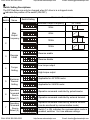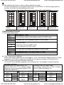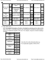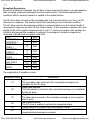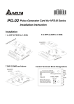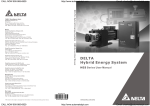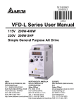
1
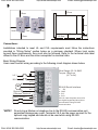
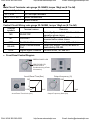
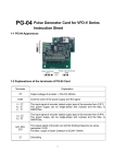
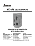
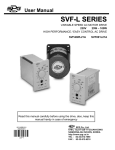
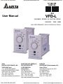
CALL NOW 800-985-6929
http://www.automatedpt.com
User Manual
Email: [email protected]
VFD-L
VARIABLE SPEED AC MOTOR DRIVE
115V/230V
25W – 100W
HIGH PERFORMANCE / EASY CONTROL AC DRIVE
ASIA
DELTA ELECTRONICS, INC.
TAOYUAN Plant/
31-1, SHIEN PAN ROAD,
KUEI SAN INDUSTRIAL ZONE
TAOYUAN 333, TAIWAN
TEL: 886-3-362-6301
FAX: 886-3-362-7267
http://www.deltaww.com/acdrives
CALL NOW 800-985-6929
NORTH/SOUTH AMERICA
EUROPE
DELTA PRODUCTS
DELTRONICS (Netherlands) B.V.
CORPORATION
Sales Office/
Industriegebied Venlo Nr. 9031
Sales Office/
P.O. BOX 12173
Columbusweg 20
5101 DAVIS DRIVE
NL-5928 LC Venlo
RTP, NC 27709 U. S. A.
The Netherlands
TEL: 1-919-767-3813
TEL: 31-77-324-1930
FAX: 1-919-767-3969
FAX: 31-77-324-1931
http://www.deltaww.com/acdrives
http://www.automatedpt.com
Email: [email protected]
CALL NOW 800-985-6929
http://www.automatedpt.com
Email: [email protected]
1
Preface
Thank you for choosing Delta’s high-performance VFD-L Series. VFD-L Series are
manufactured by adopting high-quality components, material and incorporating the latest
microprocessor technology available.
This manual will be helpful in the installation, parameter setting, troubleshooting, and daily
maintenance of the AC motor drives. To guarantee safe operation of the equipment, read
the following safety guidelines before connecting power to the AC motor drives. Keep this
operating manual handy and distribute to all users for reference.
Receiving and Inspection
This VFD-L AC drive has gone through rigorous quality control tests at the factory before
shipment. After receiving the AC motor drive, please check for the following:
Receiving
Check to make sure that the package includes an AC drive and the User Manual.
Inspect the unit to insure it was not damaged during shipment.
Make sure that the part number indicated on the nameplate corresponds with the part
number of your order.
Nameplate Information:
Example of 100W 230V AC drive
AC Drive Model
Input Spec.
Output Spec.
Output Frequency
Bar Code
Serial Number
MO DE :VFD001L21A
INPUT :1PH 200-240V 50/60Hz 1.4A
OUTP UT:3PH 0-240V 0.8A 303VA 100W
Freq. Range:1.00~120.00Hz
001L21AT001007
DELTA ELECTRONICS, INC.
MADE IN XXXXXX
Model Explanation and Series Number Explanation:
VFD 001 L 21 A
T 2 01 007
Version Type
Input Voltage
Production number
VFD-L Series
Applicable motor capacity
Production week
Series Name
Production factory (Taoyuan)
001:60/100(W)
40W:25/40(W)
Production year 2002
If there is any nameplate information not corresponding to your purchase order or any
problem, please contact your supplier.
! DANGER! AC input power must be disconnected before any maintenance. Do not
connect or disconnect wires and connectors while power is applied to the circuit.
! CAUTION! There are highly sensitive MOS components on the printed circuit boards.
These components are especially sensitive to static electricity. Do not touch these
components or the circuit boards with metal objects or your bare hands.
! CAUTION! Ground the VFD-L using the ground terminal. The grounding method must
comply with the laws of the country where the AC drive is to be installed.
CAUTION! Heat sink may heat up over 70oC (158oF), during the operation. Do not
touch the heat sink.
CALL NOW 800-985-6929
http://www.automatedpt.com
Email: [email protected]
CALL NOW 800-985-6929
http://www.automatedpt.com
Email: [email protected]
2
Storage and Installations
Storage:
The AC drive should be kept in the shipping carton before installation. In order to retain the warranty
coverage, the AC drive should be stored properly when it is not to be used for an extended period of time.
Ambient Conditions:
Operation
Storage
Transportation
Air Temperature:
Atmosphere pressure:
Installation Site Altitude:
Vibration:
Temperature:
Relative Humidity:
Atmosphere pressure:
Temperature:
-10o C to +40o C (14o F to 122o F)
86 to 106 kPa
below 1000m
Maximum 9.86 m/s2 (1G) at less than 20Hz
Maximum 5.88 m/s2 (1G) at 20Hz to 50Hz
-20o C to + 60o C (-4o F to 140o F)
Less than 90%, no condensation allowed
86 to 106 kPa
-20o C to +60o C (-4o F to 140o F)
Relative Humidity: Less than 90%, no condensation allowed
Atmosphere pressure: 86 to 106 kPa
2
Vibration: Maximum 9.86 m/s (1G) at less than 20Hz
Maximum 5.88 m/s2 (1G) at 20Hz to 50Hz
Installations and Connection:
CAUTION
The control, power supply and motor leads must be laid separately. They must not be fed
through the same cable conduit / trucking.
High voltage insulation test equipment must not be used on cables connected to the drive.
Wait five minutes for DC bus capacitors discharge.
Any Electrical or mechanical modification to this equipment without prior written
consent of Delta Electronics, Inc. will void all warranties and may result in a safety
hazard in addition to voiding the UL listing.
Short Circuit Withstand:
Suitable for use on a circuit capable of delivering not more than 5,000 rms symmetrical amperes, for 230V
Models, the maximum is 240 Volts.
Improper installation of the AC drive will greatly reduce its life. Be sure to observe the following
precautions when selecting a mounting location. Failure to observe these precautions may void the
warranty!
Do not mount the AC drive near heat-radiating elements or in direct sunlight.
Do not install the AC drive in a place subjected to high temperature, high humidity, excessive
vibration, corrosive gases or liquids, or airborne dust or metallic particles.
Mount the AC drive vertically and do not restrict the airflow to the heat sink fins.
The AC drive generates heat. Allow sufficient space around the unit for heat dissipation as
shown in the figure shown next page:
CALL NOW 800-985-6929
http://www.automatedpt.com
Email: [email protected]
CALL NOW 800-985-6929
http://www.automatedpt.com
Email: [email protected]
3
10cm
10cm
8cm
5cm
5cm
10cm
5cm
13.5cm
10cm
10cm
Connections:
Installations intended to meet UL and CUL requirements must follow the instructions
provided in “Wiring Notes” section below as a minimum standard. Where local codes
exceed these requirements, they must also be followed. Refer to the technical data label
affixed to the AC drive and the motor nameplate for electrical data.
Basic Wiring Diagram
Users must connect wiring according to the following circuit diagram shown below.
Wire Gauge: 22-14 AWG
Torque: 10kgf-cm
(8.7 in-lbf)
L/L1
N/L2
U/T1
V/T2
IM
W/T3
Digital Signal
Common Terminal
Fault Output
(Open Collector)
FWD/REV
RUN/STOP
RS-485 Serial Interface
1:+EV
2:GND
3:SG-
4:SG+
PIN 1 & 2 are the power source for
the digital keypad and should not
be used while using RS-485
communication.
*NOTE*: Do not plug a Modem or telephone line to the RS-485 communication port,
permanent damage may result. Terminals 2 & 5 are the power sources for the
optional copy keypad and should not be used while using RS-485
communication.
CALL NOW 800-985-6929
http://www.automatedpt.com
Email: [email protected]
CALL NOW 800-985-6929
http://www.automatedpt.com
Email: [email protected]
4
Main Circuit Terminals: wire gauge 22-14AWG, torque 10kgf-cm (8.7 in-lbf)
Terminal Symbols
Terminal Functions
L/L1, N/L2
U/T1, V/T2, W/T3
AC line input terminals
Motor connections
Earth Ground
Control Circuit Wiring: wire gauge 22-14AWG, torque 10kgf-cm (8.7 in-lbf)
Terminal
Terminal names
Remarks
symbols
Normally Open contact, AC drive starts
M0
RUN/STOP
operation when closes.
Normally Open contact, AC drive starts
M1
FWD/REV
reverse motion when closes.
MO1
Fault Indication
When error is detected, MO1 will close.
Serial Communication
When DIP Switch 7 is ON, the drive is
RS-485
Port
controlled by RS-485.
DCM
Digital Signal Common Ground for M0, M1 and M01
Front Panel Control Diagram
GREEN POWER LED
RED ERROR LED
(Please refer to
troubleshooting & Fault
Information)
Accel/Decel Time(Sec)
Output frequency (%)
30
100
5
0.05
Accel/Decel Time Knob (sec.)
CALL NOW 800-985-6929
5
10
Unit
0 1
Unit
9 10
Output Frequency Knob (Hz)
http://www.automatedpt.com
Email: [email protected]
CALL NOW 800-985-6929
http://www.automatedpt.com
Email: [email protected]
5
Switch Setting Descriptions:
The DIP Switches can only be changed when AC drive is in a stopped mode.
Indicates the position of the switch (ON/OFF).
DIP
Switch
Switch
Name
Switch Setting
Maximum Output Frequency
ON
1 2 3 4 5 6 7
1
ON
Max.
1 2 3 4 5 6 7
Output
Frequency ON
1 2 3 4 5 6 7
2
ON
1 2 3 4 5 6 7
ON
3
Reverse
Inhibit
1 2 3 4 5 6 7
ON
1 2 3 4 5 6 7
ON
4
Torque
Setting
1 2 3 4 5 6 7
ON
1 2 3 4 5 6 7
ON
5
Electronic
1 2 3 4 5 6 7
Thermal
ON
Setting
1 2 3 4 5 6 7
ON
6
Operation
1 2 3 4 5 6 7
Command
Source ON
Select (1)
1 2 3 4 5 6 7
ON
7
Operation
1 2 3 4 5 6 7
Command
Source ON
Select (2)
1 2 3 4 5 6 7
CALL NOW 800-985-6929
Parameter Descriptions
50Hz
V/F Curve
100%
100%
60Hz
100%
100Hz
100%
120Hz
f 50Hz
f 60Hz
f 50Hz 100Hz
f 60Hz 120Hz
Reverse enable
Reverse disable
Low torque output
High torque output
Applicable for 40/100W motor
Applicable for 25/60W motor
Operation command controlled by potentiometer.
Operation command controlled by external terminal
Operation command controlled by external terminal
(can be monitored by communication mode)
Switch 7 is ON, indicates the communication mode is
enabled; switches 1 to 6 are address settings.
http://www.automatedpt.com
Email: [email protected]
CALL NOW 800-985-6929
http://www.automatedpt.com
Email: [email protected]
6
Communication
There is three control modes: RS-485 communication, AC drive front panel, and external terminals. Only
one mode can be used at a time and is selected by DIP Switch 6 and 7. Programming can only be done
when the AC drive is in stopped mode.
DIP switch settings for control
DIP Switch 6 determines if control is via the AC drives front panel or external terminals. Set DIP switch
6 to OFF for AC drive front panel control and ON for external terminal control
DIP Switch 7 determines if control is local or via RS-485 communication. When DIP Switch 7 is OFF,
the AC drive front panel or external terminals control the drive.
Note: The parameters set via RS-485 communication will remain in memory. Users can still read the status
of the AC drive via RS-485 communication, but cannot send any control commands.
When DIP Switch 7 is ON, the drive is controlled by RS-485 communication. Please verify the AC drive is
fully stopped prior to turn DIP Switch 7 ON. If DIP Switch 7 is turned ON during operation, the error LED
will illuminate.
Computer Controls
Each VFD-L AC Drive has a pre-assigned communication address specified by DIP Switch pins 1 to 6
(Refer to the description of setting up address). VFD-L type Communication agreement: Modbus ASCII
mode, protocol <7, N, 2>, Baud rate 9600. The computer then controls each AC Drive according to its
communication address.
ASCII Modes:
Each 8-bit data is the combination of two ASCII characters. For example, a 1-byte data: 64 Hex, shown as
‘64’ in ASCII, consists of ‘6’ (36Hex) and ‘4’ (34Hex).
Character
ASCII code
Character
ASCII code
‘0’
‘1’
‘2’
‘3’
‘4’
‘5’
‘6’
‘7’
30H
31H
32H
33H
34H
35H
36H
37H
‘8’
‘9’
‘A’
‘B’
‘C’
‘D’
‘E’
‘F’
38H
39H
41H
42H
43H
44H
45H
46H
Data Format
10-bit character frame (For 7-bit character):
Start
bit
0
1
2
3
4
(7, N, 2)
5
6
Stop
bit
Stop
bit
7-data bits
10-bits character frame
AC Drive Addresses for RS-485 Communication
VFD-L series communication addresses are 1 to 63, since 0 means broadcast to all AC drives. A DIP
Switch sets to ON for equal to 1 and OFF for equal to 0.
If DIP Switch 7 is OFF during power up, the communication address for the drive is 0008H, this is address
1 (factory default).
If DIP Switch 7 is ON during power up, the address settings are determined by the ON/OFF positions of
DIP Switches 1 to 6. Address 1 is when all switches are set to the OFF position. Switch “1” is the upper bit
and switch 6 is the lower bit.
(A) The addresses will remain in memory when the control mode changes to AC drive panel or external
terminals.
CALL NOW 800-985-6929
http://www.automatedpt.com
Email: [email protected]
CALL NOW 800-985-6929
http://www.automatedpt.com
Email: [email protected]
7
(B) The addresses will remain in memory when parameters are reset.
To save new addresses, remove power from the drive, set DIP switch 7 to ON and reapply power to
the drive, at this time the new addresses will be read.
Examples of setting up the address (Black block means ON or OFF of DIP SWITCH):
1
2
3
4
5
6
7
ON
1
2
3
4
5
6
7
Communication
Inhibits
ON
Communication
address is 01
ON
1
2
3
4
5
6
7
Communication
Address is 01
ON
1
2
3
4
5
6
7
Communication
Address is 02
1
2
3
4
5
6
7
ON
Communication
Address is 63
Communication Protocol
Communication Data Frame:
STX
Start character ‘:’ (3AH)
ADR 1
Communication address: 8-bit address consists of 2 ASCII codes
ADR 0
CMD 1
Command code: 8-bit command consists of 2 ASCII codes
CMD 0
DATA (n-1) Contents of data:
n×8-bit data consist of 2n ASCII codes.
To
n<=25, maximum of 50 ASCII codes
DATA 0
LRC CHK 1
LRC check sum: 8-bit check sum consists of 2 ASCII codes
LRC CHK 0
END 1
End characters: END1 = CR (0DH), END0 = LF (0AH)
END 0
ADR (Communication Address)
Valid communication addresses are in the range of 1 to 63. Communication address equal to 0, means
broadcast to all AC drives. In this case, the AMD will not reply any message to the master device.
CMD (Command code) and DATA (data characters)
The format of data characters depends on the command code. The available command codes are
described as followed:
Command code: 03H, read N words. The
Command code: 06H, write 1 word
maximum value of N is 12. For example, reading
For example, writing 6000 (1770H) to address
continuous 2 words from starting address 2102H
2001H of AMD with address 01H.
of AMD with address 01H
Command message:
Response message:
Command message: Response message:
STX
ADR 1
ADR 0
CMD 1
CMD 0
‘:’
‘0’
‘1’
‘0’
‘3’
CALL NOW 800-985-6929
STX
ADR 1
ADR 0
CMD 1
CMD 0
‘:’
‘0’
‘1’
‘0’
‘3’
STX
ADR 1
ADR 0
CMD 1
CMD 0
http://www.automatedpt.com
‘:’
‘0’
‘1’
‘0’
‘6’
STX
ADR 1
ADR 0
CMD 1
CMD 0
‘:’
‘0’
‘1’
‘0’
‘6’
Email: [email protected]
CALL NOW 800-985-6929
http://www.automatedpt.com
Email: [email protected]
8
‘2’
Starting data
address
‘1’
‘0’
‘2’
Number of
data
(Count by
word)
LRC CHK 1
LRC CHK 0
‘0’
‘0’
‘0’
‘2’
‘D’
‘7’
END 1
END 0
CR
LF
Number of data
(byte)
Content of
starting data
address
2102H
Content of data
address 2103H
LRC CHK 1
LRC CHK 0
END 1
END 0
‘0’
‘2’
‘2’
‘4’
‘1’
‘7’
‘7’
‘0’
‘0’
‘0’
‘0’
‘0’
‘7’
‘1’
‘0’
‘0’
‘0’
‘0’
CR
LF
Data address
Data content
LRC CHK 1
LRC CHK 0
END 1
END 0
Data address
‘1’
‘1’
‘1’
‘7’
‘7’
‘0’
“5’
‘1’
‘1’
‘7’
‘7’
‘0’
‘5’
‘1’
CR
LF
Data content
LRC CHK 1
LRC CHK 0
END 1
END 0
CR
LF
CHK (check sum)
LRC (Longitudinal Redundancy Check) is calculated by summing up the values of the
bytes from ADR1 to last data character then calculating the hexadecimal representation
of the 2’s-complement negation of the sum. For example, using the command message
of above:
STX
‘:’
ADR 1
‘0’
ADR 2
‘1’
CMD 1
‘0’
CMD 2
‘3’
‘2’
STARTING DATA
‘1’
ADDRESS
‘0’
01H+03H+21H+02H+00H+02H=29H, the
‘2’
2’s-complement negation of 29H is D7H.
‘0’
NUMBER OF
‘0’
DATA
‘0’
‘2’
LRC CHK 1
‘D’
LRC CHK 0
‘7’
END 1
CR
END 0
LF
CALL NOW 800-985-6929
http://www.automatedpt.com
Email: [email protected]
CALL NOW 800-985-6929
http://www.automatedpt.com
9
Parameters (saved in the EEPROM)
Parameter
Identity code of Drive
Rating current
Parameter Reset
3
Max. Operation Freq.
4
: the parameter can be set during the operation.
Parameter Function
0
1
2
Email: [email protected]
Accel/Decel Time
5
Reverse Inhibit
6
Torque Increase
7
Electronic Thermal
8
9
Communication Addresses
Software Version
Parameter Setting
Depend on drive
Depend on drive
10: Reset
0: 50 Hz
1: 60 Hz
2: 100 Hz
3: 120 Hz
0.05 to 30.00 sec
0: Reverse
disable
1: Reverse
enable
0: High Torque
1: Low Torque
0: 25/60 w
1: 40/100 w
01 to 63
Read only
Factory
Setting
Customer Setting
1
0
Read only
Read/Write
Read/Write
1
Read Only
5.00
Read/Write
1
Read/Write
1
Read/Write
1
Read/Write
1
#.#
Read/Write
Read Only
Address List:
The contents of available addresses are shown as below:
Content:
Address:
AC drive
Parameters
nnnnH
2000H
Command
Write only
2001H
2002H
CALL NOW 800-985-6929
Function:
nnnn means parameter number, for example, the address of 0004 is
0004H. When reading parameter by command code 03H, only one
parameter can be read at one time.
00B: No function
01B: Stop
Bit 0 to 1
10B: Run
11B: No function
Bit 2 to 3 Reserved
00B: No function
01B: FWD
Bit 4 to 5
10B: REV
11B: Change direction
Bit 6 to 15 Reversed
Frequency command
Bit 0
1: Reversed
Bit 1
1: Reset
Bit 2-15 Reserved
http://www.automatedpt.com
Email: [email protected]
CALL NOW 800-985-6929
10
Content:
http://www.automatedpt.com
Address:
2100H
Status monitor
(Read only)
2101H
2102H
2103H
2104H
2105H
2106H
CALL NOW 800-985-6929
Email: [email protected]
Function:
Error Codes
00: No error occurred
01: Over-current (oc)
02: Over-voltage (ov)
03: Overheat (oH)
04: Overload (oL)
05, 06: Reserved
07: CPU failure (cF3)
08 to 13: Reserved
14: Low voltage (Lv)
15: CPU failure 1 (cF1)
16: CPU failure 2 (cF2)
17 to 19: Reserved
20: Software protection
21: Operation error
22: OH Hardware failure cF3.1
23: OV Hardware failure cF3.2
24: LV Hardware failure cF3.3
26: Hardware failure cF3.5 (current detection)
30: Hardware failure hpf.2
31: Hardware failure hpf.3
00: STOP
01: Ramp stop
Bit 0 to 1
10: Zero speed
11: Operation
Bit 2
Reserved
00: Forward motion
01: from Reverse to Forward motion
Bit 3 to 4
10: from Forward to Reverse motion
11: Reverse motion
Bit 5 to 9
Reserved
1: Operation commands are controlled
Bit 10
by communication interface.
Bit 11 to 15
Reserved
Frequency Command F (XXX.XX)
Output Frequency H (XXX.XX)
Output Current A (X.XX)
DC-BUS Voltage (XXX)
Output Voltage E (XXX.X)
http://www.automatedpt.com
Email: [email protected]
CALL NOW 800-985-6929
http://www.automatedpt.com
Email: [email protected]
11
Exception Responses:
Except for broadcast messages, the AC drive is been expected to return a normal response
after receiving command messages from the master device. The following depicts the
conditions that no normal response is replied to the master device.
The AC drive does not receive the messages due to a communication error; thus, the AC
drive has no response. The master device will eventually process a timeout condition.
The AC drive receives the messages without a communication error, but cannot handle it,
an exception response will return to the master device. In the exception response, the most
significant bit of the original command code is set to 1, and an exception code explains the
condition that caused the exception is returned. An example of exception response of
command code 06H and exception code 02H:
STX
‘:’
3AH
ADDRESS 1
‘0’
30H
ADDRESS 0
‘1’
31H
FUNCTION
‘8’
38H
(CMD) 1
FUNCTION
‘6’
36H
(CMD) 0
EXCEPTION
‘0’
30H
CODE
‘2’
32H
LRC CHK 1
‘7’
43H
LRC CHK 0
‘7’
46H
END 1
CR
0DH
END 0
LF
0AH
The explanation of exception codes:
Exception codes:
01
02
03
04
09
20
CALL NOW 800-985-6929
Explanation
Illegal command code:
The command code received in the command message is not
available for the AC drive.
Illegal data address:
The data address received in the command message is not available
for the AC drive.
Illegal data value:
The data value received in the command message is over range for
the AC drive.
Slave device failure:
The AC drive is unable to perform the requested action.
Check Sum Error: Check if the Check Sum is correct.
Watchdog Timer: The timer will reset to 0 after each valid MODBUS
communication message is received.
http://www.automatedpt.com
Email: [email protected]
CALL NOW 800-985-6929
http://www.automatedpt.com
Email: [email protected]
12
Maintenance and Inspections
Modern AC drives are based on solid state electronics technology, preventive maintenance
is required to operate this AC drive in its optimal condition, and to ensure a long life. It is
recommended to perform a monthly check up of the AC drive by a qualified technician.
Before the check up, always turn off the AC Input Power to the unit. Wait at least 2 minutes
after all display lamps have gone out, and then confirm that the capacitors have fully
discharged.
Periodic Inspection:
Basic check up items to detect if there were any abnormality during the operation.
1. Whether the motors are operating as expected.
2. Whether the installation environment is abnormal.
3. Whether the cooling system is operating as expected.
4. Whether any irregular vibration or sound occurred during the operation.
5. Whether the motors are overheated during the operation.
6. Always check the input voltage of the AC drive with Voltmeter.
Periodic Maintenance:
It is necessary to stop the motor operation during the check up.
1. Tighten and reinforce the screws of the AC drive if necessary, cause it may loose due to
the vibration or changing of temperatures.
2. Whether the conductors or insulators were corroded and damaged.
3. Check the resistance of the insulation with Megaohmeter.
4. Often check and change the capacitors and relays.
5. If use of the AC drive is discontinued for a long period of time, turn the power on at least
once every two years and confirm that it still functions properly. To confirm functionality,
disconnect the motor and energize the AC drive for 5 hours or more before attempting
to run a motor with it.
6. Clean off any dust and dirt with a vacuum cleaner. Place special emphasis on cleaning
the ventilation ports and PCBs. Always keep these areas clean, as adherence of dust
and dirt can cause unforeseen failures.
Fuse and Fuse Breaker (NFB) Specifications:
Model
40W 115V
40W 230V
100W 115V
100W 230V
CALL NOW 800-985-6929
Ampere Rating (A)
6.0A
3.0A
10.0A
6.0A
Manufacturer (Reference)
Busmann - JJN-6 300V
Busmann - JJN-3 300V
Bssmann - JJN-10 300V
Bssmann - JJN-6 300V
http://www.automatedpt.com
Email: [email protected]
CALL NOW 800-985-6929
http://www.automatedpt.com
Email: [email protected]
13
Troubleshooting and Fault Information
The AC drive has a comprehensive fault diagnostic system that includes several different
alarms and fault message. Once a fault is detected, the corresponding protective functions
will be activated to shut down the AC drive output. Below are the fault descriptions, for a
fault shown on the AC drive digital keypad. After fault has been cleared, switch the
Run/Stop key to stop mode to reset the drive.
Fault Display
Alarm LED lighten after
power on
Alarm LED flashes once
in every two seconds
Fault Descriptions
Hardware failure
Corrective Actions
Return to the factory
1. Increase the acceleration time
2. Check whether the motor output power
corresponds to the AC drive output
The AC drive
power
detects an
abnormal increase 3. Check the wiring connection between the
AC drive and motor for possible short
in current
circuit
(Over-current)
4. Check for possible over loading
conditions at the motor
The AC drive
detects that the
Alarm LED flashes twice DC-BUS voltage
in every two seconds
has exceeded its
(Over-voltage)
maximum
allowable value
1. Check whether the input voltage falls
within the rated AC Drive input voltage.
2. Check for possible voltage transients.
3. Bus over-voltage may be caused by
motor regeneration, increase the
accel/decel time.
Alarm LED flash thrice in
every two seconds
Motor overload
(Overload)
1. Check for possible motor overload.
2. Adjust torque detection setting of the DIP
SW4 to an appropriate setting.
3. Increase the AC Drive’s output capacity.
Alarm LED flashes four
times in every two
seconds
(Over-heating)
The AC drive
temperature
sensor detects
excessive heat.
1. Ensure that the ambient temperature
falls within the specified temperature
range.
2. Make sure that the ventilation holes are
not obstructed.
3. Provide enough spacing for adequate
ventilation.
Alarm LED flashes five
times in every two
seconds
(Low voltage)
The AC drive
detects that the
Check whether the input voltage falls within
DC Bus Voltage
the rated AC Drive input voltage.
has fallen below
its minimum value.
Alarm LED flashes
Change DIP SW
while drive is
running
CALL NOW 800-985-6929
Switch the Run/Stop key to Stop mode to
reset the AC drive.
http://www.automatedpt.com
Email: [email protected]
CALL NOW 800-985-6929
http://www.automatedpt.com
Email: [email protected]
14
Standard Specifications
Operation
Characteristics
Control
Characteristics
Input Rating Output Rating
Voltage Class
Model Number VFDL A/B
Weight g (lb) A (standard)
Weight g (lb) B (build-in EMI filter)
Max. Applicable Motor Output (W)
Rated Output Capacity (VA)
Rated Output Current (A)
Maximum Output Voltage (V)
Rated Frequency (Hz)
Rated Voltage/Frequency
Voltage/Freq. Tolerance
Control Systems
Torque Setting
Overload Endurance
Accel/Decel Time
Torque Promotion
Frequency Setting
Operation Setting Panel
Signal
Ext. Terminal
Panel
Output Indiction
Ext. Terminal
Cooling
Installation Location
Environment
Voltage: ±10%, Frequency: ±5%
1.1A 1.5A 2.2A 3.0A 0.5A 0.7A 1.0A 1.4A
SVPWM (Space Vector Pulse Width Modulation,
carrier frequency 10kHz)
High/Low, Switching
150% of rated current for 1 minute
0.05 to 30.0 seconds
Input Current (A)
Protection
Pollution Degree
Ambient Temperature
Storage Temperature
Ambient Humidity
Vibration
CALL NOW 800-985-6929
115V Class
230V Class
40W
001
40W
001
270 (0.60) 440 (0.97) 260 (0.57) 430 (0.95)
350 (0.77) 525 (1.16) 340 (0.75) 510 (1.12)
25/40
60/100
25/40
60/100
106/152
212/303
106/152
212/303
0.28/0.4
0.56/0.8
0.28/0.4
0.56/0.8
Two times proportion to
Proportional to Input
Input Voltage
Voltage
1.00 to 120.00 Hz
Single phase
Single phase
100 to 120 VAC
200 to 240 VAC 50/60Hz
50/60 Hz
Torque Boots: 0 or 8%
Potentiometer
RUN/STOP, FORWARD/REVERSE
RUN/STOP, FORWARD/REVERSE, RS-485
Fault Indication (LED Flash)
Fault Indication (Open Collector)
Self-testing, Over Voltage, Over Current, Under
Voltage, Overload, Overheating, Thermal.
Natural air-cooling
Altitude 1,000m or lower, keep from corrosive
gasses, liquid and dust
2
-10oC to 40oC (Non-Condensing and not frozen)
-20oC to 60oC
Below 90% RH (non-condensing)
9.80665m/s2 (1G) less than 20Hz, 5.88m/s2
(0.6G) at 20 to 50Hz
http://www.automatedpt.com
Email: [email protected]
CALL NOW 800-985-6929
http://www.automatedpt.com
Email: [email protected]
15
52.5 [2.07]
Dimensions
2.7 [0.11]
8.0 [0.31]
VFD40WL11A
VFD40WL21A
VFD001L11A
VFD001L21A
125.1 [4.93]
60.0 [2.36]
Unit: mm [inch]
135.7 [5.34]
52.5 [2.07]
STOP
FWD
RUN
L/L1
N/L2
U/T1
V/T2
W/T3
REV
52.5 [2.07]
4.5[ 0.18]
2.7 [0.11]
8.0 [0.31]
RS485
VFD40WL11B
VFD40WL21B
VFD001L11B
VFD001L21B
Unit: mm [inch]
145.1 [5.71]
60.0 [2.36]
80.0 [3.15]
Low
80.0 [3.15]
100.0 [3.94]
ALARM
90.0 [3.54]
POWER
High
155.7 [6.13]
52.5 [2.07]
STOP
FWD
RUN
REV
4.5[ 0.18]
L/L1
N/L2
U/T1
V/T2
W/T3
90.0 [3.54]
80.0 [3.15]
Low
100.0 [3.94]
ALARM
80.0 [3.15]
POWER
High
RS485
+1
81- 0 [3.19]
90± 0.2 [3.54]
SCREW
M4 or Tapping 4(2x)
+1
0
53-
9]
[2.0
Unit : mm [inch]
CALL NOW 800-985-6929
http://www.automatedpt.com
Email: [email protected]