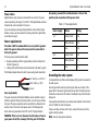
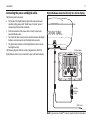
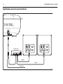
1
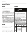
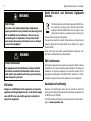
Digital Radome
Scanner
User Guide
Document number: 81313-3
Date: February 2009
Trademarks and registered trademarks
Autohelm, HSB, RayTech Navigator, Sail Pilot, SeaTalk and Sportpilot are
UK registered trademarks of Raymarine UK Limited. Pathfinder and Raymarine are UK registered trademarks of Raymarine Holdings Limited.
45STV, 60STV, AST, Autoadapt, Auto GST, AutoSeastate, AutoTrim, Bidata,
GSeries, HDFI, LifeTag, Marine Intelligence, Maxiview, On Board, Raychart,
Raynav, Raypilot, RayTalk, Raystar, ST40, ST60+, Seaclutter, Smart Route,
Tridata and Waypoint Navigation are trademarks of Raymarine UK Limited.
All other product names mentioned are trademarks or registered trademarks (if applicable) of their respective companies.
© Raymarine UK Ltd 2009
Contents
i
Contents
Important information ................................................................1
Introduction........................................................................................... 1
Intended use ......................................................................................... 1
Safety notices ........................................................................................ 1
FCC Notice ............................................................................................ 2
WARNING ............................................................................................. 2
WARNING ............................................................................................. 2
Waste Electrical and Electronic Equipment Directive............................. 2
EMC conformance ................................................................................. 2
Declaration of conformity...................................................................... 2
Multi-function display software version ................................................ 3
Warranty ............................................................................................... 3
Handbook information .......................................................................... 3
Installation ....................................................................................5
EMC installation guidelines................................................................... 5
Box contents ......................................................................................... 6
Required tools ....................................................................................... 6
Digital Radome scanner dimensions...................................................... 7
18” Digital Radome scanner.............................................................. 7
24” Digital Radome scanner.............................................................. 7
Planning the installation ....................................................................... 8
Cable requirements ............................................................................... 9
Scanner cables................................................................................... 9
Running the cable to the scanner ...................................................... 9
Power requirements......................................................................... 10
Grounding the radar system ............................................................ 10
Connecting the power and digital cables......................................... 11
Mounting the scanner ..................................................................... 14
Setting up the scanner ..................................................................... 15
Maintenance and troubleshooting .......................................... 17
Introduction ..................................................................................... 17
Maintenance.................................................................................... 17
Troubleshooting............................................................................... 17
Technical support............................................................................. 19
Technical specification.............................................................. 21
RD418D 18”Digital Radome scanner unit .......................................... 21
RD424D 24”Digital Radome scanner unit .......................................... 23
ii
Digital Radome Scanner - User Guide
Important information
1
Important information
Introduction
Safety notices
This handbook contains an explanation of how to install, connect and
maintain your Digital Radome scanner and covers the following models:
• RD418D - 18” 4 kW Digital Radome scanner.
• RD424D - 24” 4 kW Digital Radome scanner.
Your radar has been designed and manufactured to meet the rigorous
demands of the marine environment. However, no machine can perform its
intended function unless installed, operated and maintained properly.
Please carefully read and follow the recommended procedures for installation contained in this handbook.
When properly installed and operated, the use of this radar conforms to:
•
•
IEEE C95.1 - 2005 - Standard for Safety Levels with respect to Human
Exposure to Radio Frequency Electromagnetic Fields, 3 kHz to 300GHz.
ICNIRP Guidelines 1998 - International Commission on Non-Ionising
Radiation Protection: Guidelines for limiting exposure to time-varying
electric, magnetic and electro-magnetic fields (up to 300GHz) 1998.
WARNING
Radio Frequency Radiation Hazard
The radar antenna emits electromagnetic energy at microwave radio frequencies which can be harmful, particularly to
your eyes. DO NOT look at the antenna at close range.
It is important that the radar is turned off whenever personnel
are required to come close to the scanner assembly. It is
recommended that the radar scanner is mounted out of range
of personnel (above head height).
The maximum power density level which is considered safe for
general public exposure is 10 W/m2, and for occupational exposure it is 100 W/m2. The distances from the radar scanner
within which these levels may be exceeded are given below:
Intended use
Model
This product is a radar scanner intended for use within a navigational radar
system. The intended application is for leisure marine boats and work
boats not covered by IMO/SOLAS carriage requirements.
RD418D
Installation and operation of this radar may be subject to individual
licensing of the equipment, operator or vessel. You are strongly advised to
check with the requirements of the licensing authority of your national
administration. In case of difficulty, contact your local Raymarine dealer.
RD424D
Distance to 100 W/m2
point
Max power density at any
distance is <100 W/m2
Max power density at any
distance is <100 W/m2
Distance to 10 W/m2
point
1.0m (worst case)
1.0m (worst case)
2
Digital Radome Scanner - User Guide
WARNING
High Voltage
The scanner unit contains high voltages. Adjustments
require specialized service procedures and tools only available to qualified service technicians - there are no user
serviceable parts or adjustments. The operator should
never remove the scanner unit internal covers or attempt
to service the equipment.
WARNING
Product installation
This equipment must be installed in accordance with the
instructions contained in this handbook. Failure to do so
could result in poor product performance, personal injury
and/or damage to your boat.
Waste Electrical and Electronic Equipment
Directive
The Waste Electrical and Electronic Equipment (WEEE) Directive requires the recycling of waste electrical and electronic
equipment. Whilst the WEEE Directive does not apply to some
of Raymarine’s products, we support its policy and ask you to
be aware of how to dispose of this product.
The crossed out wheelie bin symbol, illustrated above, and found on our
products signifies that this product should not be disposed of in general
waste or landfill.
Please contact your local dealer, national distributor or Raymarine Technical Services for information on product disposal.
EMC conformance
All Raymarine equipment and accessories are designed to the best industry
standards for use in the recreational marine environment. The design and
manufacture of Raymarine equipment and accessories conform to the
appropriate Electromagnetic Compatibility (EMC) standards, but correct
installation is required to ensure that performance is not compromised.
FCC Notice
Declaration of conformity
Changes or modifications to this equipment, not expressly
approved in writing by Raymarine Inc., could violate compliance with FCC rules and void the operator’s authority to
operate the equipment.
Raymarine UK Limited hereby declare that the products to which this
manual relates comply with the appropriate requirements and provisions of
the R&TTE Directive 1999/5/EC.
The full Declaration of Conformity may be viewed on the relevant product
pages at www.raymarine.com
Important information
3
Multi-function display software version
Handbook information
The Digital Radome scanner can be connected directly to a C-Series or
E-Series display, or to a C-Series, E-Series or G-Series display via a
SeaTalkhs switch.
The technical and graphical information contained in this handbook, to the
best of our knowledge, was correct as it went to press. However, our policy
of continuous improvement and updating may change product specifications without prior notice. As a result, unavoidable differences between the
product and handbook may occur from time to time.
The Digital Radome scanner is compatible with the following multi-function displays:
• C90W, C120W, and C140W C-Series displays.
• E80, E120 E-Series displays.
• G120, G150, G170, and G190 G-Series displays.
For operation of your scanner, the multi-function display unit requires the
latest software version.
After installing your scanner, download the latest software for your multifunction display from the Raymarine website (www.raymarine.com).
To find out whether your display is using the latest software version, switch
on the display and check the version number on the navigation warning
screen. However, if a scanner is not connected to the multi-function
display, the version number will only be displayed for 10 seconds.
For information on how to update your multi-function display software,
please refer to the instructions on the Raymarine website, or contact
Raymarine technical support.
Warranty
To register your new Raymarine product, please take a few minutes to fill
out the warranty card. It is important that you complete the owner information and return the card to receive full warranty benefits. Alternatively
you can register your product on line at www.raymarine.com
4
Digital Radome Scanner - User Guide
Installation
5
Installation
EMC installation guidelines
All Raymarine equipment and accessories are designed to the best industry
standards for use in the recreational marine environment.
Their design and manufacture conforms to the appropriate Electromagnetic
Compatibility (EMC) standards, but correct installation is required to
ensure that performance is not compromised. Although every effort has
been taken to ensure that they will perform under all conditions, it is
important to understand what facts could affect the operation of the
product.
The guidelines here describe the conditions for optimum EMC performance,
but it is recognized that it may not be possible to meet all of these conditions in all situations. To ensure the best possible conditions for EMC
performance within the constraints imposed by any location, always ensure
the maximum separation possible between different items of electrical
equipment.
For optimum EMC performance, it is recommended wherever possible:
•
•
Raymarine equipment and cables connected to it are:
• At least 3 ft. (1m) from any other equipment transmitting or
carrying radio signals. In the case of Single Side Band (SSB) radio,
the distance should be increased to 7 ft. (2m).
• More than 7 ft. (2m) from the path of a radar beam. A radar beam
can normally be assumed to spread 20 degrees above and below
the radiating element.
The equipment is supplied from a separate battery to that used for
engine start. Voltage drops below 10.8 V, and starter motor transients,
can cause the equipment to reset. This will not damage the equipment,
but may cause the loss of some information and may change the operating mode.
•
Only Raymarine-specified cables must be used. Cutting and rejoining
these cables can compromise EMC performance.
6
Digital Radome Scanner - User Guide
Box contents
Required tools
10 mm drill bit
27.5 mm
Center Line of Radome
Radome Scanner
Spring
washer (x4)
Flat
washer (x4)
Adhesive tape
Center Line of Radome
141.5 mm
M8 bolt (x4)
Drill
Drill 4 holes, 10 mm diameter
(18'' and 24'' Radomes)
233 mm
13 mm socket
Forward
Torque wrench
D11365-1
18'' or 24'' Radome Mounting Template
3026-136-C
Artwork Number 3032-866-B
Denso Paste
Installation template
D11364-2
Components are dependant on your system package, but are either:
•
•
•
•
•
18” 4 kW Digital Radome scanner, or
24” 4 kW Digital Radome scanner.
Fixing bolts and washers.
Denso Paste.
Handbook.
Installation
7
Digital Radome scanner dimensions
247 mm (9.7 in)
24” Digital Radome scanner
247 mm (9.7 in)
18” Digital Radome scanner
346 mm (13.62 in)
diameter
346 mm (13.62 in)
diameter
27.5 mm
(0.92 in)
233 mm
(9.17 in)
116.5 mm
(4.58 in)
652 mm (25.67 in)
diameter
233 mm
(9.17 in)
116.5 mm
(4.58 in)
521 mm (20.5 in)
diameter
27.5 mm
(1.08 in)
141.5 mm
(5.57 in)
141.5 mm
(5.57 in)
D11356-1
D11357-1
8
Digital Radome Scanner - User Guide
Planning the installation
12.5°
12.5°
D11359-1
Mount the scanner so that the array rotates parallel to the waterline.
The radar beam is approximately 25o wide in the vertical direction, giving
good target detection when your boat pitches and rolls.
D11358-1
Mount the scanner as high as possible above the waterline for better long
range performance, but make sure it:
•
•
•
•
•
is above head height.
is easily accessible.
is as near to the boat’s centerline as possible.
is on a rigid and stable platform.
is clear of large objects such as the flybridge, large engine stacks,
searchlights, horns or masts.
• is clear of heat and fumes.
• is at least 1 m away from a magnetic compass or other equipment
antenna.
Don’t put the scanner so high, that it is affected by the pitching and rolling
of the boat.
Forward
Wedge or
washers
D11360-1
Planing hull and some displacement hull boats adopt a higher bow angle
when the boat is at cruising speed, giving poor target detection. It may be
necessary to lower the radar beam back towards the parallel, by shimming
the rear of the radar, so that the beam points slightly down when the boat
is at rest. Refer to the diagram on page 14 for more information.
Installation
9
Cable requirements
Digital cable
You must consider the following points before installing the system cables:
A digital cable, illustrated below, is required. This provides both power and
SeaTalkhs signals to the Digital Radome scanner. It is fitted with a
SeaTalkhs plug, and power cores for connecting to the scanner.
•
•
•
•
•
You need to connect the scanner to the multi-function display unit and
power (and, if appropriate, via a SeaTalkhs switch).
All cables should be adequately clamped and protected from physical
damage and exposure to heat - avoid running cables through bilges or
doorways, or close to moving or hot objects.
Acute bends must be avoided. The digital cable for connecting the
Digital Radome scanner to a multi-function display and power source
has a minimum bend radius of 45mm (or diameter of 90mm).
Where a cable passes through an exposed bulkhead or deckhead, a
watertight gland or swan neck tube should be used.
Avoid cutting and rejoining cables.
Scanner cables
Running the cable to the scanner
DO NOT pull the cable through bulkheads using a cord
attached to the connector. This could damage connections.
The cable connector is at the rear of the scanner unit. If the unit is mounted
on a hollow mast, the cable may be run inside the mast and connected to
the unit. Make sure that the cable does not chafe where it enters and exits
the mast. To minimize electrical interference try to avoid running radar
cables near other onboard electrical equipment. It is also good practice to
avoid running radar cables in parallel with other antenna or power cables.
To Digital Radome scanner
To display and power
D11371_1
Digital cables are available in the following lengths:
• Part No. A55076 - 5 m cable.
• Part No. A55077 - 10 m cable.
• Part No. A55078 - 15 m cable.
• Part No. A55079 - 25 m cable.
The following extension cables are also available:
• Part No. A92141 - 2.5 m extension cable.
• Part No. A55080 - 5 m extension cable.
• Part No. A55081 - 10 m extension cable.
For boats with 12 V DC power systems, the maximum cable length is 25 m
(including any extension). If you need to run a longer cable length with a
12v supply, please contact Raymarine technical support for further advice.
Note: Do not make your own cables for use with the Digital Radome
scanner. Only use official Raymarine cables.
10
Digital Radome Scanner - User Guide
Power cables
Digital Radome radar systems are intended for use on boat’s DC power
systems operating in the range 12 to 24 V DC. The Digital Radome scanners
should not be used on nominal 32 V systems.
If you are replacing an existing (Analog) Radome scanner with a Digital
Radome scanner, you must replace the existing cable with a digital cable,
as described on page 9.
tion panel), you must fit an inline breaker or fuse to the
positive (red) connection of the power cable.
Table 2-1: Fuse requirements
Power supply
Device
Rating
12 V
Isolator Switch
20 A
Thermal Breaker
10 A
Fuse
15 A
Isolator Switch
15 A
Thermal Breaker
5A
Fuse
8A
Power requirements
This radar is NOT recommended for use on ‘positive’ ground
boats. The power cable earth screen must be connected to
the boat’s ground.
The boat’s power system should be either:
•
Negative grounded, with the negative battery terminal connected to
the boat’s ground, or,
• Floating with neither battery terminal connected to the boat’s ground.
The following diagram shows the cable’s power and ground connections:
Red - Battery +ve (12/24 V)
Black - Battery -ve (0 V)
D8865_1
Ground
Fuse requirements
The power connection to the Digital Radome scanner should be made at
either the output of the battery isolator switch, or at a DC power distribution panel. The power connection must be protected by a thermal circuit
breaker or fuse, fitted close to the power source. The following table
details the fuse requirements for both 18” and 24” Digital Radomes:
WARNING: If there is not a thermal circuit breaker or fuse in
your power circuit (for example, fitted to your DC distribu-
24 V
Grounding the radar system
It is important that an effective radio frequency (RF) ground is connected to
the radar system.
You must ground the radar by connecting the drain wire (screen) of the
power cable to the nearest ground point of your boat’s RF ground system.
Full details can be found in the Owner’s Handbook for your multi-function
display unit.
If you need to extend the wire, the extension wire should be an 8 mm braid
or 6 mm2 (AWG 10) multi-strand cable.
If your vessel does not have an RF system, connect the drain wire to the
negative battery terminal.
Note: Use only this ground connection.
Installation
Connecting the power and digital cables
11
Digital Radome connected directly to C-Series display
The following must be observed:
•
The threads of the Digital Radome digital cable external connector
should be lightly greased with “Renolit Aqua 2 Calcium” grease if
disconnected after the initial installation.
• Preferred connection of the power cable is directly to your boat’s
power distribution panel.
• Care should be taken to ensure a firm connection between the Digital
Radome’s external connector and the digital cable connector.
• The digital cable connection to the Digital Radome scanner must be
hand-tightened only.
The following diagrams show the various configurations in which the
Digital Radome scanner may be connected to your multi-function display:
Radar
C-Series display
SeaTalkhs
Crossover
Coupler
12/24V power
D11372-1
Note: you must use a SeaTalkhs Crossover Coupler for direct connections.
12
Digital Radome Scanner - User Guide
Digital Radome connected to networked E-Series
Radar
SeaTalkhs Switch
SeaTalkhs
SeaTalkhs
12/24V power
D11391-1
Installation
13
Digital Radome connected to G-Series display
Radar
Monitor
Network
selector
switch
(in UP position)
GPM 400
SeaTalkhs Switch
SeaTalkhs
SeaTalkhs
12/24V power
D11373-1
14
Digital Radome Scanner - User Guide
Mounting the scanner
Preparing the mounting holes
36
-A
-A
66
-8
32
r 30
be
Num
1
30
k
or
Artw
26
-1
Mounting platform
pla
m
Te
g
in
nt
e
om
Ce
ad
'R
4'
'
18
Ce
'
2
or
in
rL
nte
ll 4 n
Dri ' a
8
(1
ete
m
dia
m )
m es
10 om
s, ad
le ' R
ho 24
d
r
e
23
3
of
m
m
Ra
do
m
nte
e
rL
in
e
of
ou
M
Ra
do
m
e
d
ar
rw
Fo
te
D
AR
RW
FO
m
5m
27.5
FORWARD
141.
mm
Mounting platform,
non-planing boat
(level install)
2
2
Mounting platform,
planing boat (typical
planing angle shown)
1. Tape template to mounting
platform.
2. Using template, drill 10 mm
diameter hole in 4 positions.
FORWARD
D11361-1
IMPORTANT
Ensure mounting
platform is
adequately robust
for this installation.
D11362-1
1
Installation
15
Securing the scanner to the mounting platform
To prevent damage to the base of the Digital Radome scanner, you must
not insert more than 25mm (1 inch) of each bolt in to the base of the
scanner, as shown in the following diagram:
Mounting platform
25 mm (1.0 inch)
maximum
D11368-1
Setting up the scanner
Before you go to sea
It is important to check the installation before you go to sea. This involves
aligning the scanner and checking the system timing, using your multifunction display.
Note: The M8 bolts that secure the Digital Radome scanner to the
mounting platform require a torque of 20Nm (177lbf.in). Use the
supplied "Denso Paste" to lightly coat the mounting bolts.
EMC conformance check
D11363-1
F
O
R
W
A
R
D
These checks are described in the following sections.
Always check the installation before going to sea to make sure that it is not
affected by radio transmissions, engine starting, etc.
16
System checks
System check
Before performing any functional tests, make sure:
•
All securing bolts are fully tightened and mechanical locking washers
as specified are in place.
• All connections have been made.
• All connecting wires are secured and protected as necessary.
If you have installed the radar yourself, ask your local Raymarine authorized installation dealer to check the installation.
Set up, alignment and timing checks
Switch on and initial set up
1. Press and hold the POWER key of your multi-function display unit until
the unit beeps. The magnetron warm-up sequence should start, after
which the unit should enter standby mode.
2. Power on the Digital Radome scanner, using the relevant softkey on
your multi-function display.
3. If necessary, adjust the brightness on your multi-function display unit.
4. If necessary, change the default language settings.
Transmission check
Ensure that all personnel are clear of the scanner and switch to transmit
mode. Run through the radar operations as described in the relevant multifunction display unit’s Owner’s Handbook and check that all the expected
data is displayed.
Bearing alignment
With the system correctly installed, check the bearing alignment to ensure
that targets appear at their correct bearing relative to the boat’s bow.
Adjust the alignment as necessary.
Digital Radome Scanner - User Guide
Display timing adjustment
It is advisable to check the display timing before using the system for navigation. For instructions on how to do this, refer to the installation guide for
your multi-function display.
Maintenance and troubleshooting
17
Maintenance and troubleshooting
CAUTION: System power
Always turn the radar system OFF before carrying out any
routine maintenance on the scanner or nearby equipment.
Introduction
Problem
Possible causes and solution
“No Data” or “No Scanner”
message
1. Check that the cable connecting the
Digital Radome scanner to the multifunction display unit is firmly attached
and undamaged.
2. Check relevant scanner fuses and
breakers.
3. Check that the power source is of the
correct voltage and sufficient current.
4. Software mismatch between equipment may prevent communication.
Contact Raymarine technical support.
If using a SeaTalkhs Switch:
5. Check that all radar scanners are
correctly connected to the SeaTalkhs
switch.
6. Check the status of the SeaTalkhs
switch.
7. Check that SeaTalkhs cables are free
from damage.
The bearing displayed on the
multi-function display is not
the same as the actual
bearing.
Perform the bearing alignment procedure described in the installation guide
for the relevant multi-function display
unit.
DO NOT remove the rear cover of the multi-function display or the
external cover of the Digital Radome scanner. There are no user serviceable
parts or adjustments. DO NOT attempt to service the equipment.
Maintenance
Maintenance is limited to the following periodical checks:
•
•
•
•
Examine the cables for signs of damage, such as chafing, nicks and
cuts. If the connector is showing signs of corrosion, lightly grease the
threads of the connector with “Renolit Aqua 2 Calcium” grease.
Check that the cable connectors are firmly attached.
Make sure the scanner is still securely attached to the mounting
surface.
Once a year, remove, grease and re-attach the mounting bolts securing
the scanner.
Troubleshooting
The following table will help you identify the most likely cause of a
problem, and the corrective action required to restore normal operation.
18
If you still have a problem after referring to this table, contact your local
dealer, national distributor or Raymarine technical support for further
advice.
Always quote the product serial number. The multi-function display unit
serial number can be found on the back of the unit, the scanner serial
number can be found on the back of the scanner near the connector.
Digital Radome Scanner - User Guide
Maintenance and troubleshooting
Technical support
Raymarine provides a comprehensive customer support service, on the
world wide web, through our worldwide dealer network, and by telephone
help line. If you are unable to resolve a problem, please use any of these
facilities to obtain additional help.
Web support
Please visit the customer support area of our website at
www.raymarine.com
This contains Frequently Asked Questions, servicing information, e-mail
access to the Raymarine Technical Support Department and details of
worldwide Raymarine agents.
Telephone support
In the USA call:+1 603 881 5200 extension 2444
In the UK, Europe, the Middle East, or Far East call:+44 (0)23 9271 4713
Product information
If you require technical support, please have the following information to
hand:
• Product name.
• Product identity.
• Serial number.
• Software application version.
You can obtain this product information using the menus within your
product.
19
20
Digital Radome Scanner - User Guide
21
Appendix A: Technical specification
RD418D 18”Digital Radome scanner unit
General
Approvals
CE - conforms to
1999/5/EC
FCC - conforms to
47CFR Part 2 and Part 80
Industry Canada - conforms to RSS138
Transmitter
Transmitter Frequency
9405 ± 25 MHz
Peak Power Output
4.0 kW (nominal)
Transmitter
Solid-state modulator driving
Magnetron
Dimensions
Φ521 x 247 mm (20.5 x 9.7 in)
Weight
9.5 kg (21 lbs)
Input Voltage
12 - 24 V DC (from multi-function display
unit)
0.125, 0.25
N/A
75 ± 10ns
3.0
0.50, 0.75
0.125, 0.25
100 ± 10ns
3.0
40 W (20 W Standby)
N/A
0.5, 0.75
150 ± 10ns
3.0
Waterproof to IPX 6
Temperature range:
-10° to +55°C
Humidity limit:
up to 95% at 35°C
Maximum wind speed for satisfactory
operation: 100 Kts
1.5
N/A
250 ± 5%
3.0
3
1.5
350 ± 5%
2.0
N/A
3.0
450 ± 5%
1.5
N/A
N/A
600 ± 5%
1.3
48 Nautical miles (Nm)
6.0
6.0
1.0 μs ± 5%
740 Hz
Power Consumption
Environmental
Maximum Range Scale
Range (Nm)
Expanded Range (Nm) Pulse Width (ns)
PRF (kHz)
Standby Mode
magnetron heater and control
left on, all other services off
Duplexer
Circulator
22
Digital Radome Scanner - User Guide
Antenna
Antenna Type
Patch array
Beam Width (nominal)
4.9° horizontal, 25° vertical
Polarization
Horizontal
Rotation Rate
24 rpm (nominal)
Receiver
IF Frequency
60 MHz (nominal)
Receiver Characteristic
Logarithmic
Receiver Noise Figure
Less than 5 dB
(including Low Noise Converter/Limiter & IF
Receiver)
Receiver Bandwidth
12/3/0.7/0.5 MHz
23
RD424D 24”Digital Radome scanner unit
General
Approvals
CE - conforms to
1999/5/EC
FCC - conforms to
47CFR Part 2 and Part 80
Industry Canada - conforms to RSS138
Transmitter
Transmitter Frequency
9405 ± 25 MHz
Peak Power Output
4.0 kW (nominal)
Transmitter
Solid-state modulator driving
Magnetron
Dimensions
Φ652 x 247 mm (25.67 x 9.7 in)
Weight
10.0 kg (22 lbs)
Input Voltage
12 - 24 V DC (from multi-function display
unit)
0.125, 0.25
N/A
75 ± 10ns
3.0
0.50, 0.75
0.125, 0.25
100 ± 10ns
3.0
40 W (20 W Standby)
N/A
0.5, 0.75
150 ± 10ns
3.0
Waterproof to IPX 6
Temperature range:
-10° to +55°C
Humidity limit:
up to 95% at 35°C
Maximum wind speed for satisfactory
operation: 100 Kts
1.5
N/A
250 ± 5%
3.0
3
1.5
350 ± 5%
2.0
N/A
3.0
450 ± 5%
1.5
N/A
N/A
600 ± 5%
1.3
48 Nautical miles (Nm)
6.0
6.0
1.0 μs ± 5%
740 Hz
Power Consumption
Environmental
Maximum Range Scale
Range (Nm)
Expanded Range (Nm) Pulse Width (ns)
PRF (kHz)
Standby Mode
magnetron heater and control
left on, all other services off
Duplexer
Circulator
24
Digital Radome Scanner - User Guide
Antenna
Antenna Type
Patch array
Beam Width (nominal)
3.9° horizontal, 25° vertical
Polarization
Horizontal
Rotation Rate
24 rpm (nominal)
Receiver
IF Frequency
60 MHz (nominal)
Receiver Characteristic
Logarithmic
Receiver Noise Figure
Less than 5 dB
(including Low Noise Converter/Limiter & IF
Receiver)
Receiver Bandwidth
12/3/0.7/0.5 MHz
www.raymarine.com
0168
!