1
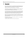
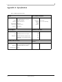
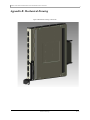
M2401G 24 Port 20Gb/s InfiniBand Switch
for the Dell M1000e Chassis User Manual
Rev 1.0
Mellanox Technologies
2
Copyright 2008. Mellanox Technologies, Inc. All Rights Reserved.
Mellanox Technologies, InfiniScale® is a registered trademark of Mellanox Technologies, Inc. All
other marks and names mentioned herein may be trademarks of their respective companies.
M2401G 24 Port 20Gb/s InfiniBand Switch
Document Number: 2948
Mellanox Technologies, Inc.
2900 Stender Way
Santa Clara, CA 95054
U.S.A.
www.Mellanox.com
Tel: (408) 970-3400
Fax: (408) 970-3403
Mellanox Technologies Ltd
PO Box 586 Hermon Building
Yokneam 20692
Israel
Tel: +972-4-909-7200
Fax: +972-4-959-3245
NOTE:
THIS INFORMATION IS PROVIDED BY MELLANOX FOR INFORMATIONAL PURPOSES ONLY AND ANY
EXPRESS OR IMPLIED WARRANTIES, INCLUDING, BUT NOT LIMITED TO, THE IMPLIED WARRANTIES OF
MERCHANTABILITY AND FITNESS FOR A PARTICULAR PURPOSE ARE DISCLAIMED. IN NO EVENT SHALL
MELLANOX BE LIABLE FOR ANY DIRECT, INDIRECT, INCIDENTAL, SPECIAL, EXEMPLARY, OR CONSEQUENTIAL DAMAGES (INCLUDING, BUT NOT LIMITED TO, PROCUREMENT OF SUBSTITUTE GOODS OR
SERVICES; LOSS OF USE, DATA, OR PROFITS; OR BUSINESS INTERRUPTION) HOWEVER CAUSED AND ON
ANY THEORY OF LIABILITY, WHETHER IN CONTRACT, STRICT LIABILITY, OR TORT (INCLUDING NEGLIGENCE OR OTHERWISE) ARISING IN ANY WAY OUT OF THE USE OF THIS HARDWARE, EVEN IF ADVISED
OF THE POSSIBILITY OF SUCH DAMAGE.
Rev 1.0
Mellanox Technologies
M2401G 24 Port 20Gb/s InfiniBand Switch for the Dell M1000e Chassis User Manual
3
Contents
Contents
3
About this Manual
4
Revision History
6
Chapter 1
Overview
7
Chapter 2
Installation and Basic Operation
8
Chapter 3
Chapter 4
2.1
Switch Platform Hardware Overview
2.1.1 InfiniBand Connectors
2.1.2 Switch Status Lights
2.2 Switch Platform Installation and Operation
2.2.1 Installation Safety Warnings
2.2.2 Mechanical Installation
2.2.2.1 Removing an Old Switch From the Chassis
2.2.2.2 Removing a Blank Cover Plate From the Chassis
2.2.2.3 Installing the Mellanox M2401G Switch Into the Dell Chassis
2.2.3 Power Connections and Initial Power On
2.2.4 InfiniBand Cable Installation
2.2.5 InfiniBand Optical Cable Installation
8
8
9
10
10
11
12
12
12
13
13
13
Management Tools Overview
14
3.1
14
Updating Firmware
Troubleshooting
15
Appendix A
Specification
16
Appendix B
Mechanical Drawing
17
Appendix C
EMC Certification Statements
18
Appendix D
InfiniBand Connector Pinout
20
Appendix E
Local Authorization Form
21
Mellanox Technologies
Rev 1.0
4
About this Manual
This manual describes the electrical and physical specifications of Mellanox Technologies’
M2401G 24 Port 20Gb/s InfiniBand Switch for the Dell M1000e Chassis.
Intended Audience
This manual is intended for users and system administrators responsible for installing and setting
up the switch platforms listed above.
The manual assumes familiarity with the InfiniBand® Architecture Specification.
Related Documentation
The documentation set accompanying the Mellanox M2401G includes the following:
Table 1 - Reference Documents
InfiniBand Architecture Specifica- InfiniBand architecture specification descriptions
tion Volume 1 Release 1.2.1 and
Volume 2 release 1.2.1
Mellanox Firmware Tools (MFT)
User’s Manual
Document # 2329
The MFT (Mellanox Firmware Tools) package is a set of firmware
tools. The manual supplied with this package provides an overview of
the firmware its installation and replacement. The MFT can be downloaded with its documentation at:
http://www.mellanox.com under “Firmware” downloads.
Online Resources
• Mellanox Technologies Web pages: http://www.mellanox.com
• Dell Support Web pages: http://support.dell.com
Conventions
Throughout this manual, the name M2401G and the term switch are used to describe the 24-port
20Gb/s InfiniBand switch for the Dell M1000e, unless explicitly indicated otherwise.
Trademarks and Service Marks
The following are Mellanox Technologies registered trademarks:
InfiniHost®, ConnectX®, and InfiniScale®
Rev 1.0
Mellanox Technologies
M2401G 24 Port 20Gb/s InfiniBand Switch for the Dell M1000e Chassis User Manual
5
Table 2 - Switch Products Covered in this User’s Manual
Product Number
Description
M2401G
24 Port 20 Gb/s unmanaged switch including 8 external ports for the Dell M1000e chassis.
This product does not require Advanced Management.
Mellanox Technologies
Rev 1.0
6
Revision History
Table 3 - Revision History Table
Date
Revision
Description
June 2008
Rev 1.0
First Draft
Rev 1.0
Mellanox Technologies
M2401G 24 Port 20Gb/s InfiniBand Switch for the Dell M1000e Chassis User Manual
7
1
Overview
This User’s Manual provides an overview of the M2401G 24-port 20Gb/s InfiniBand switch for the
Dell M1000e. The switch supports 16 switch ports towards the midplane and 8 external ports. In
addition to supporting passive copper InfiniBand cables, the external ports can provide power for
supporting active cables and optical cables through the use of media adapters.
The switch supports 16 switch ports towards the midplane and 8 external ports. In addition to supporting passive copper InfiniBand cables, the external ports can provide power for supporting
active cables and optical cables through the use of media adapters.
The switch platform comes pre-installed with all necessary firmware, and configured for standard
operation with InfiniBand fabric, and requires an InfiniBand compliant Subnet Manager running
from one of the hosts. All that is required for normal operation is to follow the usual precautions for
installation and connection from the switch to the HCAs or other switches. Once connected, the
Subnet Management software automatically configures and begins utilizing the switch.
Maintenance and configuration of the switch is done in-band over the InfiniBand fabric using the
Mellanox Technologies InfiniBand Administration (IBADM) tools package. This package provides
the ability to upgrade firmware and monitor the temperature, voltage, port utilization, and other status parameters in the switch.
Basic installation, hot-swapping components and hardware maintenance is covered in “Installation and Basic Operation” on page 8.
The M2401G switch has a Hot Swap controller and a PSOC Management IC
Mellanox Technologies
Rev 1.0
8
2
Installation and Basic Operation
2.1
Switch Platform Hardware Overview
Figure 1 shows the front panel view of the switch.
Figure 1: Switch Front Panel and Locking Mechanism
Locking Mechanism
2.1.1
8
7
6
5
4
3
2
1
Switch Status Lights
InfiniBand Connectors
InfiniBand connectivity has 8 CX4 microGiGa connectors through the front panel. The remaining
16 interfaces are through the AirMax Midplane Connector out the back of the switch. Figure 1
shows the front 8 ports.
Each of the front panel connectors has two LEDs located next to the connector. The green LED,
when lit, indicates that the InfiniBand driver is running and a valid physical connection between
nodes exists. The yellow LED when lit, indicates a valid data activity link, this is the logical link.
The yellow LED illuminates when the InfiniBand network is discovered over the physical link. A
valid data activity link without data transfer is designated by a constant yellow LED indication. A
valid data activity link with data transfer is designated by a blinking yellow LED indication. If the
LEDs are not active, either the physical link or the logical link (or both) connections has not been
established.
Figure 2: Physical and Logical Link Indications LEDs
LED Name
Physical Link - Green
Data Activity - Yellow
Blinking indicates Data Transfer
Constant on indicates no Data Transfer
Rev 1.0
Mellanox Technologies
M2401G 24 Port 20Gb/s InfiniBand Switch for the Dell M1000e Chassis User Manual
9
2.1.2
Switch Status Lights
The switch Status lights indicate whether the switch is receiving power from the chassis.
Figure 3: Indicator LEDs
Port number
8
This LED can be Blue or
Amber. If it is blinking
Amber it indicates a Fault.
See Table 4.
When both the blue and
green LEDs are lit this indicates that the IO Module is
on and ready.
Table 4 - IOM states and LED configurations:
LED
IOM State
Source
Blue
Amber
Green
OFF
N/A
OFF
OFF
OFF
BOOT_IN_PROGRESS
IOM
OFF
OFF
ON
NORMAL/ STACK_MASTER
IOM
ON
OFF
ON
STACK_SLAVE Stackable
IOM
OFF
OFF
ON
IOM_FAULT (self-diagnosed)
IOM
OFF
BLINK
1HZ
ON
IOM_FAULT (Misconfig or other CMC-detected fault)
CMC
OFF
BLINK
1HZ
OFF
MODULE_IDENTIFY
CMC
BLINK
1HZ
OFF
ON
Mellanox Technologies
Rev 1.0
10
2.2
Switch Platform Installation and Operation
Installation and initialization of the switch platform are straightforward processes, requiring attention to the normal mechanical, power, and thermal precautions for rack-mounted equipment. The
switch platform does not require any programming or configuration to operate as a basic InfiniBand switch and includes all of the necessary functionality to operate with external standard InfiniBand Subnet Management software.
This section describes the installation process and basic operation of the switch platform. Please
first read the warnings sub-section carefully before carrying on with installation procedures.
2.2.1
Installation Safety Warnings
1.
Installation Instructions
Read all installation instructions before connecting the equipment to the power
source.
2.
Over-temperature
This equipment should not be operated in an area with an ambient temperature
exceeding the maximum recommended: 50°C (122°F). Moreover, to guarantee proper
air flow, allow at least 8cm (3 inches) of clearance around the ventilation openings.
3.
Stacking the Chassis
The chassis should not be stacked on any other equipment. If the chassis falls, it can
cause bodily injury and equipment damage.
4.
During Lightning - Electrical Hazard
During periods of lightning activity, do not work on the equipment or connect or disconnect cables.
5.
Copper InfiniBand Cable Connecting/Disconnecting
Copper InfiniBand cables are heavy and not flexible, as such they should be carefully
attached to or detached from the connectors. Refer to the cable manufacturer for special warnings and instructions.
Rev 1.0
Mellanox Technologies
M2401G 24 Port 20Gb/s InfiniBand Switch for the Dell M1000e Chassis User Manual
11
6.
Rack Mounting and Servicing
When this product is mounted or serviced in a rack, special precautions must be taken
to ensure that the system remains stable. In general you should fill the rack with
equipment starting from the bottom to the top.
7.
Equipment Installation
This equipment should be installed, replaced, or serviced only by trained and qualified personnel.
8.
Equipment Disposal
Disposal of this equipment should be in accordance to all national laws and regulations.
9.
Local and National Electrical Codes
This equipment should be installed in compliance with local and national electrical
codes.
2.2.2
Mechanical Installation
These switches are hot pluggable. It is not necessary to power down the Dell Chassis to install a
new switch or to replace and old switch with a new one.
Mellanox Technologies
Rev 1.0
12
Figure 4: Rear View of the Dell M1000e Chassis
Latch Release Buttons
Locking Arm
2.2.2.1 Removing an Old Switch From the Chassis
1. Remove any locking cables or screws that secure the old switch into the chassis.
2. Disconnect all of the cables from the front of the switch to be removed.
3. Unlock the switch from the chassis by pushing the red latch release button.
4. Pull the locking arm down to a position perpendicular to the front of the chassis.
5. Pull the switch out of the chassis using the locking arm.
2.2.2.2 Removing a Blank Cover Plate From the Chassis
1. Remove any locking cables or screws that secure the blank cover plate into the chassis.
2. Unlock the blank cover plate by pushing the red latch release button.
3. Pull the locking arm down to a position perpendicular to the front of the chassis.
4. Pull the cover plate out of the chassis using the locking arm.
2.2.2.3 Installing the Mellanox M2401G Switch Into the Dell Chassis
Note: Make sure the Chassis is stable on a solid floor and that the Chassis is filled from the bottom up. This will keep the center of gravity as low as possible reducing risk of tipping.
Note: IOMs are to be installed from right to left.
1. Follow the instructions in Section 5.2.2.1 or Section 5.2.2.2 to remove an old switch or a Blank
cover plate.
2. On the new switch, push the red latch release button.
3. Pull the lever forward until the lever is perpendicular to the front panel.
4. Push the switch into the slot until the latching mechanism is against the bar.
Rev 1.0
Mellanox Technologies
M2401G 24 Port 20Gb/s InfiniBand Switch for the Dell M1000e Chassis User Manual
13
5. Push the lever on the latching mechanism up, making sure that the latching mechanism catches
the locking bar. The lever should now be parallel to the front panel.
6. Check the indicator lights to make sure the switch has power.
The installer should use a rack cable to support the mechanical and environmental characteristics of
a fully populated switch platform Chassis.
The rack mounting is designed to fit the Dell M1000e Chassis. Take precautions to
guarantee proper ventilation for air intake at the front of the chassis and exhaust at the
rear in order to maintain good airflow at ambient temperature. Cable routing in particular should not impede the air exhaust from the chassis.
2.2.3
Power Connections and Initial Power On
Caution: The switch platform will automatically power up when AC power is applied. There is no
power switch. Immediately upon closing the latching mechanism check to make sure that the
Power on to the Switch LED is lit.
2.2.4
InfiniBand Cable Installation
All cables can be inserted or removed with the unit power on. To insert a cable, press the connector
into the port receptacle until the connector is firmly seated. The GREEN LED indicator below each
port will light when the physical connection is established (that is, when the unit is powered on and
a cable is plugged into the port with a functioning port plugged into the other end of the connector).
After plugging in a cable, lock the connector using the latching mechanism particular to the cable
vendor. The YELLOW LED will light (non blinking indicating that no data is being transferred
yet). When a logical connection is made the yellow LED will blink signifying data is being transferred.
To remove, disengage the locks and slowly pull the connector away from the port receptacle. Both
LED indicators will turn off when the cable is unseated.
Care should be taken not to impede the air exhaust flow through the fan modules.
Note: Cable lengths should be used which allow for routing horizontally around to the side of the
chassis before bending upward or downward in the rack.
2.2.5
InfiniBand Optical Cable Installation
M2401G switches will work with optical cables and media adapters. Insert the media adapter into
the connector and then connect the optical cable to the media adapter. Make sure to close any locks
on the cables and media adapters. The GREEN LED indicator below each port will light when the
physical connection is established (that is, when the unit is powered on and a cable is plugged into
the port with a functioning port plugged into the other end of the connector). The YELLOW LED
will light (non blinking indicating that no data is being transferred yet). When a logical connection
is made the yellow LED will blink signifying data is being transferred.
To remove, disengage the locks and slowly pull the connector away from the port receptacle. Both
LED indicators will turn off when the cable is unseated.
Care should be taken not to impede the air exhaust flow.
Mellanox Technologies
Rev 1.0
14
Note: Cable lengths should be used which allow for routing horizontally around to the side of the
chassis before bending upward or downward in the rack.
3
Management Tools Overview
3.1
Updating Firmware
The switch is delivered with the latest Firmware. New firmware versions are issued as development
progresses. When new firmware becomes available Mellanox will notify customers, and the new
firmware image will be found on the Mellanox firmware download page.
You will need the Mellanox Firmware Tools package to update firmware for this switch. It can be
downloaded from:
http://www.mellanox.com/products/management_tools.php
Note: Don’t forget to set the flag for IBspark when you install the MFT kit.
Firmware for this switch can be updated by going to the site below and following the directions for
burning new firmware.
The latest firmware can be found at:
http://www.mellanox.com/support/firmware_download.php
Rev 1.0
Mellanox Technologies
M2401G 24 Port 20Gb/s InfiniBand Switch for the Dell M1000e Chassis User Manual
15
4
Troubleshooting
As soon as a switch is plugged in make sure that the power LED is on.
The power LED for the switch does not come on:
If the green Power LED is not on;
1. Check that the chassis has power.
2. Remove and reinstall the switch.
The link LED for the InfiniBand connector does not come on:
1. Check that both ends of the cable are connected.
2. Check that the locks on the ends are secured.
3. Make sure that the latest FW version is installed on both the HCA and the switch.
4. If media adapters are used check that the all connections are good, tight, and secure.
The activity LED does not come on:
Check that the Subnet Manager has been started.
The power LED for the switch shuts off:
1. Check that the there is adequate ventilation.
2. Make sure that there is nothing blocking the front or rear of the chassis and that the fan modules
are not blocked.
Mellanox Technologies
Rev 1.0
16
Appendix A: Specification
Table 5 - M2401G Specification Data
Physical
Power and Environmental
Size: 1.16” H x 10.04” D x 10.73” W
29.45 mm X255.20 mm X 272.50 mm
Weight: 1.5 Kg fully configured
Mounting: Vertically mounted rack
Maximum Power: 50W – M2401G
Temperature: 0 to 50 Celsius
Humidity: 10% - 90% non-condensing
Altitude:
Shock:
Vibration:
Power through: 1W per port
SerDes Speeds 10, 20 Gb/s per port
Connectors: microGiGaCN
Protocol Support
Regulatory Compliance
InfiniBand: Auto-Negotiation of 10Gb/s or 20Gb/s
Safety TBD
CB:
CE:
TUV:
QoS: 8 InfiniBand Virtual Lanes for all ports
Management: Baseboard, Performance, and Device management Agents for full InfiniBand In-Band
Management
EMC
Reliability, Availability and Serviceability
Features
Scalability and Performance
Switching Performance: Simultaneous wire-speed any port to any port
48K Unicast Addresses Max. per Subnet
Addressing: 16K Multicast Addresses per Subnet
Switching Capacity 960 Gb/s
Rev 1.0
Mellanox Technologies
M2401G 24 Port 20Gb/s InfiniBand Switch for the Dell M1000e Chassis User Manual
17
Appendix B: Mechanical Drawing
Figure 4 Mechanical Drawing of the Switch
Mellanox Technologies
Rev 1.0
18
Appendix C: EMC Certification Statements
C.1: FCC Statements (USA)
Class A Statements:
§ 15.21
Statement
Warning! Changes or modifications to this equipment not expressly approved by the party responsible for compliance (Mellanox Technologies) could void the user's authority to operate the equipment.
§15.105(a)
Statement
NOTE: This equipment has been tested and found to comply with the limits for a Class A digital device,
pursuant to Part 15 of the FCC Rules. These limits are designed to provide reasonable protection
against harmful interference when the equipment is operated in a commercial environment. This equipment generates, uses, and can radiate radio frequency energy and, if not installed and used in accordance with the instruction manual, may cause harmful interference to radio communications. Operation
of this equipment in a residential area is likely to cause harmful interference in which case the user will
be required to correct the interference at his own expense.
C.1.1 EN Statements (Europe)
EN55022 Class A Statement:
Warning
This is a class A product. In a domestic environment this product may cause radio
interference in which case the user may be required to take adequate measures.
C.1.2 ICES Statements (Canada)
Class A Statement:
“This Class A digital apparatus complies with Canadian ICES-003.
Cet appareil numérique de la classe A est conforme à la norme NMB-003 du Canada.”
Rev 1.0
Mellanox Technologies
M2401G 24 Port 20Gb/s InfiniBand Switch for the Dell M1000e Chassis User Manual
19
C.1.3 VCCI Statements (Japan)
Class A Statement:
(Translation - "This is a Class A product based on the standard of the Voluntary Control
Council for Interference by Information Technology Equipment (VCCI). If this equipment is
used in a domestic environment, radio interference may occur, in which case the user may be
required to take corrective actions.")
Mellanox Technologies
Rev 1.0
20
Appendix D: InfiniBand Connector Pinout
Figure 5: InfiniBand CX4 Connector Pinout
S10
S9
S12
S11
S14
S13
S16
IBtxIp(3)
IBtxOn(3)
IBtxIn(3)
IBtxOp(2)
IBtxIp(2)
IBtxOn(2)
IBtxIn(2)
IBtxOp(1)
IBtxIp(1)
IBtxOn(1)
IBtxIn(1)
IBtxOp(0)
IBtxIp(0)
IBtxOn(0)
IBtxIn(0)
S7
S8
Connector Pin
Number
Connector Pin
Name
S6
S1
IBtxIp(0)
S3
S2
IBtxIn(0)
S3
IBtxIp(1)
S4
IBtxIn(1)
S5
IBtxIp(2)
S6
IBtxIn(2)
S7
IBtxIp(3)
S8
IBtxIn(3)
S9
IBtxOn(3)
S10
IBtxOp(3)
S11
IBtxOn(2)
S12
IBtxOp(2)
S13
IBtxOn(1)
S14
IBtxOp(1)
S15
IBtxOn(0)
S16
IBtxOp(0)
G1-G6, G9, H1-H2
Signal Ground
G7
Sense-3.3V
G8
Vcc
S4
S1
S2
H1
G1
G2
G3
G4
G5
G6
G7
G8
G9
H2
Rev 1.0
Table 6 - Connector Pin Name and Numbe
Name Correspondence
S5
GND
GND
GND
GND
GND
GND
GND
Sense-3.3V
Vcc
GND
GND
S15
IBtxOp(3)
Mellanox Technologies
M2401G 24 Port 20Gb/s InfiniBand Switch for the Dell M1000e Chassis User Manual
21
Appendix E: Local Authorization Form
Mellanox Technologies
Rev 1.0
22
Rev 1.0
Mellanox Technologies