Download SAS PMII - Information Sheet
Transcript
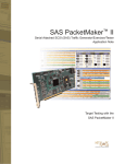
SAS PacketMaker™ II
Serial Attached SCSI (SAS), Serial ATA (SATA) Traffic Generator/Exerciser/Tester
Data Sheet
Versatile SAS/SATA Exerciser for Testing
1.5 & 3.0 Gb/s SAS Wide Ports and SATA
OVERVIEW
The Serial Attached SCSI (SAS)
PacketMaker II (PM2) is a versatile
SAS traffic generator capable of
initiator and target emulation with
an integrated SAS recorder. All
SAS protocols are supported
including SSP, STP and SMP. In
addition, PM2 supports SATA.
Users can work at the bit, byte,
Dword, packet or command level.
The product provides a complete
solution for test environments
ranging from R&D to production.
PRODUCT
DESCRIPTION
PM2 is a 64-bit PCI card that
operates in a 32 or 64-bit socket
in a Windows based PC (see
Figure 1).
Depending on the card model,
there is support for one, two or four
SAS phy links.
Each link capable of emulating a
host or device (see Figures 2 and
3 where two PM2 boards are
detected by the software). PM2
supports line signalling rates of up
to 3.0 Gb/s.
Two cards can be connected
together via a sync cable to
operate together to simulate up to
8 SAS links (on the four phy link
versions of the PM2).
Figure 1: PM2 board inside a PC (cut away view)
These links (see Figure 2) can also
be configured to work together or
separately for wide port operation.
This function provides test
engineers with the ability to have
synchronized control over multilane traffic and simulate SAS
components such as drives or host
bus adapters.
There are four ways to interact
with and control the PM2.
GUI WINDOWS APPLICATION
The first way is to use the GUI
application; the other way is to use
the API (Application Programming
Interface).
provides an easy to use interface
to create and send SAS packet
streams. It behaves like a word
processor for packets with drag
and drop, cut and paste, and insert
and delete functions.
A series of simple pull-down
menus provides all the options for
inserting new packets into a new
or existing stream for each link.
One Packet Stream Editor will be
opened for each link (in Link
Mode).
The Multi-Link Editor (see Figure
5) makes it easy to work with more
than one Stream Editor.
The GUI application (see Figure 4)
Figure 2: Configuring Links into Ports
Figure 3: Link Type Setup
2
u
v
w
l
l
l
Figure 4: Creating a Packet Stream/Three Tier Structure
Packet Stream Objects are laid out
horizontally with a three tier structure to
help with quick recognition of the
objects and easy understanding of their
structure. The top tier u describes the
protocol structure, such as a command
frame, Information Unit, or FIS type.
The second tier v provides the field
name. The last tier w displays the field
value. The colors for structures and
fields are all user-definable, so the
display can be changed to suit
individual preferences. On the left of
each object are colored indicators that
clearly show whether the object will be
sent, received or compared.
After inserting the packet, any of the
default field values can be modified.
Everything from changing how Align and
Sync Primitives behave, to
handshaking, credit management and
flow control management is
supported.
SAS Frames can also be altered to
change parameters in fields, add
additional fields or manipulate data
fields with pre-programmed data
patterns.
The GUI application allows for editing in
three modes. In the legal mode, only
valid structures and field values, as
Figure 5: Extreme SCSI
3
There is also another very unique
feature: the hardware data
generation and comparison. Data
patterns are generated, transmitted
and then checked. Errors are
recorded and logged.
The PM2 also has analysis
capabilities as it can monitor and
record packet information and
errors on the bus. If full SAS
decode and analysis capabilities
are required, the PM2 can be used
with a Bus Doctor™ Serial Attached
SCSI protocol analyzer.
C-BASED API
The second way to to create packet
streams and to operate PM2 is with
the C-based API. There are more
than 400 function calls available in
the API library. It supports all the
functionality available in the GUI
application but with more flexibility
due to the power of the C
programming language.
Figure 6: Link and Port Modes
defined by the Serial Attached
SCSI protocol specifications,
may be used.
In free form mode however,
illegal structures, invalid field
values, and other errors may be
set up. Field values can be
changed by simply doubleclicking on them; Coding or
Disparity Byte errors can be
added. A pop-up menu provides
the options for making the
changes. By right-clicking on any
field the user may delete it or
insert another, with all the
options made available through
simple menus.
In the view only mode, the user
can double-click on fields to
bring up the editor, but will only
be allowed to change display
options such as colors. Insertion
or deletion of packets is not
allowed.
Once the Packet streams are
created, they can be sent once,
looped for a certain number of
times, or looped infinitely.
Predefined errors can be
introduced into the SAS traffic at
any time during the send
process through software or a
manual pushbutton.
There are other powerful
features that are supported by
the PM2 and can be utilized
through the GUI. The PM2
supports Link and Port Mode (see
Figure 6). In Link mode, users
must insert the SAS addresses
into the Link Mode scripts.
However in Port mode, the
target SAS addresses are
automatically located allowing
for auto-insertion of these
addresses.
The PM2 also has the ability to
vary the OOB (Out-of-Band
signalling) timing; this unique
feature allows the duration and
frequency of COMINIT,
COMSAS and COMWAKE to be
easily adjusted to test initiator
and target responses to such
changes.
4
With the API, stand-alone programs
can be written and re-run over and
over again. PM2 comes bundled
with a set of ready to use
programs.
PACKETMAKER DEVELOPMENT
SOFTWARE
The PM2 comes bundled with the
PacketMaker Development
Software package (Model Number:
PM-DEV) (see Figure 7). This
package provides three SAS/SATA
focused test tools.
Extreme SCSI allows users to issue
any SCSI command to any
SAS/SATA device on any protocol.
It provides unparalleled functionality
in a tabbed interface for easy
navigation and enhanced useability.
Combine this with powerful utilities
such (as Format, Microcode
Download, Inquiry, Log and Mode
Page sense and modification),
media tools (copy, compare) and
canned tests (Command
Compliance, Reserved Bit Testing,
Random Command sequencing).
Operate on a single or multiple
devices.
Extreme Manufacturing helps users
test SAS/SATA peripheral. It
provides a powerful yet simple test
Phy Layer
Á OOB Burst Time
Á OOB Idle Time
Á OOB Sets
Á Phy Reset
Link Layer
Á BREAKs
Á Credit compliance
Á Connection tags
Á Primitives
Á Flow Control
The PacketMaker SVT employs a
simple to use graphical user interface
(see Figure 8) that allows the user to
select which tests to run, to launch the
tests and to display the results.
The tests are organized and grouped in
the left window u and are presented in
a tree view format. A user selects the
tests (or group of tests) to run by
clicking on the checkboxes to the left of
each test or test group heading.
Once the user has selected which tests
to run, he or she can click the start
button (triangle) on the menu bar to
begin running the test sequence.
Figure 7: PacketMaker Development Software
environment driven by a scripting
language. It can operate on any
number of drives simultaneously,
each running their own script. It
offers customizable logging, device
reports and system reports.
Scriptgen provides an easy to use
interface that allows for complex
test scripts to be created quickly.
Choose from canned tests, insert
individual SCSI commands, perform
complex looping or conditional
branching, launch executables, wait
for user input before continuing, the
list of features
PACKETMAKER SAS
VALIDATION TOOLS (SVT)
In addition, an optional
PacketMaker SAS Validation Tool
(SVT) (Model Number: PM-SVT) is
available (see Figure 8). This is a
protocol verification tool designed
for SAS targets and expanders.
capable of checking and validating
many different areas of conformance
to the SAS protocol specification.
There are tests for the Physical, Link,
and Transport layers of SAS targets
and expanders. Tests include aspects
of:
u
Special setup instructions for certain
tests are displayed in the top right
window v. The information instructs the
user to take certain steps before the
testing can proceed. For example, if the
user sees the message: connect a
target to link 1, the user must perform
this action before the PacketMaker SVT
continues running the rest of the tests.
l
l
The software test suite is a
Windows application that operates
with PM2. Consisting of several
hundred tests drawn from the SAS
specifications authored by the SCSI
Trade Association, the SVT is
l
Figure 8: PacketMaker SVT’s Main GUI Window
5
v
w
After each test is run, the results
are shown in the window
(w from previous page) on the
bottom right hand side. Tests that
passed are shown in green; tests
that failed are highlighted in red
with causes of the failure given.
During the running of any particular
test, the test name shows up in
blue color in the “select test”
window. The result window is a
scrolling text display.
The information shown in the
results windows is saved into a log
development and qualification time
requirements.
file. In addition, this file can be
printed.
Clear and concise help files
describe the purpose of each test
and the meaning of any specific
output when a failure occurs.
PM2 provides hardware and
software engineers with the power
to test their new devices or
controllers with virtually unlimited
combinations of Serial Attached
SCSI and Serial ATA protocol traffic.
This capability dramatically reduces
}
v
u
l
l
l
xy
w
l
l
z
l
l
l
l
l
l
l
l
l
|
u
v
w
x
y
x8 Sync Connector
Trigger in Pushbutton (future feature)
Status LEDs
Dynamic Error Pushbutton
Pod ID Display
6
z
{
|
}
Trigger Out
Trigger In (future feature)
SAS/SATA connectors
Mictor™ Connectors
l
{
l
APPLICATIONS
¢ Design and Development Testing
To verify that a SAS drive is operating correctly,
an actual host bus adapter (HBA) must be
available (the converse is true as well); hard
drive engineers can use PM2 to emulate a HBA
to test out their drive designs. The emulated
HBA can be programmed to send various packet
streams to the SAS drive. Responses received
back from the drive can be reviewed and
evaluated (see Figure 9).
//The following code, written in C, illustrates building and sending a SSP packet stream. The code builds a command
frame with a Read(6) command in the CDB. The code loops 1024 times, incrementing the LBA in the CDB each iteration.
#include <stdio>
#include “saspm.h” //PacketMaker API Header file for SAS
int main( )
{
unsigned long destAddress[2], long srcAddress[2];
PacketID open[1]; //to hold PacketID’s for Open frame
PacketID read6[2]; //to hold PacketID’s for Read(6)
void* podIds;
unsigned long maxPods, numPods, lbaID, size, i, j;
//Initialize SAS PacketMaker Library
InitSASPacketMaker(“C:\\PacketMaker\\DLL\\”,”C:\\PacketMaker\\pm.cfg”);
//Create SSP Open Frame Packet Sequence
destAddress[0] = 0x1734AC71; //Destination Address
destAddress[1] = 0xB5973814;
l
l
l
Figure 9: Sample Code Using the PM2 API
¢ Failure Analysis Troubleshooting
The PM2 records and saves all errors to a Event
Log file. The information stored includes the
type of error, link number, timestamp and other
useful data. This important feature can help
troubleshoot the cause of a SAS component
failure or malfunction (see Figure 10).
¢ Performance Analysis
Often it is necessary to check and verify
whether a SAS component is operating in
accordance to performance design during
development. This can be checked by using
PM2’s Burst Mode or continuous looping on the
same packet steam and observing and
evaluating the effects on the SAS component.
Latency values can be checked by reviewing the
timestamp information in the Activity Log.
Figure 10: Event Log shows Special Events such as Errors and Packet Miscompares
¢ Protocol Verification
The PM2 allows for easy alteration of any of the
fields in the packet stream, allowing different
protocol test scenarios to be easily set up (see
Figure 11). After the packet steam is transmitted,
the effects on the SAS component can be
examined and evaluated using the Activity and
Event logs.
¢ Manufacturing Tests
In a manufacturing test environment, there is a
critical need to reduce and limit the amount of
manual testing. The PM2’s C-based API is an
important tool in achieving test automation. It
enables re-use of previously developed test
programs so that they can be re-run over and over
again with minimal user intervention.
Figure 11: Double-Click on any Field to Edit or Change It
7
FEATURES
FULL DUPLEX SAS PORTS (1.5 & 3.0 Gb/s)
CARD SYNCHRONIZATION
Each card can generate and receive traffic on 1 to up to 4 SAS links (4 Phy
Link versions of card).
Two cards (4 Phy Link versions of card) can be synchronized to allow up to 8
links of traffic generation and reception.
PROTOCOL SUPPORT
Supports SSP, SMP, and STP (SATA) protocols.
SEQUENCE CONTROL PACKETS
Send packets, wait-for packets, branch packets, compare packets and more.
HOT-PLUG CONNECTIVITY
Simulates hot-plug events by forcing the Tx lines into common-mode
voltage.
CONTROL / COMMAND REGISTERS
Allows user to create and modify behavior packets.
DATA STREAM CREATION
Enables easy payload generation using several data streams, including
PROGRAMMABLE ERROR GENERATION
walking 1s, incrementing patterns, random patterns, and user files.
Capable of sending many types of bit and protocol errors. SAS Frames can
also be altered to change parameters in fields, add additional fields or
manipulate data fields with dynamic data.
DYNAMIC ERROR INJECTION
Allows user insertion of errors onto the SAS bus in real time. Errors such as
CRC, 10b and disparity can be inserted at anytime in the packet stream.
EVENT LOGGING
Logs several key events, such as Errors Transmitted and Data Miscompares.
ACTIVITY LOG
Contains the information received and transmitted on the links.
WAIT STATES
User may set the amount of time to wait before sending the next packet.
BUILT-IN DIAGNOSTICS
Verifies device functionality using built-in diagnostics such as a Power On
This can range from 26.67 ns to 8 hours.
Self test or Out of Band (OOB) Signaling. There is also a memory
initialization test to insure the memory on the PM2 is functioning properly.
PACKET DEVELOPMENT SOFTWARE
API TOOLKIT
MICTOR CONNECTORS
LINK AND PORT MODE
Simple to use GUI interface that easily allows creation and generation of
packet streams as well as bus monitoring.
Provides an API (Application Programming Interface) toolkit to generate
packet streams and send traffic using C functions.
Allows user to monitor the PHY transmit and receive 10b data paths.
Supports multi-link (Link Mode) and multi-port (Port Mode) packet streams.
In Port Mode, commands are queued across multiple SAS links using one of
five user selectable algorithms (i.e. round robin, random).
AUTO TARGET MODE
Useful when it is difficult or impossible to foresee and program in initiator
activity sequence. Provide initiator with layered control
8B/10B HARDWARE ENCODING/DECODING Performs time-sensitive 8b/10b encoding/decoding functions in the FPGA.
SAS OUT OF BAND FUNCTION
Can varying the timing and duration of SAS Out of Band (OOB) sequences
to test device ability to handle them.
8
SPECIFICATIONS
FLOW CONTROL
DIRECTIVES SUPPORTED
Send, Waitfor, Waitfor Branch, Compare, Multi-Compare, Config
FRAMES SUPPORTED
ADDRESS FRAMES SUPPORTED:
AF 0 Identify, AF 1 Open
SSP:
IU 01 DATA, IU 05 XFER_RDY, IU 06 COMMAND, IU 07 RESPONSE, IU 16 TASK
SMP:
IU 40 SMP_REQUEST, IU 41 SMP_RESPONSE
STP:
FIS 27 Register – Host to Device, FIS 34 Register – Device to Host, FIS A1 Set Device Bits – Device to Host, FIS 39 DMA Activate –
Device to Host, FIS 41 DMA Setup – Bi-directional, FIS 58 BIST Activate – Bi-directional, FIS 5F PIO Setup – Device to Host, FIS 46
Data – Bi-directional
OOB SIGNALS SUPPORTED
COMRESET / COMINIT, COMWAKE, COMSAS
PRIMITIVES SUPPORTED
NON-CONNECTION SPECIFIC:
AIP NORMAL, AIP RESERVED 0, AIP RESERVED 1, AIP RESERVED 2, AIP RESERVED WAITING ON PARTIAL, AIP WAITING ON
CONNECTION, AIP WAITING ON DEVICE, AIP WAITING ON PARTIAL, ALIGN 0, ALIGN 1, ALIGN 2, ALIGN 3, BREAK,
BROADCAST CHANGE, BROADCAST RESERVED 0, BROADCAST RESERVED 1, BROADCAST RESERVED 2, BROADCAST
RESERVED 3, BROADCAST RESERVED 4, BROADCAST RESERVED CHANGE 0, BROADCAST RESERVED CHANGE 1, CLOSE
CLEAR AFFILIATION, CLOSE NORMAL, CLOSE RESERVED 0, CLOSE RESERVED 1, EOAF, ERROR, HARD_RESET, NOTIFY
ENABLE SPINUP, NOTIFY RESERVED 0, NOTIFY RESERVED 1, NOTIFY RESERVED 2, OPEN_ACCEPT, OPEN_REJECT BAD
DESTINATION, OPEN_REJECT CONNECTION RATE NOT SUPPORTED, OPEN_REJECT NO DESTINATION, OPEN_REJECT
PATHWAY BLOCKED, OPEN_REJECT PROTOCOL NOT SUPPORTED, OPEN_REJECT RESERVED ABANDON 0, OPEN_REJECT
RESERVED ABANDON 1, OPEN_REJECT RESERVED ABANDON 2, OPEN_REJECT RESERVED ABANDON 3, OPEN_REJECT
RESERVED CONTINUE 0, OPEN_REJECT RESERVED CONTINUE 1, OPEN_REJECT RESERVED INITIALIZE 0, OPEN_REJECT
RESERVED INITIALIZE 1, OPEN_REJECT RESERVED STOP 0, OPEN_REJECT RESERVED STOP 1, OPEN_REJECT RETRY,
OPEN_REJECT STP RESOURCES BUSY, OPEN_REJECT WRONG DESTINATION, SOAF
SSP AND SMP:
ACK, CREDIT_BLOCKED, DONE ACK/NAK TIMEOUT, DONE CREDIT TIMEOUT, DONE NORMAL, DONE RESERVED 0, DONE
RESERVED 1, DONE RESERVED TIMEOUT 0, DONE RESERVED TIMEOUT 1, EOF, NAK CRC ERROR, NAK RESERVED 0, NAK
RESERVED 1, NAK RESERVED 2, RRDY NORMAL, RRDY RESERVED 0, RRDY RESERVED 1, SOF
STP:
SATA_CONT, SATA_DMAT, SATA_EOF, SATA_ERROR, SATA_HOLD, SATA_HOLDA, SATA_PMACK, SATA_PMNAK,
SATA_PMREQ_P, SATA_PMREQ_S, SATA_R_ERR, SATA_R_IP, SATA_R_OK, SATA_R_RDY, SATA_SOF, SATA_SYNC,
SATA_WTRM, SATA_X_RDY
USER-SPECIFIED
BIT ERRORS SUPPORTED
PROTOCOL ERRORS
SUPPORTED
10b Coding Error, 10b Disparity Error, Unknown Primitive, CRC Error
Framing Errors, Undersized Packets, Oversized Packets, Arbitration Failure and Retry
SSP:
Sending a NAK (CRC Error) primitive, not sending an ACK or NAK primitive, timeout errors
STP:
Sending SYNC primitives while receiving an STP packet, not sending HOLDA primitives when a HOLD primitive is received, simulating
an error with a received STP packet by sending an R_ERR primitive, not sending an R_RDY primitive when an X_RDY primitive is
received, sending an STP without first sending an X_RDY primitive
SMP:
Timeout Errors, unknown SMP Request, unknown SMP Response
9
HARDWARE SPECIFICATIONS (PM-SAS-1504Qe)
MECHANICAL
DIMENSIONS
Height: 5.7 inches (145 mm) (includes fingers)
Width: 11.4 inches (290 mm)
Weight: 0.65 lbs (295 grams)
CONNECTORS
64 bit 66 MHz PCI edge
4 Mictor connectors(1)
4 Standard SAS connectors(2)
BNC Trigger Out
BNC Trigger In (future feature)
POWER SPECIFICATIONS
PCI EDGE POWER REQUIREMENTS
3.3 V Supply:
Voltage . . . . . . . . . . . . . . . . . . . . . . . . . .3.3 V± 4%
Maximum Current (Iccmax) . . . . . . . . . .6A
5V Supply:
Voltage . . . . . . . . . . . . . . . . . . . . . . . . . .5 V ± 10%
Maximum Current (Iccmax) . . . . . . . . . .0.5A
DC SIGNALING
PCI SIGNALS
“3.3 V Card” found in the PCI 2.2 specification.
MICTOR CONNECTORS
LVCMOS 3.3V Per EIA/ JESD8-B standard
TRIGGER OUT
LVCMOS 3.3V Per EIA/ JESD8-B standard
AC TIMING
PCI SIGNALS
Per PCI 2.2 specifications
SAS CONNECTORS
Signaling Rate . . . . . . . . . . . . . . . . . . . . . .1.5 Gb/s
Clock Jitter . . . . . . . . . . . . . . . . . . . . . . . . .< 100 ps
MICTOR CONNECTORS(3) (Represent the Mictor AC timing characteristics for this product for monitoring parallel
10b Tx and Rx data for each link)
Transmit monitoring outputs
Full speed operation
QTn_TBC_
QTn_Tx, QTn_CM_
tsu
th
Receive monitoring outputs
Full speed operation
QTn_RBC_
ENVIRONMENTAL
SUBSYSTEM
QTn_Rx, QTn_RX_LOS_
tsu
th
tsu
tsu
th
tsu
th
th
tsu
th
Setup Time
Hold Time
Setup Time
Hold Time
Maximum Ambient Temperature: 50o C
Maximum Relative Humidity: 90%
Airflow: Per Intel® ATX specification
2nsec
2nsec
2nsec
2nsec
PCI SPECIFICATIONS
Width: Compatible with 32 or 64 bit wide PCI bus sockets and most PCI-X sockets
Speed: Compatible with 33 or 66 MHz bus speeds
Burst mode bandwidth:
Best case (66Mhz 64 bit PCI) . . . . . . . .~504 MBytes/s
Worst case (33Mhz 32 bit PCI) . . . . . . .~126 MBytes/s
Transfer Modes: Uses Single Read/Write and DMA Read/Write PCI transfers
(1): 1 Mictor Connector on PM-SAS-1501e.
(2): PM-SAS-1504e and PM-SAS-1504Qe only. PM-SAS-3001e has 1 and PM-SAS-3002e has 2 SAS connectors.
(3): Recommended analyzer clock setup is for positive or negative clock skew from data of 2 ns.
10
SYSTEM REQUIREMENTS
Á
Á
Á
Á
Á
Á
Windows® XP Professional or Windows 2000 Professional(A) operating system
Intel® Pentium® IV 2.0 GHz or faster processor
Minimum of 256 MB system RAM
50 MBytes of hard drive space for program files
32 or 64 bit PCI bus socket for insertion of PM2 board, operating at 33 or 66 MHz(B)
PC case capable of accommodating a PCI board 5.7” inches in height
Caution: If PacketMaker II is used in an open case, then airflow devices to maintain proper system cooling are required.
(A): Operation of multiple cards under Windows 2000 is not recommended. Please use Windows XP Professional instead.
(B): Most PCI-X sockets are capable of 66 MHz operations.
PRODUCT ORDERING INFORMATION
Model Number
Description
PacketMaker II Traffic Generators(1)
PM-SAS-1501e
PM-SAS-1504e
PM-SAS-1504Qe
SAS PacketMaker II, 1 Phy Link, (1.5 Gb/s)(2)
SAS PacketMaker II, 4 Phy Link, (1.5 Gb/s)(2)
SAS PacketMaker II, 4 Phy Link, H/W emulation, (1.5 Gb/s)(2)
PM-SAS-3001e
PM-SAS-3002e
SAS PacketMaker II, 1 Phy Link, (1.5 & 3.0 Gb/s)(2)
SAS PacketMaker II, 2 Phy Link, (1.5 & 3.0 Gb/s)(2)
PM-DEV
PM-SVT
PacketMaker Development Software Upgrade(3)(4)
PacketMaker II SAS Validation Tool(4)
Software
Model Number
RX-108P-SLIM
RX-108P-FIT
RX-108P-BUFF
Description (SAS Analyzers/Related Products)
USB-Controlled Analyzers
Bus Doctor RX, 108 channels, 64M events buffer
Bus Doctor RX, 108 channels, 128M events buffer
Bus Doctor RX, 108 channels, 256M events buffer
RX-252P-SLIM
RX-252P-FIT
RX-252P-BUFF
Bus Doctor RX, 252 channels, 64M events buffer
Bus Doctor RX, 252 channels, 128M events buffer
Bus Doctor RX, 252 channels, 256M events buffer
DR-SAS-3000
DR-SATA-3000
Serial Attached SCSI pod, (1.5 & 3.0 Gb/s)(5)
Serial ATA pod, (1.5 & 3.0 Gb/s)(5)
DR-SAS-3004
DR-SAS-30W4
4x SAS Pod, SATA Connectors, (1.5 & 3.0 Gb/s)(6)
Wide Port SAS Pod, MicroGiga Connectors (1.5 & 3.0 Gb/s)(6)
Bus Pods
(1): Includes: PM2 board, GUI control software, user manual and API.
(2): Includes PM-DEV.
(3): Provides 3 SAS/SATA focused PacketMaker II test tools that cut the development
process and time-to-market of new SAS/SATA devices.
a) Extreme SCSI issues any SCSI command to any device running the SAS/SATA
protocols.
b) Extreme Manufacturing test environment is designed for SAS/SATA peripheral
testing as well as manufacturing, DVT, ORT, incoming inspection and final
inspection.
c) Scriptgen is an easy to use tool for rapidly creating simple or complex test scripts.
(4): Requires a PacketMaker II Traffic Generator.
(5): Compatible with RX-108P Analyzers.
(6): Compatible with RX-252P Analyzers.
11
1389 Moffett Park Drive • Sunnyvale, CA 94089
Phone (US Toll Free): 888.746.6484
Phone Intl: 408.400.1000
Email: [email protected]
www.finisar.com
PMS 2745


