1
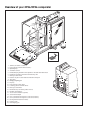
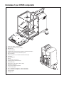
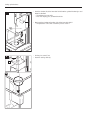
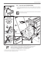
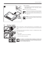
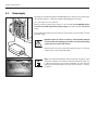
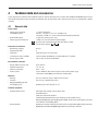
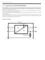
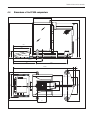
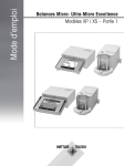
METTLER TOLEDO
XP56/XP26/XP505 Comparators
Supplementary Instructions to the Operating Instructions for XP Analytical Balances
Overview of your XP56/XP26 comparator
5
8
6
ww
w.m
t.
com
7
15
14
12
5
4
1
5
F
3
MET
TLE
2
23
1
RT
OL
EDO
4
3
3
F
1
2
3
4
5
6
7
8
9
10
11
12
13
14
15
16
17
18
19
20
21
22
23
Terminal (for details s. Section 4)
Display (Touch-sensitive “Touch Screen”)
Operating keys
SmartSens sensors
Handle/Coupling element for the operation of the outer draft-shield doors
Handle for operation of the outer draft-shield top door
Outer glass draft shield
Guide for top door of draft shield and handle for transport
Type name
Hanging weighing pan
Drip tray
Level indicator / Level sensor
Fastening point for anti-theft device
Inner glass draft shield
Removable clips for feeding cables or hoses
RS232C serial interface
Slot for second interface (optional)
Socket for AC adapter
Aux 1 (connection for “ErgoSens”, hand- or foot-switch)
Aux 2 (connection for “ErgoSens”, hand- or foot-switch)
Cooling element (based on model)
Leveling screw
Grid weighing pan
20
17
19
16
18
21
13
22
Overview of your XP505 comparator
5
8
6
ww
w.m
t.
com
9
XP2
04
7
15
14
12
5
F
10
11
4
3
MET
TLE
2
1
RT
OL
EDO
4
5
3
3
F
1
2
3
4
5
6
7
8
9
10
11
12
13
14
15
16
17
18
19
20
21
22
Terminal (for details s. Section 4)
Display (Touch-sensitive “Touch Screen”)
Operating keys
SmartSens sensors
Handle/Coupling element for the operation of the draft-shield doors
Handle for operation of the draft-shield top door
Glass draft shield
Guide for top door of draft shield and handle for transport
Type name
Grid weighing pan
Drip tray
Level indicator / Level sensor
Fastening point for anti-theft device
Intermediate shelf
Removable clips for feeding cables or hoses
RS232C serial interface
Slot for second interface (optional)
Socket for AC adapter
Aux 1 (connection for “ErgoSens”, hand- or foot-switch)
Aux 2 (connection for “ErgoSens”, hand- or foot-switch)
Cooling element
Leveling screw
20
17
19
16
18
21
13
22
Contents
Contents
1
Your XP56/XP26/XP505 comparator................................................................................................................ 5
1.1
1.2
1.3
1.4
Introduction.................................................................................................................................................................. 5
Contents of the Supplementary Operating Instructions.................................................................................................... 5
Safety first..................................................................................................................................................................... 5
Disposal....................................................................................................................................................................... 5
2
Setting up the balance..................................................................................................................................... 6
2.1
2.1.1
2.1.2
2.2
2.2.1
2.2.2
2.3
2.4
2.5
2.5.1
2.5.2
2.6
2.6.1
2.6.2
2.7
2.7.1
2.7.2
2.8
2.9
Unpacking and checking the delivered items.................................................................................................................. 6
Unpacking the balance................................................................................................................................................. 6
Checking the delivered items......................................................................................................................................... 8
Assembling the balance................................................................................................................................................ 9
Inner draft shield (XP56/XP26 comparator).................................................................................................................... 9
Outer draft shield (XP56/XP26/XP505)......................................................................................................................... 11
Selecting a location ................................................................................................................................................... 13
Power supply.............................................................................................................................................................. 14
Operating of the outer draft shield and the inner draft shield......................................................................................... 15
Outer draft shield........................................................................................................................................................ 15
Inner draft shield (XP56/XP26)..................................................................................................................................... 15
Setting the reading angle and location of the terminal.................................................................................................. 16
Setting the reading angle............................................................................................................................................ 16
Remove terminal and place close to the balance.......................................................................................................... 16
Transporting the balance............................................................................................................................................. 17
Transporting over short distances................................................................................................................................. 17
Transporting over long distances.................................................................................................................................. 17
Installing the ErgoClips................................................................................................................................................ 21
Installing the grid weighing pan cover.......................................................................................................................... 21
3
Special instructions for XP56/XP26/XP505 comparators................................................................................. 22
3.1
3.2
3.3
3.4
3.4.1
3.4.2
Location..................................................................................................................................................................... 22
Load the balance........................................................................................................................................................ 22
Settings for the outer and inner draft shield.................................................................................................................. 22
Settings for the comparators........................................................................................................................................ 24
Settings of the standard types: XP56/XP26/XP505 comparator...................................................................................... 24
Settings of the certified version: XP56/A, XP56/M, XP26/A, XP26/M comparator............................................................... 24
4
Technical data and accessories...................................................................................................................... 25
4.1
4.1.1
4.2
4.2.1
4.3
4.4
4.5
General data............................................................................................................................................................... 25
Explanatory notes for the METTLER TOLEDO AC adapter................................................................................................. 26
Model-specific data..................................................................................................................................................... 27
Zero-setting range and switch-on zero range for certified balances............................................................................... 28
Dimensions of the XP56/XP26 comparators................................................................................................................. 29
Dimensions of the XP505 comparators........................................................................................................................ 31
Accessories for the XP56/XP26/XP505 comparators..................................................................................................... 32
5
Index............................................................................................................................................................ 35
Your XP56/XP26/XP505 comparator
1
Your XP56/XP26/XP505 comparator
1.1
Introduction
Thank you for choosing a METTLER TOLEDO balance.
To operate the balance you should basically follow the Operating Instructions for Standard XP Analytical
Balances.
However, in these Supplementary Operating Instructions you will find information about how your balance
differs from the Standard XP Analytical Balances.
When working with the WeighCom application, use the operating instructions “WeighCom Application for XP
Comparator Balances” that were included with the delivery.
1.2
Contents of the Supplementary Operating Instructions
These Supplementary Operating Instructions contain the following information:
– Scope of delivery
– Assembling the balance
– Operating of the outer and inner glass draft shield
– Transporting the balance
– Installing the hanging weighing pan, installing the ErgoClip Basket micro and installing the grid weighing pan cover micro
– Instructions for XP56/XP26/XP505 comparators
– Technical data
– Accessories for XP56/ XP26/XP505 comparators
– Index
1.3
Safety first
Always operate and use your balance according to the instructions contained in the Standard Operating Instructions for XP Analytical Balances that were delivered with you balance. Instructions for operating the inner and outer draft shields are contained in these
Supplementary Operating Instructions.
The instructions for setting up your new balance must be strictly observed.
1.4
Disposal
In conformance with the European Directive 2002/96/EC on Waste Electrical and Electronic Equipment (WEEE)
this device may not be disposed of in domestic waste. This also applies to countries outside the EU, per their
specific requirements.
Please dispose of this product in accordance with local regulations at the collecting point specified for electrical
and electronic equipment.
If you have any questions, please contact the responsible authority or the distributor from which you purchased
this device.
Should this device be passed on to other parties (for private or professional use), the content of this regulation
must also be related.
Thank you for your contribution to environmental protection.
Setting up the balance
2
Setting up the balance
This chapter explains how to unpack your new balance, and how to set it up and prepare it for operation. When you have carried out
the steps described in this chapter, your balance is ready for operation.
2.1
Unpacking and checking the delivered items
2.1.1
Unpacking the balance
– Lift the cardboard box (a) out of the packaging and take out the Supplementary Operating Instructions that explain the further procedure for unpacking and assembling your balance.
a
Overview:
a Cardboard box with 2 sets (see next 2 pictures)
b Top packing cushion
b
c
d
e
f
g
c Set with inner draft shield, drip tray, and grid weighing pan micro
d Balance
e Lifting strap
f Terminal
Note: The terminal is connected to the balance by a cable!
g Bottom packing cushion
– Take the Operating Instructions and other documents (h) out of the cardboard box.
– Pull out set (i) with AC adapter, power supply cable, tweezers, and the set containing
hanging weighing pan, ErgoClip basket micro and grid weighing pan cover micro.
– Pull out set (k) with outer draft-shield doors and terminal support.
Set with:
– Hanging weighing pan and support (o)
– ErgoClip basket micro
• Support (m)
• Basket (n)
– Grid weighing pan cover micro (l)
Setting up the balance
– Use the lifting strap (e) to lift the balance out of the packaging carton.
– Unfasten lifting strap (e)
– Remove top packing cushion (b)
– Pull out set (c) with inner draft shield etc.
The terminal is connected to the balance by a cable, so only pull the
terminal just far enough out of the packing cushion to remove the protective cover.
– Carefully pull the terminal out of the bottom packing cushion and remove the protective
cover.
– Place the terminal on the front of the balance.
– Hold the balance by the guide or handle, hold the terminal firmly with your other hand,
and pull the balance and terminal together out of the bottom packing cushion.
Setting up the balance
– Place the balance with the terminal in the place where the balance will be used for
weighing.
– Remove the cover from the balance.
Please keep all parts of the packaging. This packaging guarantees best
possible protection of your balance for transportation (chapter 2.7).
2.1.2
Checking the delivered items
The standard scope of delivery contains the following items:
– XP56/XP26/XP505 comparator with terminal
– Set with outer draft shield and terminal support
– Set with inner draft shield, drip tray and grid weighing pan micro (XP56/XP26/XP505 comparator)
–
Set with (XP56/XP26/XP505 comparator)
• Hanging weighing pan
• Ergo Clip basket micro with support
• Grid weighing pan cover micro (attachment for grid weighing pan)
– AC adapter with country-specific power cable
– Tweezers
– Cleaning brush
– Protective cover for the terminal
– Production certificate
– CE declaration of conformity
– Supplementary Operating Instructions XP56/XP26/XP505 comparators (this document)
– Standard Operating Instructions for XP Analytical Balances
– Operating instructions “WeighCom Application for XP Comparator Balances”
Setting up the balance
2.2
Assembling the balance
2.2.1
Inner draft shield (XP56/XP26 comparator)
1
– Insert the front glass (A) of the inner draft shield.
Ensure the glass is centered and pushed in as far as the stop.
XP5
6
A
Hanging weighing pan or
2
Grid weighing pan
– Insert the drip tray (B).
Insert the drip tray from the side under
the upper 2 pins. The notches must
be positioned by the springs.
C2
2a
C
C1
When installing the hanging weighing pan, it
is advisable to wear
gloves.
B
– Insert the support (C1). Check that the
guide is correctly installed on both sides.
– Place the hanging weighing pan (C2) on
the swivel bearing by the support (C1).
After you have installed
the hanging weighing
pan (balance in operation) you must switch
the balance off and then
switch it on again (“On/Off” key).
– Insert the grid weighing pan (C) from
above.
Check that the grid weighing pan is correctly
hooked in on both sides.
– Insert the side window (D) of the inner draft shield.
1. At an angle of approximately 45 degrees to the final position, place the 2 black
clips on the back guide shaft.
2. Push the window up until you can swivel it in over the front glass.
.mt.
com
3
B
XP5
6
D
2
1
Setting up the balance
10
– Insert the window (D) of the inner draft shield into the guide of the front glas and
lower it to the floor.
• The window must run easily.
• Press the coupling pins (E) toward the inside.
4
E
– Now insert the window on the other side of the inner draft shield.
• The procedure is the same as shown in pictures 3 and 4.
D
5
– Put the glass cover (F) on.
G
– Insert the sealing cover (G).
F
5a
▼
Setting up the balance
11
6
2.2.2
1
Outer draft shield (XP56/XP26/XP505)
– Insert the outer top door of the draft shield at an angle (slightly less than 30 degrees)
into the guide positioned at the back, and swivel the draft-shield door carefully down
(see Fig. 6).
2
The handles (A) must be turned toward the outside to allow installation of
the side draft shield doors!
7
ww
w.m
t.co
m
2
XP5
6
4
3
A
1
A
– Insert the outer side doors of the draft shield according to the following instructions (see Fig. 7):
•
•
•
Insert the side door at an angle of approx. 30° into the 2 openings (see figure for details).
Check that the side door is correctly inserted as shown in the “View from the front”!
Swivel the side door up against the balance until it engages with a click.
The side door must run easily, otherwise it is not correctly inserted.
– Insert the second outer side door of the draft shield. The procedure is identical.
– Push the outer side doors completely to the back.
Setting up the balance
12
8
2
1
– Insert the front glass of the outer draft shield:
• In the bottom part of the balance at the front, move at an angle from the top toward the bottom until the two hooks of the front
glass of the draft shield lie on the rollers.
• Swivel the front glass of the draft shield up until it engages.
9
– Insert the terminal support:
• First lay the cable in the guide by the terminal support.
• Insert the terminal support into the opening of the front glass of the draft shield.
The terminal support must engage with a click.
Setting up the balance
13
– Mount the terminal:
• Place the terminal in the center of the support and push it
against the balance until it swivels slightly down at the front
by the terminal support.
Note: You can push the cable into the balance.
10
The balance and the terminal are not fastened together
by the terminal support! When transporting by hand,
always hold the balance and the terminal firmly (see
chapter 2.7).
F
ME
TTL
ER
TOL
E
DO
Note: You can also place the terminal free of the terminal
support anywhere around the balance where the length
of the cable allows.
F
2.3
Selecting a location
Choose a position which is stable, free from vibration, and as nearly horizontal as possible. The supporting surface must be able to bear the weight of the fully loaded balance
safely.
Pay attention to the environmental conditions (chapter 18.1 of the Operating Instructions
for XP Analytical Balances).
Avoid:
– Direct sunlight
– Strong drafts (e.g. from fans or air conditioning)
– Excessive fluctuations in temperature.
If the balance is not horizontal from the beginning, it will have to be
leveled during initial operation (see chapter 3.2 of the Operating Instructions for XP Analytical Balances).
Setting up the balance
14
2.4
Power supply
Your balance is delivered complete with an AC adapter and a country-specific power supply
cable. The AC adapter is suitable for all power supply voltages in the range:
100 – 240 VAC, -10/+15%, 50/60 Hz.
Check that the local power supply voltage is in this range. If it is not, DO NOT connect
the balance or the AC adapter to the power supply, and contact your METTLER TOLEDO
dealer.
Plug the AC adapter into the socket in the back of your balance (see illustration) and into
the power supply.
Important: Guide the cables so that they cannot become damaged
or interfere with the weighing process! Take care that the AC adapter
cannot come into contact with liquids!
After the balance has been connected to the power supply, it carries out
a self test and is then ready for operation.
A
A
B
Note: If the display field remains dark, even though the power supply
connection functions, first disconnect the balance from the power supply. Open the terminal by pressing the two buttons (A), then swivel the
upper part of the terminal open and check that the cable (B) is correctly
plugged in.
Setting up the balance
15
2.5
Operating of the outer draft shield and the inner draft shield
2.5.1
Outer draft shield
The outer draft shield of your balance can be adapted to the environmental conditions and your weighing style, as well as to the type
of weighing and loading.
The doors of the outer draft shield can be opened and closed either by means of the «K» key or with the “SmartSens” sensors (see also
chapter 3.3).
Try various different combinations by moving the 3 external handles up/inside and down/outside. We recommend you to set up the
outer draft shield so that it only opens on the side where the balance is loaded. Your balance then works faster, because there are fewer
troublesome currents of air than when both doors of the outer draft shield are opened together.
Note: It is best to make connections when the draft shield is closed.
For motorized door operation, the handles of the door to be opened must be engaged.
• Side doors: Handles turned toward the inside
• Top door: Handle down in horizontal position
2.5.2
Note:
“Manual” setting
Operating the door with the «K» key or “SmartSens” (see also chapter
3.3).
“Automatic” setting
The automatic door function opens and closes the doors automatically
whenever necessary (see also chapter 3.3).
Inner draft shield (XP56/XP26)
For motorized operation of the inner draft shield the coupling bolts (A) must be pressed
inward. The two side doors can be controlled separately.
You can also open the side doors of the inner draft shield only partway, with a choice of
25 %, 50 % or 75 % (see chapter 3.3).
A
Setting up the balance
16
2.6
Setting the reading angle and location of the terminal
2.6.1
Setting the reading angle
To change the reading angle, press in the two buttons (A) on the back of the terminal.The
top of the terminal can then be pulled up or down until it engages in the desired position.
A total of 3 setting positions are available.
A
2.6.2
A
Remove terminal and place close to the balance
The terminal is connected to the balance by a cable. So you can arrange your workplace optimally, the terminal can be removed from
the balance and placed separately.
You can also place the terminal separately (see illustration).
– Switch the balance off.
ww
w.m
– Carefully lift the terminal off the terminal support.
You can leave the terminal support on the balance or remove it.
t.com
– Pull the cable carefully out from the balance as far as possible.
XP56
– Place the terminal where you want it to be.
The cable can also be led out of the back of the balance. If working
this way would be convenient for you, call your METTLER TOLEDO
dealer who will adapt the balance for you.
F
MET
TLER
TOLE
D
O
F
Setting up the balance
17
2.7
Transporting the balance
Switch off the balance and unplug the cable of the AC adapter, as well as any interface cables, from the balance.
2.7.1
Transporting over short distances
If you wish to move your balance over a short distance to a new location, proceed as
follows:
ww
w.mt
With one hand, hold the balance by the guide for the top door of the draft shield. With your
other hand, hold the terminal. Carefully lift the balance and carry it to its new location.
(Observe the notes in chapter 2.3 regarding the choice of an optimal location).
.co
m
XP56
The terminal is not rigidly fastened to the balance, so you
must always hold the balance with one hand and the terminal
with the other.
Never lift the balance by the outer draft shield or the cooling
element, as this can cause damage!
F
MET
TLER
TOLE
DO
F
2.7.2
Transporting over long distances
If you want to transport or ship your balance over long distances, or if it is not certain that
the balance will be transported upright, use the complete original packaging.
6
ww
w.mt
.co
m
XP56
5
Disassemble the following parts:
3
– Lift the terminal (1) out of the terminal support and place it next to the support.
2
– Pull the terminal support (2) off the balance.
1
– Swivel the front glass (3) of the outer draft shield away from the balance.
– Carefully fold the side doors (4+5) against the respective handles and pull the side
doors out of the guide.
F
MET
TLER
TOLE
D
O
– Swivel the front of the top door (6) of the outer draft shield up and pull the door out
of the guide.
4
F
– Remove the sealing cover (7).
ww
7
w.m
– Lift the top glass (8) of the inner draft shield off.
t.com
– Pull both side doors (9 + 10) off.
• Pull up, turn to the side, and pull away.
8
9
10
13
– Lift the hanging weighing pan with the support (11), or the grid weighing pan, and lift
it out of the guide.
– Pull the drip tray (12) out at the side.
– Pull the front glass (13) up and away.
12
METT
LER
TOLE
D
O
11
Setting up the balance
18
Pack the outer draft shield and the terminal support (Items 3-6 and 2)
Place these parts in the compartments provided in the original packaging.
Note: We advise you to place a sheet of paper between the sides glasses
of the draft shield.
Pack the inner draft shield, the drip tray, and the grid weighing pan (Items 7-13)
Place these parts in the special compartments provided in the original packaging.
Pack the set with:
– Hanging weighing pan and support (o)
– ErgoClipBasket micro
• Support (m)
• Basket (n)
– Grid weighing pan cover micro (l)
Pack the 2 sets (i + k)
– Set (i) with AC adapter, power cable, tweezers, and the set with the hanging weighing
pan, ErgoClip Basket micro and grid weighing pan cover micro.
– Set (k) with the outer draft shield and terminal support.
Setting up the balance
19
– Push the guide of the upper draft shield door right to the front.
– Push the guide of the draft shield side doors right to the front.
– Fold the handles of the guides up/in.
These instructions must be followed exactly, otherwise the balance may
be damaged when inserting it into the packing cushions.
Note: For packing both the balance and the terminal,you have a protective
cover in which they were delivered. These are deliberately not shown in
the illustrations so you can see better how the individual items must be
positioned. However, we recommend you to use these protective covers.
– Place the terminal on the balance (see illustration) and carefully insert the balance
into the bottom packing cushion.
– Take the terminal and place it in front of the packing cushion on the table.
– Place the set in the packing cushion along with the inner draft shield (see picture).
– Insert the terminal into the packing cushion as shown in the illustration.
Setting up the balance
20
– Now put the top packing cushion in place, taking care to position it correctly.
– Pass the lifting strap around both packing cushions (see illustration) and tighten it
until it lies close against the packaging.
– You can now lift the packed balance by the lifting strap and insert it into the transport
carton.
– Place the packaging with the outer draft shield and AC adapter sets on the balance in
the transportation carton.
Setting up the balance
21
2.8
Installing the ErgoClips
To install the ErgoClip included in the delivery, or an optional ErgoClip, please proceed as follows:
– Remove the hanging weighing pan or grid weighing pan from the balance.
– Insert the support (A) for the “ErgoClip Basket micro”.
– Place the basket (B) on the guide (C) of the support.
C
A
After installing an ErgoClip the balance must be switched off and then
on again (“On/Off” switch).
Important to know!
B
If you do not switch the balance off before you do the installation, the ProFACT function
is not activated.
Reason: Addition of the ErgoClip causes the dead-load tolerance range of the balance
to be exceeded. The balance therefore does not activate ProFACT, so as not to interrupt
the assumed weighing operation.
When this status icon appears in the display, it means: “The balance wants
to execute ProFACT” but cannot.
2.9
Installing the grid weighing pan cover
– For the installation, remove the grid weighing pan from the weighing chamber.
– Gently press the cover onto the grid weighing pan.
– Replace the grid weighing pan with the installed grid weighing pan cover.
After an ErgoClip has been installed, the balance must be switched
of and then switched on again (“On/Off” key).
The reason is the same as explained in chapter 2.8 under “Important to
Know” and “Reason”.
Special Instructions for XP56/XP26/XP505 comparators
22
3
Special instructions for XP56/ XP26/XP505 comparators
To fully utilize the high resolution of the balance, some specific rules must be observed. These will enable you to obtain the best possible results.
3.1
Location
Take care to choose a good location (see also chapter 2.3).
We recommend you to operate the balance on a stone bench. Other surfaces can have a negative effect on the weighing performance.
3.2
Load the balance
Because of the high resolution of the balance, even minute differences of temperature or humidity can affect the result. Make sure that
the weighing chamber and hanging weighing pan are clean and that the weighing sample is acclimatized.
– Do not touch the reference and test weights with your hands.
– Always use suitable tweezers for loading and unloading the balance.
– The sealing cover in the top glass of the inner draft shield closes the opening in the glass through which you can pipette into a high
container.
• Do not use the sealing cover to lift the top glass of the draft shield.
3.3
Settings for the outer and inner draft shield
Operation of the draft shield doors is the same for the outer and the inner draft shield. You can set the door opening separately in steps
of 25 % to 100 %.
Depending on your settings for the coupling elements (see chapter 2.5), you determine which doors will be opened. Only open the
doors that are necessary for loading.
The factory setting for operation of the outer and inner draft shields is “Manual”. This means you must issue the command to open
the doors with the “K” key or with “SmartSens”.
Changing the settings for the draft shield doors:
C
Special Instructions for XP56/XP26/XP505 comparators
23
In this menu you can adjust the function of the doors of the outer- /and inner draft shield
to your requirements
The following options are available:
“Door Function”
To operate the doors manually, you press the «K» key or use SmartSens.
If you activate the Automatic door function, the doors of the outer and inner draft shields
open and close automatically whenever necessary.
Examples:
– When you press the «H» key, the doors open automatically to allow you to place
the tare weight on the pan.
– When you are prompted to place the adjustment weight on the pan while you are
adjusting the balance, the doors automatically open. As soon as you have placed the
weight on the pan, the doors automatically close again.
– The doors will close automatically whenever this is required to reach a stable weight
value.
– The doors open and close automatically during many work processes (e.g. piece
counting), depending on the current requirements of the application.
Factory setting: “Manual”
“Doorway and Doorway inner draft shield”
Doorway =
opening width of the outer draft shield
Doorway inner draft shield = opening width of the inner draft shield (XP56/XP26)
This setting allows you to define how wide the doors of the outer- and inner draft shield
open (automatically or manually). If you select the 100 % setting, the doors will open all
the way. If you select “25 %”, however, the doors will open only a quarter of the way. Two
other intermediate settings can be selected.
If your application allows it, you can reduce the opening of the doors. This shortens the
opening and closing times, making environmental influences (drafts) less bothersome.
Factory setting: “100 %”
Special Instructions for XP56/XP26/XP505 comparators
24
3.4
Settings for the comparators
3.4.1
Settings of the standard types: XP56/XP26/XP505 comparator
AutoZero:
Is switched off at initial operation and after a factory reset (resetting to the factory settings), but can be switched
on again when required.
When changing over to the “WeighCom” application, “AutoZero” is automatically switched off. When changing
back to the “Weigh” application, the previous status of “AutoZero” is restored.
When comparing masses, “AutoZero” must not be switched on, because it can distort the measurement
values.
ProFACT:
Is switched off at initial operation and after a factory reset (resetting to the factory settings). When comparing
masses, it is not advisable to switch “ProFACT” on.
3.4.2
Settings of the certified version: XP56/A, XP56/M, XP26/A, XP26/M comparator
AutoZero:
On certified balances,“AutoZero” must be switched on, but can be switched off if required.
ProFACT:
Is switched on at initial operation and after a factory reset (resetting to the factory settings), but can be switched
off when required.
When changing over to the “WeighCom” application, “AutoZero” is automatically switched off. When changing
back to the “Weigh” application, the previous status of “AutoZero” is restored.
External adjustment: Is not allowed for certified balances.
This function must be performed by a service technician.
Technical data and accessories
25
4
Technical data and accessories
In this chapter you will find the most important technical data for your balance. Accessories from the METTLER TOLEDO range increase
the functionality of your balance and open up additional areas of application. In this chapter you will find a list of the options currently
available.
4.1
General data
Power supply
• Power supply connector
with AC/DC adapter:
• Cable to AC adapter:
• Power supply to the balance:
11132070, PSU30A-3
Primary: 100-240V, -15%/+10%, 50/60Hz, 0.8A
Secondary: 12VDC ± 5%, 2.25A (with electronic overload protection)
3-core, with country-specific plug
12VDC ± 5%, 2.25A, maximum ripple: 80mVpp
Use only with a tested AC adapter with SELV output current.
Ensure correct polarity
Protection and standards
•
•
•
•
•
Overvoltage category:
Degree of pollution:
Protection:
Standards for safety and EMC:
Range of application:
Class II
2
Protected against dust and water
See Declaration of Conformity (separate brochure 11780294)
For use only in closed interior rooms
Environmental conditions
• Height above mean sea level:
• Ambient temperature:
• Relative air humidity:
• Warm-up time:
Materials
Up to 4000 m
10 – 30 °C
40% – 70 %
At least 12 hours after connecting the balance to the power supply.
The balance should not be switched into standby mode.
• Housing: • Terminal: • Hanging weighing pan and Grid weighing pan
Die-cast aluminum, plastic, chrome steel and glass
Die-cast zinc, chromed and plastics
Chrome-nickel steel (X5 Cr Ni 18 10)
Standard equipment
•
Delivered with balance:
• Documentation:
AC adapter with country-specific power cable
RS232C interface
Protective cover for the terminal
Feedthroughs for below-the-balance weighing and for antitheft device
Hanging weighing pan, grid weighing pan, ErgoClip Basket micro, grid weighing pan cover,
micro twizzers and cleaning brush
Operating instructions XP Analytical Balances, these Supplementary Operating Instructions,
Operating instructions WeighCom Application and production certificate
Technical data and accessories
26
4.1.1
Explanatory notes for the METTLER TOLEDO AC adapter
METTLER TOLEDO balances are operated with a certified external power supply which conforms to the requirements for Class II double
insulated equipment and it is not provided with a protective earth connection but with a functional earth connection for EMC puposes.
Information about conformance of our products can be found in the brochure “Declaration of Conformity” which is coming with each
product or can be downloaded from www.mt.com
Consequently an earth bonding test is not required. Similarly it is not necessary to carry out an earth bonding test between the supply
earth conductor and any exposed metalwork on the balance.
In case of tetsting with regard to the directive 2001/95/EC the power supply and the balance has to be handled as Class II double
insulated equipment.
Because mass comparators can be sensitive to static charges a leakage resistor, typically 10kΩ, is connected between the earth
connector and the power supply output terminals. The arrangement is shown in Fig.1. This resistor is not part of the electrical safety
arrangement and does not require testing at regular intervals.
Equivalent circuit diagram:
Plastic Housing
Double Insulation
P
AC
Input 100…240V AC
N
Output 12V DC
DC
10 kΩ coupling resistor for
electrostatic discharge
E
Technical data and accessories
27
4.2
Model-specific data
Technical data (limit values)
Model
XP26 Comparator
XP56 Comparator
XP505 Comparator
Maximum load
22 g
52 g
520 g
Readability
0.001 mg
0.001 mg
0.01 mg
Repeatability (measured at)
0.0015 mg (20 g, ABA)
0.003 mg (50 g, ABA)
0.035 mg (500 g, ABA)
Repeatability at low load (measured at)
0.0007 mg (1 g)
0.0007 mg (1 g)
0.01 mg (50 g)
Linearity
0.006 mg
0.020 mg
0.1 mg
Eccentric load deviation (measured at)
0.00 mg (20 g)
0.00 mg (50 g)
0.2 mg
Sensitivity offset
4 x 10 ∙Rnt
2.5 x 10 ∙Rnt
2.5 x 10 –6∙Rnt
Sensitivity temperatur drift
1 x 10 – 6/°C∙Rnt
1 x 10 – 6/°C∙Rnt
1 x 10 – 6/°C∙Rnt
Sensitivity stability
1 x 10 /°C∙Rnt
1 x 10 /°C∙Rnt
1 x 10 – 6/°C∙Rnt
Interface update rate
23 /s
23 /s
23 /s
Balance dimensions (W x D x H) [mm]
263 x 487 x 322
263 x 487 x 322
263 x 487 x 322
Usable height of outer draft shield
235 mm
235 mm
235 mm
Usable height of inner draft shield with grid weighing pan
111 mm
111 mm
–
Usable height with hanging weighing pan
72 mm
72 mm
–
Dimensions grid weighing pan (W x D) [mm]
40 x 40
40 x 40
78 x 73
Dimensions hanging weighing pan [mm]
∅ 35
∅ 35
–
Weight
11.5 kg
11.5 kg
10.0 kg
XP505 Comparator
2)
–6
–6
–6
–6
Typical data for determination of the measurement uncertainty
Model
XP26 Comparator
XP56 Comparator
Stabilization time
3.5 s
3.5 s
Repeatability (sd)
0.0007 mg + 4x10 ∙Rgr
1)
–8
Differential nonlinearity (sd)
1.2x10
–13
g∙Rnt
5s
0.0007 mg + 4x10 ∙Rgr
–8
3x10
–13
g∙Rnt
0.008 mg + 4.5x10– 8∙Rgr
5x10–12 g∙Rnt
Differential eccentric load offset (sd) 4)
3 x 10 – 7∙Rnt
4 x10 – 7∙Rnt
5x10 – 7∙Rnt
Sensitivity offset (sd)
1x 10 ∙Rnt
1.2 x10 ∙Rnt
5x10 – 7∙Rnt
2)
–6
Minimum weight (according to USP)
Minimum weight (U=1%, 2 sd)
3)
4)
1)
2)
1) 3)
1) 3)
–6
2.1 mg + 1.2 x10 – 4 ∙Rgr
3.6 mg + 3 x10 – 4 ∙Rgr
24 mg + 1.4x10 – 4 ∙Rgr
0.14 mg + 8 x10 ∙Rgr
0.24 mg + 2 x10 ∙Rgr
16 mg + 9x10 –6∙Rgr
–6
–5
Valid for compact objects
After adjustment with built-in reference weight
The minimum weight can be improved by the following measures:
– Selecting suitable weighing parameters
– Choosing a better location
– Using smaller taring containers
Only with the grid weighing pan. With the hanging weighing pan the value = 0 (zero).
sd =
Rgr =
Rnt =
a =
Standard deviation
Gross weight
Net weight (sample weight)
Year (annum)
Data shown as typical are reference values for calculation of the expected measurement uncertainty. The actual measurement performance may be affected negatively
or positively by the place of use and/or the settings.
Technical data and accessories
28
4.2.1
Zero-setting range and switch-on zero range for certified balances
Zero-setting range
Certified balances can only be set to zero within ± 2% of the maximum capacity. Outside this range, the balance must be tared.
Switch-on zero range
Certified balances can only be started up when the load is within the range –1 g… +10 g relative to the switch-on zero value (balance
with empty weighing pan).
Technical data and accessories
29
4.3
Dimensions of the XP56/XP26 comparators
With hanging weighing pan
36
58
57
133
72
155
296
300
∅22
322
150
53
181
252
486.5
11
80
263
186
150
195
241
85
∅ 35
Technical data and accessories
30
With grid weighing pan
296
111
300
∅22
322
150
155
36
58
58.5
133
53
181
252
486.5
11
80
263
186
150
40
195
241
85
40
Technical data and accessories
31
4.4
Dimensions of the XP505 comparators
322
296
300
150
155
58
60
133
233.5
252
150
195
241
186
11
78
486.5
73
263
181
Technical data and accessories
32
4.5
Accessories for the XP56/XP26/XP505 comparators
You can increase the functionality of your balance with accessories from the METTLER TOLEDO range. The following options are available:
Printer
RS-P42: Printer with connection cable RS232, for recording results
00 229265
BT-P42: Bluetooth printer with wireless connection to the balance
11132540
Optional interfaces
RS232C (second RS232C interface)
11132500
LocalCAN: Connection for max. 5 devices with LocalCAN connection
11132505
MiniMettler (downward compatibility to older devices from METTLER TOLEDO)
11132510
PS/2: For connection of commercially available keyboards and barcode readers
11132520
BTS (Bluetooth): For wireless connection to a BT-P42 printer, BT-BLD auxiliary display or to a PC
11132535
BT option: For wireless connection for max. 6 different devices
11132530
Ethernet: For connection to an Ethernet network
11132515
e-Link IP65 EB01: Ethernet connection to the e-Link network with IP65 protection
11120003
Cable for RS232C interface (for standard interface or option 11132500)
RS9 – RS9 (m/f), connection cable for computer or RS-P42 printer, length = 1 m
11101051
RS9 – RS25 (m/f), connection cable for computer (IBM XT or compatible), length = 2 m
11101052
RS9 – RS9 (m/m), connection cable for devices with DB9 socket (f), length = 1 m
21250066
Cable for LocalCAN interface (option 11132505)
LC-RS9: Cable for connecting a PC with RS-232C, 9-pin, length = 2 m
00229065
LC-RS25: Cable for connecting a printer or PC with RS-232C, 25-pin (m/f), length = 2 m
00229050
LC-RS open: Cable for connecting the MT ComBus system, length = 4 m
21900640
LC-CL: Cable for connecting a device with METTLER TOLEDO CL interface (5-pin), length = 2 m
00229130
LC-LC03: Extension cable for LocalCAN, length = 0.3 m
00239270
LC-LC2: Extension cable for LocalCAN, length = 2 m
00229115
LC-LC5: Extension cable for LocalCAN, length = 5 m
00229116
LC-LCT: Cable branch (T-connector) for LocalCAN
00229118
Cable for MiniMettler interface (option 11132510)
MM – RS9f: RS232C connection cable for MiniMettler Interface, length = 1.5 m
00210493
Auxiliary display (displays only the weight value and unit, if defined)
RS/LC-BLD: Auxiliary display with RS232 & LC connection and external power supply, with table stand
00224200
RS/LC-BLDS: Auxiliary display with RS232 & LC connection for table stand or balance stand
11132630
BT-BLD bluetooth auxiliary display for wireless connection to balance with BTS interface, with table stand
11132555
LC-AD: Auxiliary display, active, with table stand
00229140
LC-ADS: Auxiliary display, active, with table stand
00229150
Technical data and accessories
33
Input/output devices
ErgoSens: programmable sensor for hands-off operation, cable length = 0.6 m
11132601
Foot switch: Programmable key with cable, length 2 m
11106741
LC-FS: Foot switch with adjustable function for balances with LocalCAN interface
00229060
LC-IO: Relay interface with digital inputs and outputs, switch eight different devices on and off
21202217
LC switchbox; connect up to three balances with LocalCAN interface to a printer
00229220
Barcode reader RS232
21900879
• AC adapter 230V EUR
21900882
• AC adapter 115V USA
21900883
Antistatic kit
For discharging electrostatically charged weighing containers and weighing objects (single point ionizer).
11107761
Optional second single point ionizer
11107762
Universal antistatic kit, complete (U ionizer)
11107767
Optional U ionizer for universal antistatic kit
11107764
SE kit
XP-SE kit: Separate evaluation electronics for weighing in contaminated environments
11106743
Extension cable between cell and evaluation electronics, length 0.6 m
00211535
Extension cable between cell and evaluation electronics, length 5 m
00210688
ErgoClips
ErgoClip Basket micro (basket for small weighing objects)
11107889
ErgoClip Flask micro (for volumetric flask)
11107879
MinWeighDoor micro
MinWeighDoor micro (ideal for use with ErgoClip Flask micro)
11107869
Software
MC Link (Windows® software for comparative weighings)
11116504
LabX pro balance (network capable solution for management of weighing data)
11120301
LabX light balance (management of weighing data made easy)
11120317
LabX direct balance (simple data transfer)
11120340
Freeweigh. Net
21900895
Diverses
IP54 Protective housing for AC adapter
11132550
Wall fixture for terminal
11132665
Fixture for terminal or printer, mounting on balance
11106730
Terminal extension cable, length = 4.5 m
11600517
Protective cover for terminal
11132570
Transport case
11106729
Anti-theft device (steel cable)
11600361
Technical data and accessories
34
Reference weights
Reference weight E1 20 g SCS certified
00159131
Reference weight E1 50 g SCS certified
00159141
Reference weight E1 500 g SCS certified
00159171
Index
35
5
Index
A
O
AC adapter 14, 25, 26
Accessories 32
Antistatic kit 33
Assembling the balance 9
Automatic door function 23
Operating of the outer draft shield and the inner 15
Outer draft shield 15
Overview 2, 3
P
Cable 32
Certified balances 28
Contents of the Supplementary Operating Instructions 5
Pack 18
Power supply 14, 25
Power supply voltages 14
Printer 32
Protection and standards 25
D
R
Dimensions 29, 31
Display field remains dark 14
Disposal 5
Door Function 23
Doors 23
Doorway 23
Reference weights 34
Remove terminal 16
C
S
Grid weighing pan 9
Grid weighing pan cover 21
Safety 5
Self test 14
Settings for the comparators 24
Settings for the outer and inner draft shield 22
Settings of the certified version 24
Settings of the standard types 24
Setting the reading angle 16
Setting up 6
Special instructions for XP56/XP26/XP505 comparators 22
Standard scope of delivery 8
H
T
Hanging weighing pan 9
Technical data 25
Terminal 13, 16
Transporting over long distances 17
Transporting over short distances 17
Transporting the balance 17
E
Environmental conditions 25
ErgoClips 33
G
I
Inner draft shield 15
Installing the ErgoClips 21
Installing the grid weighing pan cover 21
Interfaces 32
L
Load the balance 22
Location 13, 22
Location of the terminal 16
M
Materials 25
Model-specific data 27
U
Unpacking the balance 6
Leer
Leer
To protect your METTLER TOLEDO product’s future:
METTLER TOLEDO Service assures the quality, measuring accuracy
and preservation of value of all METTLER TOLEDO products for years
to come.
Please send for full details about our attractive terms of service.
Thank you.
*11780862*
Subject to technical changes and to changes in
the accessories supplied with the instruments.
© Mettler-Toledo AG 2008
11780862A Printed in Switzerland 0802/2.12
Mettler-Toledo AG, Laboratory & Weighing Technologies, CH-8606 Greifensee, Switzerland
Phone +41-44-944 22 11, Fax +41-44-944 30 60, Internet: http://www.mt.com