Download User Manual rev 1.01 1/2/2013 INSTRUCTION
Transcript
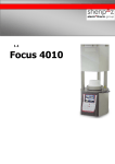
[email protected] | Tel: +972 (0)-9-8825473 INSTRUCTION MANUAL UNIPRESS porcelain press furnace User Manual rev 1.01 1/2/2013 | Fax: +972 (0)-9-8614474 Warning ATTENTION! You have available one of the most precise dental ceramic furnaces equipped with a heating muffle made of quartz glass or ATC from the original manufacturer of this technology with an experience of more than 25 years. IN ORDER TO PRESERVE THIS PRECISION AT ALL TIMES, PLEASE BE SURE TO ATTENTIVELY READ THE FOLLOWING INSTRUCTIONS PRIOR TO USING THE FURNACE! Prior to carrying out maintenance work on the furnace or in case of mechanical failure, be sure to first make dead the device. To do so, switch the main switch (POWER) on the back of the furnace to OFF and pull the power-supply plug. Only qualified and experts recommended by the furnace supplier should open the furnace. All pumps connected to the furnace and those which may have been supplied by the manufacturer or by other suppliers must be provided with the CE symbol. In case of doubt, consult your furnace supplier. Be sure to only use ceramics and alloys that are provided for being used in dental furnaces. Certain parts of the furnace may run very hot during operation. Be sure to use the supplied twizzers. Do not attempt to open the furnaces without authorization since this will void the guarantee. For any necessary repair and maintenance work, consult your Shenpaz device servicing center. In case of a necessary replacement of fuses, proceed as follows: 1) Pull the power-supply plug. 2) Replace the fuse. 3) Be sure the correct safety fuse parameter is indicated on the spare fuse. 2|Page In case of an external power failure and when the furnace is in operation, proceed as follows: 1) Pull the power-supply plug. 2) Lower the support. To do so, insert the supplied crank into the hexagonal screw on the back of the furnace. ATTENTION! When operating the furnace a Ceramic table or pressure table must always be on the lift tray! ATTENTION! Take out the furnace with both hands. To do so, hold the bottom of the furnace with one hand and the top side with the other hand. ATTENTION! Do not pull out the furnace by its support in order to avoid damages. 3|Page Table of Contents 1. Installation 5 2. Switches and Keys 6 3. Functions and Displays 10 4. Special Functions 16 5. Diagnosis Menu 18 6. Technical Data 20 7. Putting out of Commission and Disposal 21 8. Distribution and Technical Service 23 9. Pre-installed Programs / Overview 24 4|Page 1. Installation Unpacking: Check the packaging of the furnace on any visible damage. Check whether all components are present by means of the listing below: Ceramic Table Power cord Pump hose 8A fuse (for the heating) 5A fuse (for the pump) Instruction manual Twizzers Emergency 6-mm wrench Additional Components of UNIPRESS : Pressure Table Cylinder press system, including 2 dies Plunger Setting Up: Place the furnace on a level surface and keep a distance of at least 10 cm. Keep combustible objects away from the furnace. Do not expose the furnace to direct sunlight in order to avoid possible damages of the LCD display. Protect the furnace from strong air circulation (such as ventilators), since this may result in fluctuations of the temperature display when opening the programs chamber. Power Supply: Connect the furnace to a grounded power socket. Be sure the parameters are in conformity with the electrical specifications of the UNIPRESS / model. • Your furnace is equipped with the latest software recovery system. In case of electrical shut down, your cycle will fully be recovered within a temperature decrease not exceeding 150ºC degrees. For a temperature decrease more than this value, the cycle will be aborted to avoid unnecessary firing. Vacuum Pump: Connect the power-supply plug and vacuum tube to the furnace. 5|Page Compressed Air: Connect the furnace to a compressed-air system by means of a compressed-air tube. The maximum in-feed pressure should not exceed 8-10 bar. In order to avoid damages on the furnace, the compressed air must be absolutely dry. 2. Switches and Keys Master Switch: The master switch is on the back of the furnace. Put the switch on ON. An acoustic signal will sound. Stand By/ On/Off Press Stand By to switch on the furnace. The program overview display window appears. IMPORTANT NOTE: The furnace must never be heated without its programs stand or pressure stand, respectively! Alphanumeric Keys Press these keys to enter parameters, the program numbers to be selected, the program names and to directly select single menu sub-entries. 6|Page Arrow Keys Control of lift (press long, or release only after peep sound, respectively) In the program overview display window: Selection of parameters to be entered or to be modified (press short) On the display, “Program List”: Selection of desired program In Menus: Selection of sub-entries MENU Key Press this key to go to the main menu. START Key Press this key to start the selected program. STOP Key Press this key twice to abort the currently running program (safety query). The programs chamber opens up. 7|Page COPY/HoldKey Press this key to intervene in a currently running program. This function („Hold“ key) is used to modify a currently running program. The parameters imminent in the current program will be changed once. The saved program remains unchanged. Proceed as follows: 1. Press the key (the program is interrupted) 2. Press the arrow and numeric keys to modify the program parameters. 3. Press ENTER to confirm. 4. Press this key again to resume the program. In idle state, the programs can be copied onto another program digit („COPY“ key). To copy an existing program, proceed as follows: 1. Select the program to be copied 2. Press the key. 3. Enter destination with numeric keys. 4. Press ENTER to confirm. Program Key After pressing this key, a program number can directly be selected; to do so, press the numeric key/ENTER. Switching to Graphic Representation and back Press this key to switch the display into a graphic representation. Press this key again to display a list. 8|Page F2 – Special Function Press this key in standby mode to activate the diagnosis mode. Press this key in the operation mode to call up the Name Editor. F1 – Help Key Press this key to call up a help text with reference to the current program. Key for Subsequent Programs (Soldering in the Furnace) Press this special key to: conveniently carry out a subsequent soldering after soldering in the furnace activate the automatic pressing mode 9|Page 3. Functions and Displays Program Overview Display Window This display is divided up in different sections: The status section is on the left side of the All display and shows the respectively current displayed on the right display page. parameters of the program are status. The vacuum parameters are displayed between two Horizontal lines and in the center of the display. Graphic Representation This picture shows a graphic representation of the currently running program and its parameters. When selecting a pressing program (UNIPRESS), the pressure level will be indicated here as well. Normal's program Pressing program 10 | P a g e Modes On UNIPRESS, the program digits 1 – 200 are available for the „programs” mode. Unlike the above, the program digits 180 – 200 on UNIPRESS are configured in advance for the „pressing“mode. Choice of Programs and Starting the Program Press the PROG key and select the program numbers by means of the numeric keys. Press ENTER to confirm your selection. Press the START key to start the program now. The current work progress will flash when the program is running. Once the program is completed, the programs chamber opens up and gives off an acoustic sound. The current programs program will end a few seconds later. You may also chose a program from the list of the programs press enter on the chosen program press enter the program will be upload automatically and ready to use, from this screen you may activate the program by pressing the start button or modified the parameter before the Start of the program Pre-heating Program Important note: During transportation, storage and non-use, the isolation may absorb humidity. In order to avoid damages on the vacuum and heating system and in order to always obtain reproducible programs results, the user should always run the pre-heating program (program digit 01) at first and in the beginning. This is always recommended if the furnace has been completely cooled down after operation. 11 | P a g e Editing the Program Name In order to edit the program name, press F2 in the program overview display window. Then enter the program name by means of the alphanumeric keys. The cursor will be shifted by way of pressing the arrow keys (right/left). Press the START key to shift between the upper and lower case. Editing the Program Contents 1. Press the arrow keys to select the parameters. 2. Press the numeric keys to enter the parameters. 3. To edit further parameters, follow the steps 1 and 2 above. 4. Press ENTER to confirm. Vacuum values up to 755 mmHg = pump is running when needed 760 mmHg = permanent operation of pump If non-convertible parameters are entered, If reference errors occur, the digits an acoustic signal will sound and the concerned will be highlighted and a prompt automatic help program suggests possible request for correction appears. parameters. Menu Press the MENU key to go to the main menu with its three sub-entries: 12 | P a g e Press the numeric keys to directly make your selection. 1. Program List: This list shows an overview over all programs/pressing programs. Press the arrow keys to scroll through the list. You may also directly select a program through pressing the numeric keys. The program highlighted through this can optionally be started directly by way of pressing the START key or be called up by way of pressing the ENTER key for viewing/editing. The program digits 180 to 200 are provided for entering the pressing programs (only UNIPRESS) 2. Options Apart from presetting the language, this is to preset the physical units. Moreover, it is possible to activate an automatic rapid cooling of the programs chamber by means of the vacuum pump. Press the arrow keys to select or press the numeric keys for direct selection. Press ENTER to activate/deactivate. 13 | P a g e 3. Settings Press the numeric keys to select. This is to set the lift positions, to precision-calibrate the heating, and if need be, to edit a second heating rate, as well as to individually define the pressure intervals (if necessary) on UNIPRESS II. 1. Lift Positions – Closing (program-specific) In the parameter screen, when the up time is high light and a program is chosen, you can enter this setup automatically by pressing the menu Key Selection of lift parameters when closing. Press the arrow keys, numeric keys and ENTER to edit. The respective lift path is edited in the left column, whereas the halt periods are edited in % in the right column (relative to the complete “lift closed” time of the respective program). 2. Lift Positions – Opening (program-specific) In the parameter screen, when the cool time is high light and a program is chosen, you can enter this setup automatically by pressing the menu Key Selection of lift parameters when opening. Press the arrow keys, numeric keys and ENTER to edit. The respective lift path is edited in the left column, whereas the halt periods are edited in % in the right column (relative to the complete “lift open” time of the respective program). 14 | P a g e 3. Lift Positions – Tempering (program-specific) Selection of lift position when tempering. Press the numeric keys and the ENTER key to edit. 4. Calibrating (not program-specific) Since fluctuations in the temperature may occur due to various influences, it is recommended to regularly check the programs temperature (such as with a silver assay, transparence wedge, etc.). Press the arrow keys do carry out a possibly necessary precision-calibration (shifting between plus and minus) and press the arrow keys to set in degrees (Celsius). Press the PROG and then the ENTER key to confirm. 5. Second Heating Rate (tempering) (program-specific) After reaching the final temperature, this second heating rate allows for heating up to a higher temperature (this eliminates the possibility of a tempering stage in this program). It will not be necessary during classical tempering to edit the second heating rate. Press the numeric keys and the ENTER key to enter. 15 | P a g e 5. Pressing Steps In the parameter screen , when the Press delay is high light and a program is chosen, you can enter this setup automatically by pressing the menu Key Unlike numerous ceramic pressing furnaces, UNIPRESS II uses a pressure method that heightens the homogeneity of compressed ceramics and which minimizes the risk of muffle bursting. The amount of pressure applied is reduced and subsequently increased in regular intervals during the pressing procedure. Press the arrow keys and numeric keys to individually define these interval steps, if needed. 4. Special Functions Help Mode Press the F1/HELP key to call up a sub-menu with reference to the current display. Subsequent Programs Press the Subsequent Programs key to immediately close the furnace again. This can be done a short time (approx. 2 seconds) after the lift has opened the furnace at the end of a program. The heating restarts at the same time and surpasses the original final temperature by 5°C. The temperature is increased by another 3°C each time the Subsequent Programs key is pressed. Indication: If the solder is not „closed“ when soldering in the furnace, this function allows for a convenient subsequent soldering without the need to change any parameter of the program. Automatic Pressure Mode (UNIPRESS) 16 | P a g e Press this key to activate / deactivate the automatic pressure mode before lunching cycle once the pressing program has been called up. In this mode, the pressing system monitors the filling density of the pressing muffle during different pressing intervals. If the pressing muffle is completely filled, the pressing program will be terminated earlier, which will distinctly shorten the entire procedure. The letter "PF" will appear in the program name when activate Night Mode In order to considerably extend the life of the heating, keep a constant temperature of 100°C. There are two methods to start the night mode: 1. Start the program „0“ to activate the „normal Night Mode“. 2. The „automatic Night Mode“ will be started only when the program is running, if the ON/OFF key is pressed when said program is running. Press the ON/OFF key again to deactivate the „automatic Night Mode“. 17 | P a g e 5. Diagnosis Menu Press the F2 key to call up the diagnosis menu when the standby mode of the furnace has been activated (the furnace name is shown in the display). Press the respective numeric key to call up the desired function. Overview display window with the diagnosis tools available for selection 1. Device Data This is to show the basic data of the furnace. These data show important notes in case of a possible failure or error. Moreover, the software version as well as the calibration values will appear. 2. Hardware Test This is to check the individual components. Press the COPY key to test the press die. The amount of pressure applied (in bar) appears on the same line. 18 | P a g e 3. Keyboard Test This diagnosis function is used to check the keyboard and to determine the proper functioning of all keys. The keyboard is shown on the display. To carry out the test, press each key once and check whether the respective symbol appears on the display. 4. Restoring all Programs The programs and setting data including the lift parameters set by the manufacturer will be restored again, if they have been changed during operation. To do so, press the numeric key 4 in the diagnosis menu. The preset default programs will be restored after a few minutes. Note: Your furnace is ready to use with a Fix setup, you may modified and upload any other brand of ceramics programs, to do this press "00" on the logo screen chose option 6 load programs, this function should be done preferably by your technical staff . The program chosen in inverse mode will be upload into the furnace To chose a row press enter on each row and continue to the next one request After all you choice press On/off and then start all the program will be upload. Warning: This operation will erase the program into the furnace 5. Vacuum Calibration This is a servicing function which should exclusively be carried out by a device expert only. 6. Temperature Calibration This is a servicing function which should exclusively be carried out by a device expert only. 19 | P a g e 6. Technical Data General: Dimensions Muffle chamber Dia.95 mm x 60 mm Combustion Table Dia. 90 mm Net Weight Heating Speed 26 Kg 230 V from 10 to 100 ° C 115V from 10 to 100 °C Pump capacity 230 5 A Mains voltage 230 V 1750 W 50/60 Hz 115V 1400 W 50/60 Hz Temperature Pickup Vacuum Level Up to 980 mbar Up to 740 mmHg Time In Min and Sec mm:ss Temperature Range 100 ° to 1180 ° Centigrade Transportation and storing conditions Temperature Relative air humidity 0°C to 40°C Less than 100 % rel. humidity Operating condition Temperature 10°C to 40°C Air Humidity 80 % rel. Humidity up to 31 °C 20 | P a g e 7. Putting out of Commission and Disposal For an environmental-friendly disposal, please bring this device to a recycling collection point for metal and electronic products or return it to the manufacturer. 21 | P a g e Notes __________________________________________________________________________ __________________________________________________________________________ __________________________________________________________________________ __________________________________________________________________________ __________________________________________________________________________ __________________________________________________________________________ __________________________________________________________________________ __________________________________________________________________________ __________________________________________________________________________ __________________________________________________________________________ __________________________________________________________________________ __________________________________________________________________________ __________________________________________________________________________ __________________________________________________________________________ __________________________________________________________________________ __________________________________________________________________________ __________________________________________________________________________ __________________________________________________________________________ 22 | P a g e 8. Distribution and Technical Service Shenpaz Technologies, an Electrotherm Group division Ha Taasia Street, 5 Ramat Gabriel Industiral Park, Migdal HaEmek 231010 Israel Phone: +972- 046666902 Fax: +972 /-035620259 www.Shenpaz.com [email protected] Version: 01 Technical and visual amendments reserved. Shenpaz 01/05/11 Drawing up of Instruction Manual: 05/2011 This device has been developed for its use in the dental scope and should be used as described in the instruction manual. The manufacturer will not accept any liability for damages resulting from any other use than described in this manual or resulting from misuse or abuse. Moreover, it is the user’s responsibility to check the device on his own responsibility on its suitability and its possible use for the intended purposes prior to its use, above all if said purposes are not described in the instruction manual. This will also apply if the device will be used in combination with products from competitors. 23 | P a g e 9. Pre-Installed Programs / Overview Pre-drying prog. 500 3:00 1:00 40 950 5:00 AV-Liner 580 2:00 1:00 80 580 950 760 950 1:00 AV-Schulter 600 2:00 1:00 80 600 950 760 950 1:00 AV-1. Dentin 580 6:00 1:00 55 580 910 760 910 1:00 AV-Korrektur 580 6:00 1:00 55 580 900 760 900 1:00 AV-Glanz 600 2:00 1:00 55 910 AV-Glanz m. Glasr 480 2:00 1:00 45 880 1:00 ZI-Liner 450 2:00 1:00 55 450 900 730 900 1:00 ZI-Schulter 450 4:00 1:00 55 450 830 730 830 1:00 ZI-1. Dentin 450 6:00 1:00 45 450 810 730 810 1:00 ZI-Korrektur 450 6:00 1:00 45 450 800 730 800 1:00 ZI-Glanz 480 2:00 1:00 45 820 ZI-Glanz m. Glasu 480 2:00 1:00 45 790 1:00 LF-1. Opaquer 450 4:00 1:00 55 450 830 760 830 1:00 LF-2. Oaquer 450 4:00 1:00 55 450 820 760 820 1:00 LF-Schulter 450 4:00 1:00 45 450 810 760 810 1:00 LF-1. Dentin 450 6:00 1:00 45 450 770 760 770 1:00 LF-Korrektur 450 6:00 1:00 45 450 760 760 760 1:00 LF-Glanz 480 2:00 1:00 45 780 LF-Glanz m. Glasu 480 2:00 1:00 45 750 1:00 MC-WOP Opak 550 6:00 1:00 80 550 950 760 950 1:00 MC-Wash Creapast 550 6:00 1:00 80 550 980 760 980 1:00 MC-Wash Pulver Po 600 2:00 1:00 80 600 980 760 980 1:00 MC-Opaque Creapa 550 6:00 1:00 80 550 950 760 950 1:00 MC-Opaquer Pulver 600 2:00 1:00 80 600 950 760 950 1:00 MC-1+2.Schulter S 600 2:00 1:00 80 600 950 760 950 1:00 MC-Dentin B, Dent 580 6:00 1:00 55 580 920 760 920 1:00 MC-Korr. Brand Co 580 4:00 1:00 55 580 910 760 910 1:00 MC-Glanzbrand Gl 600 2:00 1:00 55 930 24 | P a g e down time 300 delay delay Night program final temp high temp level delay off on heat rate preheat Load prog MC up time start temp Default off level high temp delay 6:00 1:00 80 550 980 730 980 1:00 GC.IN Metalbond 550 6:00 1:00 80 550 980 730 980 1:00 CR.AV Liner 580 2:00 1:00 80 580 950 730 950 1:00 CR.AV Shoulder 600 2:00 1:00 80 600 950 730 950 1:00 CR.AV 1 Dentin 580 6:00 1:00 55 580 910 730 910 1:00 CR.AV Correction 580 6:00 1:00 55 580 900 730 900 1:00 CR.AV Glaze 600 2:00 1:00 55 910 CR.AV Glaze w.gl. 480 2:00 1:00 45 880 1:00 CR.LF 1 Opaq 450 4:00 1:00 55 450 830 730 830 1:00 CR.LF 2 Opaq 450 0:00 1:00 55 450 820 730 820 1:00 CR.LF Shoulder 450 4:00 1:00 45 450 810 730 810 1:00 CR.LF 1 Dentin 450 6:00 1:00 45 450 770 730 770 1:00 CR.LF Correction 450 6:00 1:00 45 450 760 730 760 1:00 CR.LF Glaze 480 2:00 1:00 45 780 CR.LF Glaze w.gl. 480 2:00 1:00 45 750 1:00 CR.CC WOP Opaq 550 6:00 1:00 80 550 950 730 950 1:00 CR.CC Wash Cr.p 550 6:00 1:00 80 550 980 730 980 1:00 CR.CC Wash powd 600 2:00 1:00 80 600 980 730 980 1:00 CR.CC Opaq Cr.p 550 6:00 1:00 80 550 950 730 950 1:00 CR.CC Opaq powd 600 2:00 1:00 80 600 950 730 950 1:00 CR.CC 1+2 Should. 600 2:00 1:00 80 600 950 730 950 1:00 CR.CC 1 Dentin 580 6:00 1:00 55 580 920 730 920 1:00 CR.CC Correction 580 4:00 1:00 55 580 910 730 910 1:00 CR.CC Claze 600 2:00 1:00 55 CR.ZI Liner 450 2:00 1:00 55 450 900 730 900 1:00 CR.ZI Schulter 450 4:00 1:00 55 450 860 730 860 1:00 CR.ZI 1. Dentin 450 6:00 1:00 45 450 810 730 810 1:00 CR.ZI Korrektur 450 6:00 1:00 45 450 800 730 800 1:00 CR.ZI Glanz 480 2:00 1:00 45 820 CR.ZI Glanz w.gl 480 2:00 1:00 45 790 1:00 GC.AL Liner 580 2:00 1:00 80 580 950 730 950 1:00 GC.AL Shoulder 600 2:00 1:00 80 600 950 730 950 1:00 GC.AL 1 Dentin 580 6:00 1:00 55 580 910 730 910 1:00 GC.AL Correction 580 6:00 1:00 55 580 900 730 900 1:00 930 25 | P a g e down time on 550 delay heat rate CR.CreaAlloyBond final temp preheat delay up time Load prog GC start temp Prog Creation 2:00 1:00 55 910 GC.AL Glaze w.gl. 480 2:00 1:00 45 880 1:00 GC.AL Correction 450 4:00 1:00 45 450 790 730 790 1:00 GC.LF 1 Opaq 450 4:00 1:00 55 450 830 730 830 1:00 GC.LF 2 Opaq 450 4:00 1:00 55 450 820 730 820 1:00 GC.LF Shoulder 450 4:00 1:00 45 450 810 730 810 1:00 GC.LF 1 Dentin 450 6:00 1:00 45 450 770 730 770 1:00 GC.LF Correction 450 6:00 1:00 45 450 760 730 760 1:00 GC.LF Glaze 480 2:00 1:00 45 780 GC.LF Glaze w.gl. 480 2:00 1:00 45 750 1:00 GC.LF Correction 400 4:00 1:00 45 400 690 730 690 1:00 GC.MC 1 Powd Opaq 600 2:00 1:00 80 600 940 730 940 1:00 GC.MC 2 Powd Opaq 600 2:00 1:00 80 700 930 730 930 1:00 GC.MC 1 PasteOpaq 550 6:00 1:00 80 550 940 730 940 1:00 GC.MC 2 PasteOpaq 550 6:00 1:00 80 550 930 730 930 1:00 GC.MC Shoulder 550 2:00 1:00 80 550 930 730 930 1:00 GC.MC 1 Dentin 580 6:00 1:00 55 580 890 730 890 1:00 GC.MC Correction 580 6:00 1:00 55 580 880 730 880 1:00 GC.MC Glaze 600 2:00 1:00 55 890 1:00 GC.MC Gl w.gl. 480 2:00 1:00 45 850 1:00 GC.MC Correction 450 4:00 1:00 45 450 770 730 770 1:00 GC.TI 1 Bonder 450 4:00 1:00 55 450 810 730 810 1:00 GC.TI 1 Opaq 450 4:00 1:00 55 450 810 730 810 1:00 GC.TI 2 Opaq 450 4:00 1:00 55 450 810 730 810 1:00 GC.TI Shoulder 450 4:00 1:00 45 450 810 730 810 1:00 GC.TI 1 Dentin 400 6:00 1:00 45 500 780 730 780 1:00 GC.TI Correction 400 6:00 1:00 45 400 775 730 775 1:00 GC.TI Glaze 450 2:00 1:00 45 785 1:00 GC.TI Glaze w.gl. 480 2:00 1:00 45 780 1:00 GC.TI Correction 450 4:00 1:00 45 450 690 730 690 1:00 GC.ZR Shoulder 450 4:00 1:00 45 450 830 730 830 1:00 GC.ZR Frame m. 450 4:00 1:00 55 450 800 730 800 1:00 GC.ZR 1 Dentin 450 6:00 1:00 45 450 810 730 810 1:00 GC.ZR Correction 450 6:00 1:00 45 450 800 730 800 1:00 26 | P a g e down time 600 delay GC.AL Glaze final temp delay high temp level delay off preheat on up time heat rate start temp Load prog GC GC.ZR Glaze w.gl. 480 2:00 1:00 45 790 1:00 GC.ZR Correction 450 4:00 1:00 45 450 690 730 690 1:00 VITA.OMEGA.PST.OP 500 8:00 75 500 910 720 910 1:00 VITA.OMEGA.POW.OP 600 2:00 75 600 900 720 900 1:00 VITA.OMEGA.DENT 1 600 6:00 50 600 900 720 900 1:00 VITA.OMEGA.DENT 2 600 6:00 48 600 890 720 890 1:00 VITA.OMEGA.GLAZE 600 4:00 75 900 2:00 IV.D.SIGN.PST OP1 400 9:00 80 400 900 720 900 1:00 IV.D.SIGN.PST OP2 400 9:00 80 400 890 720 890 1:00 IV.D.SIGN.DENT 1 450 7:00 60 450 870 720 870 1:00 IV.D.SIGN.DENT 2 450 7:00 60 450 870 720 870 1:00 IV.D.SIGN.GLAZE 450 4:00 60 450 870 720 870 0:50 CERAMCO 3.PST OP 450 8:00 3:00 100 500 975 720 975 CERAMCO 3.PWD OP 650 3:00 3:00 70 650 970 720 970 CERAMCO 3.MARGIN 650 5:00 5:00 70 650 965 720 965 CERAMCO 3.DENT 2 650 5:00 5:00 45 650 930 720 930 CERAMCO 3.GLAZE 650 3:00 3:00 45 FINESSE.PASTE OP 420 8:00 3:00 90 450 790 720 790 FINESSE.POWDER OP 450 3:00 3:00 90 450 800 720 800 1:00 FINESSE.DENTIN 1 450 5:00 5:00 35 450 760 720 760 0:30 FINESSE.DENTIN 2 450 5:00 5:00 35 450 750 720 750 FINESSE.GLAZE 450 3:00 3:00 70 490 7:00 75 490 945 720 945 1:00 P.L 2nd OPAGUER 490 7:00 75 490 935 720 935 1:00 P.L MARGIN 520 4:00 60 520 925 720 925 1:00 P.L 1st DENTIN 510 7:00 50 510 890 720 890 1:00 P.L 2nd DENTIN 510 7:00 50 510 880 720 880 1:00 P.L STAINS/GLASE 480 2:00 45 480 850 720 850 1:00 P.L CORRECTUR 415 7:00 40 415 770 720 770 1:00 P.G 1st DENTIN 450 6:00 45 450 770 720 770 1:00 P.G 2nd dENTIN 450 6:00 45 450 760 720 760 1:00 P.G STAINS/GLASE 450 4:00 45 750 1:00 P.G CORRECTUR 410 5:00 40 685 1:00 0:30 750 410 685 720 27 | P a g e down time 820 delay 45 final temp 1:00 920 delay high temp level delay 2:00 4:00 off 480 prog klema rosi P.L 1st OPAQUER on prog Finesse heat rate prog Ceramco preheat Ivoclar up time prog start temp Load prog Vita GC.ZR Glaze level high temp delay 835 720 835 1:00 Zirk LINER 410 3:00 40 410 805 720 805 1:00 Zirk 1st DENTIN 410 7:00 40 410 815 720 815 1:00 Zirk 2nd DENTIN 410 5:00 40 410 805 720 805 1:00 Zirk STAINS/GLASE 450 3:00 40 790 1:00 Zirk CORRECTUR 410 4:00 40 410 700 720 700 1:00 SHOFU.HALO.PST OP 450 8:00 60 450 950 730 950 1:00 SHOFU.HALO.PWD OP 650 3:00 60 650 950 730 950 1:00 SHOFU.HALO.DENT 1 650 5:00 60 650 910 720 910 1:00 SHOFU.HALO.DENT 2 650 5:00 60 650 905 720 905 SHOFU.HALO.GLAZE 650 5:00 60 900 SHOFU 1 500 90 1000 5:00 SHOFU 2 700 1:00 90 SHOFU 3 700 1:00 90 SHOFU 4 700 1:00 90 SHOFU 5 700 1:00 90 1000 5:00 SHOFU 6 650 1:00 60 1000 5:00 SHOFU 7 650 1:00 60 1000 5:00 SHOFU 8 500 5:00 50 850 SHOFU 9 500 5:00 50 600 2:00 720 950 2:00 SHOFU 10 500 7:00 50 600 1:00 720 940 1:00 SHOFU 11 500 7:00 50 600 1:00 720 930 1:00 SHOFU 12 650 5:00 50 700 930 720 930 SHOFU 13 650 3:00 50 700 880 720 880 SHOFU 14 650 5:00 50 700 920 720 920 SHOFU 15 650 5:00 50 700 910 720 910 SHOFU 16 650 5:00 50 680 875 720 875 SHOFU 17 650 5:00 50 900 SHOFU 18 450 5:00 50 770 SHOFU 19 500 7:00 45 600 1:00 720 940 SHOFU 20 650 5:00 45 700 1:00 720 1040 1:00 SHOFU 21 650 3:00 45 700 1:00 720 880 1:00 SHOFU 22 650 5:00 45 700 1:00 720 910 1:00 SHOFU 23 650 5:00 45 700 1:00 720 900 1:00 5:00 700 5:00 720 720 0:50 960 5:00 960 5:00 1000 5:00 1:00 28 | P a g e down time off 410 delay on 40 final temp heat rate 3:00 700 delay up time prog Shofu preheat start temp 410 prog klema rosi Zirk MARGIN delay 5:00 45 680 1:00 720 870 1:00 SHOFU 25 650 5:00 60 890 SHOFU 26 650 5:00 45 860 1:00 SHOFU 27 500 7:00 45 600 1:00 720 940 1:00 SHOFU 28 650 5:00 45 700 1:00 720 970 1:00 SHOFU 29 650 3:00 45 700 1:00 720 880 1:00 SHOFU 30 650 5:00 45 700 1:00 720 910 1:00 SHOFU 31 650 5:00 45 700 1:00 720 900 1:00 SHOFU 32 650 5:00 45 680 1:00 720 870 1:00 SHOFU 33 650 5:00 60 890 SHOFU 34 650 5:00 45 860 SHOFU 35 450 5:00 1:00 50 550 950 720 950 SHOFU 36 450 7:00 1:00 50 550 940 720 940 SHOFU 37 650 1:00 50 700 950 720 950 SHOFU 38 650 3:00 50 700 940 720 940 SHOFU 39 650 3:00 50 700 940 720 940 SHOFU 40 4650 3:00 50 700 880 720 880 SHOFU 41 650 5:00 50 700 925 720 925 SHOFU 42 650 5:00 50 700 910 720 910 SHOFU 43 650 5:00 50 905 SHOFU 44 650 5:00 50 870 SHOFU 45 650 1:00 50 700 960 720 960 SHOFU 46 650 3:00 50 700 950 720 950 SHOFU 47 650 3:00 50 700 890 720 890 SHOFU 48 650 5:00 50 700 935 720 935 SHOFU 49 650 5:00 50 700 920 720 920 SHOFU 50 650 5:00 50 EX1 400 8:00 105 400 980 760 980 1:00 EX2 400 8:00 105 400 980 760 980 1:30 EX3 550 7:00 50 550 925 760 925 EX4 550 7:00 50 550 925 760 925 EX5 500 7:00 45 500 915 760 915 EX6 500 7:00 45 500 905 760 905 EX7 600 5:00 55 1:00 910 800 29 | P a g e down time high temp 650 delay level SHOFU 24 final temp delay on off heat rate preheat up time prog Noritake start temp prog Shofu down time 850 delay 760 final temp delay delay off high temp on level preheat heat rate up time Load prog RU start temp prog Noritake EX8 500 5:00 55 570 850 EX9 550 5:00 50 915 EX10 550 5:00 55 880 EX11 550 7:00 50 550 1000 750 1000 1:00 4:00 EX12 500 5:00 45 500 915 750 915 1:00 4:00 EX13 500 7:00 45 500 915 750 915 1:00 4:00 EX14 500 7:00 45 500 915 750 915 0:30 4:00 EX15 550 5:00 50 880 EX16 550 5:00 50 915 EX17 550 5:00 50 915 RU1 400 8:00 105 400 980 760 980 1:30 RU2 400 8:00 105 400 980 760 980 1:30 RU3 550 7:00 50 550 925 760 925 RU4 550 7:00 50 550 925 760 925 RU5 500 7:00 45 500 915 760 915 RU6 500 7:00 45 500 905 760 905 RU7 600 5:00 55 RU8 500 5:00 55 RU9 550 5:00 50 915 RU10 550 5:00 55 880 RU11 570 7:00 50 550 1000 750 1000 1:00 4:00 RU12 500 5:00 45 500 915 750 915 1:00 4:00 RU13 500 7:00 45 500 915 750 915 1:00 4:00 RU14 500 7:00 45 500 915 750 915 0:30 4:00 RU15 550 5:00 50 880 RU16 550 5:00 50 915 RU17 550 5:00 50 915 4:00 0:30 4:00 4:00 800 570 850 760 860 4:00 0:30 4:00 4:00 30 | P a g e


