1
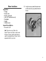
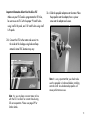
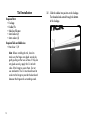
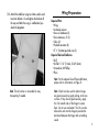
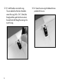
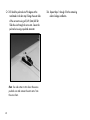
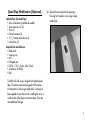
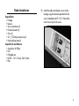
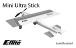
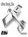
Ultra Stick 25e ® Assembly Manual Table of Contents Introduction.................................................................3 Specifications..............................................................3 Using the Manual........................................................3 Contents of Kit/Parts Layout..........................................4 Required Radio Equipment............................................5 Optional Quad Flaps...................................................5 Important Information About Motor Selection..................5 Sport Outrunner Setup..................................................5 Optional Accessories...................................................5 High Power Setup........................................................6 Warning.....................................................................6 Required Tools and Adhesives.......................................6 Note Regarding Hinges................................................7 Note on Lithium Polymer Batteries..................................7 Limited Warranty Period...............................................7 Limited Warranty & Limits of Liability..............................8 Safety Precautions........................................................9 Questions, Assistance, and Repairs................................9 Questions or Assistance................................................9 Inspection or Repairs....................................................9 Warranty Inspection and Repairs.................................10 Non-Warranty Repairs................................................10 Safety, Precautions, and Warnings..............................11 Landing Gear Installation............................................12 Motor Installation.......................................................13 Tail Installation...........................................................16 Wing Preparation......................................................17 Quad Flap Modification (Optional)..............................21 Radio Installation.......................................................25 Final Assembly..........................................................29 Control Throws..........................................................31 Center of Gravity.......................................................32 Range Testing the Radio.............................................32 Preflight....................................................................33 Flying the Ultra Stick 25e..................................... 34–35 2006 Official AMA. National Model Aircraft Safety Code..................... 36–37 Notes................................................................. 38–39 Introduction Thank you for purchasing the Ultra Stick 25e. Designed from the beginning for electric power, the Ultra Stick 25e is developed from the popular Hangar 9® Ultra Stick™ series of aircraft. You will find most all of the hard work completed for you. All flight control surfaces, control horns, wheels, and other necessary items required to speed up the building time have been installed at the factory. You will find two sets of mounting holes on the firewall to mount your choice of either the Power 25 or 32 Outrunner motors. An additional aluminum float mount is included if you wish to fly with the optional 25-size Fiberglass floats (EFLA500A). The Power 32 is recommended if you wish to fly with the floats. This is to help maintain the CG required for flight. If you wish to use the Quad Flap option you will need to use a receiver battery to power the radio as the BEC unit in most speed controls can only power 4 servos. All necessary control linkage hardware is included for the Quad Flap option if you choose to install it. Specifications Wingspan: Length: Wing Area: Weight w/o Battery: Weight w/ Battery: 50 in (127cm) 41.5 in (105cm) 480 sq in (31 sq dm) 2.6 lb (1.2 kg) 3.4 lb (1.5 kg) Using the Manual This manual is divided into sections to help make assembly easier to understand, and to provide breaks between each major section. In addition, check boxes have been placed next to each step to keep track of each step completed. Steps with a single circle () are performed once, while steps with two circles ( ) indicate that the step will require repeating, such as for a right or left wing panel, two servos, etc. Remember to take your time and follow the directions. Contents of Kit/Parts Layout Large Replacement Parts: EFL4026 Wing w/Ailerons EFL4027 Fuselage EFL4028 Tail Set EFL4029 Landing Gear w/Wheels Small Replacement Parts EFL4030 Pushrod Set EFLA213 E-flite/JR/Horizon Decals Required Radio Equipment You will need a minimum 4-channel transmitter, crystals, micro receiver, and four mini servos. You can choose to purchase a complete radio system that includes all of these items or, if you are using an existing transmitter, just purchase the other required equipment separately. You may wish to install the optional quad flaps, in which case you will need a 7-channel radio and receiver on 72MHz with mixing and six mini servos. JSP30600RS600 6-Channel Universal FM Rx w/o Crystal JRPXFR** FM Receiver Crystal JSP98110 6" Servo Extension (2) JSP20040 MN48 Mini Servo (4) JSP98020 Y-harness, standard 6" Optional Quad Flaps JRPB4041 JSP98010 JSP20040 JSP98120 Extra Rx Pack 600mAh 4.8V Square Standard Switch MN48 Mini Servo (2) 18" Servo Extension (2) Important Information About Motor Selection The Ultra Stick 25e does not include a propeller. We are recommending the Power 25 or Power 32 outrunner motors. This will provide you with excellent aerobatic power for sport pilots and a worry-free outrunner motor. Sport Outrunner Setup EFLM4025A EFLA312B THP42003S2PPL or EFLB4010 APC12060E EFLC3005 EFLAEC303 Power 25 BL Outrunner, 870Kv 40-Amp Brushless ESC (v2) 4200mAh 3S2P 11.1V Li-Po, 13GA 10-cell 1800mAh Ni-MH Electric Propeller, 12x6E Celectra 1-3 cell Li-Po Charger EC3 Dev & Batt, Male/Female This is a sport flyer setup for smooth and stable flights. Optional Accessories EFLA110 Power Meter HAN172Hangar 9 Digital Servo and Rx Current Meter High Power Setup EFLM4032A Power 32 BL Outrunner, 770Kv CSEPHX4545-Amp Brushless ESC (depending on propeller used) CSEPHX6060-Amp Brushless ESC (depending on prop used) THP42002S2PPL4200mAh 2S2P 7.4V Li-Po, 13GA (2 req in series for 14.4V) APC11070E Electric Propeller, 11x7E APC11055E Electric Propeller, 11x5.5E EFLC3005 Celectra 1 - 3 cell Li-Po Charger EFLAEC303 EC3 Dev & Batt, Male/Female This is a high power setup for very strong flight performance and float flying. Warning An RC aircraft is not a toy! If misused, it can cause serious bodily harm and damage to property. Fly only in open areas, preferably at AMA (Academy of Model Aeronautics) approved flying sites, following all instructions included with your radio. Keep loose items that can get entangled in the propeller away from the prop, including loose clothing, or other objects such as pencils and screwdrivers. Especially keep your hands away from the propeller. Required Tools and Adhesives Tools & Equipment EFLA250 Park Flyer Tool Assortment, 5-piece Or Purchase Separately EFLA257Screwdriver, #0 Phillips (or included with EFLA250) EFLA251Hex Wrench: 3/32", 7/64" (or included with EFLA250) Nut driver: 1/4" Drill Drill bit: 1/16" (1.5mm), 5/64" (2mm), Hobby knife Felt-tipped pen Pliers Note Regarding Hinges For your convenience and to speed the assembly process, the hinges have already been installed and glued. We suggest that you take a minute before beginning assembly of your model to check them. Grasp the wing and aileron at each hinge location, then gently pull on the aileron to ensure the hinges are secure and cannot easily be pulled away from either surface. Use caution when gripping the wing and aileron to avoid crushing or damaging the structure. Repeat this process for the elevator and rudder. If however, you find that the hinges pull away, simply wick thin CA into the hinge slots and reinstall the hinges/ surfaces. Note on Lithium Polymer Batteries Lithium Polymer batteries are significantly more volatile than alkaline or Ni-Cd/ Ni-MH batteries used in RC applications. All manufacturer’s instructions and warnings must be followed closely. Mishandling of Li-Po batteries can result in fire. Always follow the manufacturer’s instructions when disposing of Lithium Polymer batteries. Limited Warranty Period Horizon Hobby, Inc. guarantees this product to be free from defects in both material and workmanship at the date of purchase. Limited Warranty & Limits of Liability Pursuant to this Limited Warranty, Horizon Hobby, Inc. will, at its option, (i) repair or (ii) replace, any product determined by Horizon Hobby, Inc. to be defective. In the event of a defect, these are your exclusive remedies. This warranty does not cover cosmetic damage or damage due to acts of God, accident, misuse, abuse, negligence, commercial use, or modification of or to any part of the product. This warranty does not cover damage due to improper installation, operation, maintenance, or attempted repair by anyone other than an authorized Horizon Hobby, Inc. service center. This warranty is limited to the original purchaser and is not transferable. In no case shall Horizon Hobby’s liability exceed the original cost of the purchased product and will not cover consequential, incidental or collateral damage. Horizon Hobby, Inc. reserves the right to inspect any and all equipment involved in a warranty claim. Repair or replacement decisions are at the sole discretion of Horizon Hobby, Inc. Further, Horizon Hobby reserves the right to change or modify this warranty without notice. REPAIR OR REPLACEMENT AS PROVIDED UNDER THIS WARRANTY IS THE EXCLUSIVE REMEDY OF THE CONSUMER. HORIZON HOBBY, INC. SHALL NOT BE LIABLE FOR ANY INCIDENTAL OR CONSEQUENTIAL DAMAGES. As Horizon Hobby, Inc. has no control over use, setup, final assembly, modification or misuse, no liability shall be assumed nor accepted for any resulting damage or injury. By the act of use, setup or assembly, the user accepts all resulting liability. If you as the purchaser or user are not prepared to accept the liability associated with the use of this product, you are advised to return this product immediately in new and unused condition to the place of purchase. Safety Precautions This is a sophisticated hobby product and not a toy. It must be operated with caution and common sense and requires some basic mechanical ability. Failure to operate this product in a safe and responsible manner could result in injury or damage to the product or other property. This product is not intended for use by children without direct adult supervision. The product manual contains instructions for safety, operation and maintenance. It is essential to read and follow all the instructions and warnings in the manual, prior to assembly, setup or use, in order to operate correctly and avoid damage or injury. Questions, Assistance, and Repairs Your local hobby store and/or place of purchase cannot provide warranty support or repair. Once assembly, setup or use of the product has been started, you must contact Horizon Hobby, Inc. directly. This will enable Horizon to better answer your questions and service you in the event that you may need any assistance. Questions or Assistance For questions or assistance, please direct your email to [email protected], or call 877.504.0233 toll-free to speak to a service technician. Inspection or Repairs If your product needs to be inspected or repaired, please call for a Return Merchandise Authorization (RMA). Pack the product securely using a shipping carton. Please note that original boxes may be included, but are not designed to withstand the rigors of shipping without additional protection. Ship via a carrier that provides tracking and insurance for lost or damaged parcels, as Horizon Hobby, Inc. is not responsible for merchandise until it arrives and is accepted at our facility. Include your complete name, address, phone number where you can be reached during business days, RMA number, and a brief summary of the problem. Be sure your name, address, and RMA number are clearly written on the shipping carton. Warranty Inspection and Repairs To receive warranty service, you must include your original sales receipt verifying the proof-of-purchase date. Providing warranty conditions have been met, your product will be repaired or replaced free of charge. Repair or replacement decisions are at the sole discretion of Horizon Hobby. Non-Warranty Repairs Should your repair not be covered by warranty and the expense exceeds 50% of the retail purchase cost, you will be provided with an estimate advising you of your options. You will be billed for any return freight for non-warranty repairs. Please advise us of your preferred method of payment. Horizon Hobby accepts money orders and cashiers checks, as well as Visa, MasterCard, American Express, and Discover cards. If you choose to pay by credit card, please include your credit card number and expiration date. Any repair left unpaid or unclaimed after 90 days will be considered abandoned and will be disposed of accordingly. 10 Electronics and engines requiring inspection or repair should be shipped to the following address (freight prepaid): Horizon Service Center 4105 Fieldstone Road Champaign, Illinois 61822 All other products requiring inspection or repair should be shipped to the following address (freight prepaid): Horizon Product Support 4105 Fieldstone Road Champaign, Illinois 61822 Safety, Precautions, and Warnings As the user of this product, you are solely responsible for operating it in a manner that does not endanger yourself and others or result in damage to the product or the property of others. Carefully follow the directions and warnings for this and any optional support equipment (chargers, rechargeable battery packs, etc.) that you use. This model is controlled by a radio signal that is subject to interference from many sources outside your control. This interference can cause momentary loss of control so it is necessary to always keep a safe distance in all directions around your model, as this margin will help to avoid collisions or injury. •A lways operate your model in an open area away from cars, traffic, or people. •A void operating your model in the street where injury or damage can occur. •N ever operate the model out into the street or populated areas for any reason. • Never operate your model with low transmitter batteries. •C arefully follow the directions and warnings for this and any optional support equipment (chargers, rechargeable battery packs, etc.) that you use. •K eep all chemicals, small parts and anything electrical out of the reach of children. •M oisture causes damage to electronics. Avoid water exposure to all equipment not specifically designed and protected for this purpose. 11 Landing Gear Installation Required Parts • Fuselage • Landing gear assembly with wheels • 4-40 x 1/2" socket head screw (3) 1. Locate the landing gear assembly. Attach the landing gear assembly to the fuselage using three 4-40 x 1/2" socket head screws. Required Tools • Hex wrench: 3/32" ote: The landing gear will only fit one N direction for the holes to line up properly. 12 Motor Installation Required Parts • Fuselage • Brushless motor • Brushless speed control • 4-40 x 3/8" socket head screw (4) • Prop adapter • Propeller • 4-40 blind nut (4) 1. It may be necessary to attach the motor mount or other accessories to your particular motor at this time. Required Tools and Adhesives • Hex wrench: 3/32" Note: There are two sets of holes in the firewall. The outer set of holes is used to mount the Power 32 motor, while the inner holes are used for mounting the Power 25 motor. Use the appropriate holes for your motor. 13 2. Place the four 4-40 blind nuts on the inside of the firewall in the locations for your particular motor. Attach the Outrunner motor to the front of the firewall using four 4-40 x 3/8" socket head screws. 14 Important Information About Your Brushless ESC Make sure your ESC brake is programmed to Off. Also, be sure to use an ESC with the proper 9V cutoff when using 3-cell Li-Po packs, and 12V cutoff when using 4-cell Li-Po packs. 4. Slide the propeller adapter onto the motor. Place the propeller onto the adapter, then a spinner cone onto the adapter and secure. 3. Connect the ESC to the motor and secure it to the inside of the fuselage using hook and loop material. Actual ESC location may vary. Note: It is very important that you check to be sure the propeller is balanced before installing onto the shaft. An unbalanced propeller will cause performance issues. Note: It is wise to place a current meter in line with the ESC to check for current draw during full servo operation. Please see page 29 for further details. 15 Tail Installation Required Parts • Fuselage • Rudder/Fin • Stabilizer/Elevator • 3mm locknut (2) • 3mm washer (2) Required Tools and Adhesives • Nut driver: 1/4" Note: Before installing the tail, check to make sure the hinges are glued securely by gently pulling on the two surfaces. If they are not glued securely, apply thin CA to both sides of the hinge to secure them. Do not use accelerator. The CA must be allowed to soak into the hinge to provide the best bond between the hinge and surrounding wood. 16 1. Slide the rudder into position on the fuselage. The threaded rods extend through the bottom of the fuselage. 2. Attach the stabilizer using two 3mm washers and two 3mm locknuts. Do not tighten the locknuts all the way until after the wing is installed and you check the alignment. Wing Preparation Required Parts • Wing • 6-channel receiver • Servo w/hardware (2) • Servo extension, 6" (2) • Clevis (2) • Pushrod connector (2) • 5 5/8" (143mm) pushrod wire (2) Required Tools and Adhesives • Drill • Drill bit: 1/16" (1.5mm), 5/64" (2mm) • Screwdriver, #0 Phillips • Pliers Note: For the optional Quad Flap modification, please refer to information on Page 20. Note: The tail section is removable for easy transporting if needed. Note: Check to make sure the aileron hinges are glued securely by gently pulling on the two surfaces. If they are not glued securely, apply thin CA to both sides of the hinge to secure them. Do not use accelerator. The CA must be allowed to soak into the hinge to provide the best bond between the hinge and surrounding wood. 17 1. Install the aileron servo into the wing. The servo lead will exit the hole in the bottom center of the wing. Drill a 1/16" (1.5mm) hole through each brass eyelet into the servo mount. Be careful not to drill through the covering in the top of the wing. 18 2. Secure the servo using the hardware that was provided with the servo. 3. Attach the clevis to the 5 5/8" (143mm) pushrod wire. Thread the clevis onto the pushrod wire at least 12 turns. 4. Attach the clevis to the control horn. Plug the aileron servo into the receiver and turn on the radio. Center the aileron servo electronically. Use a felt-tipped pen to mark the pushrod wire where it crosses the servo horn. Hint: Use painter’s tape to tape the aileron to the wing tip. This will hold the aileron in the centered position while you prepare the pushrod wire. 19 5. Bend the pushrod wire 90 degrees at the mark made in the last step. Enlarge the outer hole of the servo arm using a 5/64" (2mm) drill bit. Slide the wire through the servo arm. Secure the pushrod wire using a pushrod connector. Note: Use side cutters to trim down the excess pushrod wire and remove the extra arms from the servo horn. 20 6. Repeat Steps 1 through 5 for the remaining aileron linkage installation. Quad Flap Modification (Optional) Optional Parts (for Quad Flaps) • Servo w/hardware (2 additional needed) • Servo extension, 18" (2) • Clevis (2) • Pushrod connector (2) • 5 5/8" (143mm) pushrod wire (2) • Control horn (2) 1. Remove the covering from the opening in the wing for the aileron servo using a sharp hobby knife. Required Tools and Adhesives • Hobby knife • Covering iron • Drill • Felt-tipped pen • Drill bit: 1/16" (1.5mm), 5/64" (2mm) • Screwdriver, #0 Phillips • Pliers The Ultra Stick 25e wing is designed with optional quad flaps. The ailerons have been designed with the option of cutting them in half using a hobby knife. Covering has been supplied to cover the cut ends. Installing the servos is similar to that of the aileron instructions above. There are some additional changes. 21 2. Attach an 18" servo extension to the servo. Mount the servo using the same technique described in the previous section. 22 3. Attach a clevis onto the 5 5/8" (143mm) pushrod wire. Remove the backplate from the control horn and attach the clevis to the horn. 4. Position the control horn onto the aileron. Match the fore-aft position of the horn to the one preinstalled. The pushrod wire will be parallel to the wing ribs. Mark the location for the screws using a felt-tipped pen. 5. Use a 5/32" (2mm) drill to drill the two holes for the control horn mounting screws. Use the backplate and two 2mm x 12mm screws to attach the control horn to the aileron. 23 6. Follow the procedure outline in the aileron section to mark the pushrod, bend it and attach it to the servo horn. Note: Use side cutters to trim down the excess pushrod wire and remove the extra arms from the servo horn. 24 7. Use a hobby knife or razor saw to separate the aileron from the flap. Use the covering provided with the model to seal the ends where the two were separated. Note: See our Ultra Stick 25e website page for radio tips for quad flap operation using this setup. There are also options listed if you use a 6-channel transmitter and receiver. However, this method will require the purchase of a reversed servo and the use of a Y-harness to connect your two inner location servos. Radio Installation Required Parts • Fuselage • Receiver • Servo w/hardware (2) • Pushrod connector (2) • Clevis (2) • 22 1/2" (572mm) pushrod wire (2) • Hook and loop material 1. Install the rudder and elevator servos into the fuselage using the hardware provided with the servos. Remember to drill 1/16" (1.5mm) holes into the servo tray for the screws. Required Tools and Adhesives • Screwdriver, #0 Phillips • Drill • Felt-tipped pen • Drill bit: 1/16" (1.5mm), 5/64" (2mm) • Pliers 25 2. Plug in the servos and ESC into the receiver. Mount the receiver to the side of the fuselage using hook and loop material. Route the antenna wire through the bottom of the fuselage to the rear. Note: Do not cut the antenna wire, as this will reduce the range of your radio system. 26 Important: When using high-power servos or the Quad Flap option, you will need to install a receiver battery and switch harness. 3. Thread a clevis onto the 22 1/2" (572mm) pushrod wire for the rudder. Slide the pushrod into the pushrod tube and attach the clevis to the rudder control horn. 4. With the radio on, center the servo first. Use a felt-tipped pen to mark the pushrod where it crosses the servo arm. 27 5. Bend the pushrod wire at the mark made in the previous step. Enlarge the hole in the servo arm using a 5/64" (2mm) drill bit. Secure the pushrod wire to the servo horn using a pushrod connector. Note: Use side cutters to trim down the excess pushrod wire and remove the extra arms from the servo horn. 28 6. Repeat Steps 3 through 5 for the elevator pushrod wire. Final Assembly Required Parts • Fuselage • Wing • Battery • Battery hatch • 6-32 x 1" socket head bolt (2) • #6 washer (2) • Hook and loop tape • Hook and loop strap Required Tools and Adhesives • Hex wrench: 7/64" • Hangar 9 Digital Servo & Rx Current Meter (HAN172) 1. With the aircraft fully assembled, install the battery into the battery compartment. Secure the battery using the hook and loop tape and a hook and loop strap. 2. With a servo meter we recommend you test the BEC circuitry to ensure the system can handle the current draw of the radio system. Once hooked up between the ESC and receiver, continually deflect all servos checking the current draw. You will want to verify this is within the BEC limitations. 29 Note: Place a piece of hook and loop tape on the bottom of the battery and on the fuselage where the battery rests. This will keep the battery from shifting forward or backward during extreme maneuvers. 3. Install the battery hatch to the top of the fuselage. The magnet will hold the battery hatch in place. 30 4. Plug in the aileron (and flap) servo leads. Slide the wing dowels into the holes at the front. Use the two 6-32 x 1" socket head screws and two #6 washers to secure the wing. Control Throws 1. Turn on the transmitter and receiver of your Ultra Stick 25e. Check the movement of the rudder, elevator and ailerons using the transmitter. Reverse the direction of the servos at the transmitter if necessary. Low Rate High Rate Ailerons: Up/Down 1/2" (13mm) 7/8" (22mm) Elevator: Up/Down 3/4" (19mm) 1" (25mm) 2" (51mm) 2 1/2" (63.5mm) Rudder: 2. Use a ruler to adjust the throw of the elevator, ailerons and rudder. Adjust the position of the pushrod at the control horn to achieve the following measurements when moving the sticks to their endpoints. Right/Left These are general guidelines measured from our own flight tests. You can experiment with higher rates to match your preferred style of flying. Measurements are taken at the widest point on the surface. 31 Center of Gravity Caution: Do not inadvertently skip this step! The recommended Center of Gravity (CG) location for the Ultra Stick 25e is 2 1/2" (63.5mm) behind the leading edge of the upper wing against the fuselage. After the first flights, the throws can be adjusted for your personal preference. Range Testing the Radio 1. Be sure to range check your radio before each flying session. This is accomplished by turning on your transmitter with the antenna collapsed. Turn on the receiver in your airplane. With your airplane on the ground and the motor running, you should be able to walk 30 paces (approximately 100 feet) away from your airplane and still have complete control of all functions. If not, don’t attempt to fly! Have your radio equipment checked out by the manufacturer. 2. Double-check that all controls (aileron, elevator, rudder and throttle) move in the correct direction. 3. Be sure that your transmitter batteries are fully charged, per the instructions included with your radio. 32 Preflight Check Your Radio Before going to the field, be sure that your batteries are fully charged per the instructions included with your radio. Charge both the transmitter and receiver pack for your airplane. Use the recommended charger supplied with your particular radio system, following the instructions provided with the radio. In most cases, the radio should be charged the night before going out flying. Before each flying session, be sure to range check your radio. See your radio manual for the recommended range and instructions for your radio system. Each radio manufacturer specifies different procedures for their radio systems. Next, start the motor. With the model securely anchored, check the range again. The range test should not be significantly affected. If it is, don’t attempt to fly! Have your radio equipment checked out by the manufacturer. Note: Keep loose items that can get entangled in the propeller away from the prop. These include loose clothing, or other objects such as pencils and screwdrivers. Especially keep your hands away from the propeller. Double-check that all controls (aileron, elevator, rudder and throttle) move in the correct direction. Check the radio installation and make sure all the control surfaces are moving correctly (i.e. the correct direction and with the recommended throws). Test run the motor and make sure it transitions smoothly from off to full throttle and back. Also ensure the motor is installed according to the manufacturer’s instructions, and it will operate properly. Check all the control horns, servo horns, and clevises to make sure they are secure and in good condition. Replace any items that would be considered questionable. Failure of any of these components in flight would mean the loss of your aircraft. 33 Flying the Ultra Stick 25e You will find the Ultra Stick 25e to be a solid, honest sport model. It is capable of handling windy days if you choose. Flight times with the 1800mAh Ni-MH battery will be around 9–10 minutes. When using the Thunder Power 4200 3S2P battery, flight times of close to 17 minutes are common. Ensure your CG is set according to the manual and power up the aircraft. Move your throttle trim up slowly until the motor just begins to spin. This will be your flight idle that will help to establish a longer glide path and tends to make landings easier. Taxi out to the runway and line up into the wind. You will find the rudder very effective on the Ultra Stick 25e and takeoffs are very short. Apply power smoothly and begin the takeoff roll. Correct with rudder as necessary and apply up elevator slowly until the model lifts off. Once in the air, trim the model for level flight. Once trimmed, you will find the aerobatic capabilities are very good and the Ultra Stick 25e can perform any maneuver asked. 34 Landing the Ultra Stick 25e is as easy as setting up on final approach, lowering the throttle to idle and gliding in to a soft three point touch-down. Go-around’s are accomplished with full throttle and a gentle pull up. Flying with the optional floats adds another level of fun to the Ultra Stick 25e. Mount your floats up and ensure the water rudder is traveling in the correct direction. Rebalance the model to ensure the CG is correct. Lead weights have been preinstalled in the floats at the factory to help maintain the correct CG. If your model feels tail heavy with the floats installed, please use a small amount of stick on weight on the bottom front area of the floats to adjust the CG as necessary. Once at the lake, power the model up and set it in the water. Next adjust the throttle trim until the motor begins to spin. Taxi out into the wind. Do this by holding full up elevator during the taxi to reduce the amount of water splash created by the front of the floats and prop blast. Steer the model with rudder during taxiing. Flying the Ultra Stick 25e Once lined up for takeoff, apply full up elevator and apply full power in a smooth fashion. As the model accelerates and the floats come up on step, relax the elevator slowly. You will find as you relax the elevator through half travel the model should break water and begin a gentle climb out. Re-trim the model for level flight with the floats installed. You will notice the model will require more down elevator during inverted flight, and the rolls will not be quite as axial as they were when flying from land. The floats cause a pendulum effect on the aircraft during flight, which is common with all models outfitted with floats. Keep in mind the model is heavier when outfitted with floats and has a larger drag coefficient which will require more power to stay in the air. Landing with floats is as easy as landing on a runway. Setup on the downwind leg and reduce power to 1/4 throttle. As you turn base and then to final, continue this turn in a shallow descent keeping the model’s nose pointed down. Reduce throttle to idle as you line up on final approach and maintain a shallow descent towards the water. As you come to an altitude of approximately 15 feet, begin to level off. If the model slows too much, you may need to apply a small amount of power. As the model comes closer to the water, begin to feed up elevator in slowly and smoothly, trying to keep the plane from ballooning, but keeping the nose at a positive angle to the water. You will find yourself touching down on the water with half elevator applied. Once down on the water, hold full up elevator as the model slows. Use full up elevator during taxi back to shore. Flight times are reduced by about 25% when flying from the water. We hope you enjoy the Ultra Stick 25e as much as we do, both on land and water. Happy landings. 35 2006 Official AMA National Model Aircraft Safety Code GENERAL 1) I will not fly my model aircraft in sanctioned events, air shows or model flying demonstrations until it has been proven to be airworthy by having been previously, successfully flight tested. 2) I will not fly my model higher than approximately 400 feet within 3 miles of an airport without notifying the airport operator. I will give right-of-way and avoid flying in the proximity of full-scale aircraft. Where necessary, an observer shall be utilized to supervise flying to avoid having models fly in the proximity of full-scale aircraft. 3) Where established, I will abide by the safety rules for the flying site I use, and I will not willfully or deliberately fly my models in a careless, reckless and/or dangerous manner. 4) The maximum takeoff weight of a model is 55 pounds, except models flown under Experimental Aircraft rules. 36 5) I will not fly my model unless it is identified with my name and address or AMA number on or in the model. (This does not apply to models while being flown indoors.) 6) I will not operate models with metal-bladed propellers or with gaseous boosts, in which gases other than air enter their internal combustion engine(s); nor will I operate models with extremely hazardous fuels such as those containing tetranitromethane or hydrazine. RADIO CONTROL 1) I will have completed a successful radio equipment ground range check before the first flight of a new or repaired model. 2) I will not fly my model aircraft in the presence of spectators until I become a qualified flier, unless assisted by an experienced helper. 3) At all flying sites a straight or curved line(s) must be established in front of which all flying takes place with the other side for spectators. Only personnel involved with flying the aircraft are allowed at or in front of the flight line. Intentional flying behind the flight line is prohibited. 2006 Official AMA National Model Aircraft Safety Code 4) I will operate my model using only radio control frequencies currently allowed by the Federal Communications Commission. (Only properly licensed Amateurs are authorized to operate equipment on Amateur Band frequencies.) 5) Flying sites separated by three miles or more are considered safe from site-to-site interference, even when both sites use the same frequencies. Any circumstances under three miles separation require a frequency management arrangement, which may be either an allocation of specific frequencies for each site or testing to determine that freedom from interference exists. Allocation plans or interference test reports shall be signed by the parties involved and provided to AMA Headquarters. Documents of agreement and reports may exist between (1) two or more AMA Chartered Clubs, (2) AMA clubs and individual AMA members not associated with AMA Clubs, or (3) two or more individual AMA members. 6) For Combat, distance between combat engagement line and spectator line will be 500 feet per cubic inch of engine displacement. (Example: .40 engine = 200 feet.); electric motors will be based on equivalent combustion engine size. Additional safety requirements will be per the RC Combat section of the current Competition Regulations. 7) At air shows or model flying demonstrations, a single straight line must be established, one side of which is for flying, with the other side for spectators. 8) With the exception of events flown under AMA Competition rules, after launch, except for pilots or helpers being used, no powered model may be flown closer than 25 feet to any person. 9) Under no circumstances may a pilot or other person touch a powered model in flight. 37 Notes 38 Notes 39 ® © 2006 Horizon Hobby, Inc. 4105 Fieldstone Road Champaign, Illinois 61822 (877) 504-0233 horizonhobby.com E-fliteRC.com 8921