1
Orion LT Weather Station
1
________________________________________________________________________________________________________________________
Orion LT Wind Monitor™
User Manual
Version 1.08
Serial Number: _____________________________
Date Purchased: ___________________________
All specifications subject to change without notice.
Printed in U. S. A.
Columbia Weather Systems, Inc.
2
Orion LT Weather Station
________________________________________________________________________________________________________________________
© Copyright 2005 - 2010 Columbia Weather Systems, Inc. All Rights Reserved.
Proprietary Notice: Orion, Orion LT, Orion LX, Capricorn 2000, Capricorn 2000MP and Capricorn 2000EX
are trademarks of Columbia Weather Systems, Inc. The information and drawings contained herein are
the sole property of Columbia Weather Systems, Inc. Use of this publication is reserved exclusively for
customers of Columbia Weather Systems, Inc. and their personnel. Reproduction of this material is
forbidden without the express written consent of Columbia Weather Systems, Inc.
Parts of the Orion LT Weather Station™ user manual were adapted from the Weather Transmitter
WMT52 User’s Guide with permission from Vaisala Oyj.
WINDCAP®, RAINCAP®, HUMICAP®, BAROCAP® and THERMOCAP® are registered trademarks of
Vaisala.
Orion LT Weather Station
3
________________________________________________________________________________________________________________________
Welcome!
Welcome to the Columbia Weather Systems family of users and congratulations on your purchase of the
Orion LT Wind Monitor.
Please read this manual completely prior to installation.
Columbia Weather Systems, Inc.
4
Orion LT Weather Station
________________________________________________________________________________________________________________________
Important Notice: Shipping Damage
BEFORE YOU READ ANY FURTHER, please inspect all system components for obvious shipping
damage. The Orion LT is a high precision instrument and can be damaged by rough handling. Your unit
was packaged to minimize the possibility of damage in transit. Therefore, we recommend that you save
the shipping container for any future shipment of your Orion LT unit.
In the event your order arrives in damaged condition, it is important that the following steps be taken
immediately. The title transfers automatically to you, the customer, once the material is entrusted to the
transport company.
NOTE: DO NOT RETURN THE INSTRUMENT TO COLUMBIA WEATHER SYSTEMS until the following
steps are completed. Failure to follow this request will jeopardize your claim.
1. Open the container and inspect the contents. Do not throw away the container or any damaged
parts. Try to keep items in the same condition as originally received.
2. Notify the transport company immediately in writing, preferably by facsimile, about the shipping
damage.
3. Wait for the transport company’s representative to inspect the shipment personally.
4. After inspection, request permission from Columbia Weather Systems for return of the damaged
instrument by calling the Service Department, (503) 629-0887.
5. Return approved items to us at the following address:
Columbia Weather Systems, Inc.
2240 NE Griffin Oaks Street, Suite 100
Hillsboro, OR 97124
6. After return authorization is issued and we receive the instrument, an estimate of the cost of
repair will be sent to you for submittal to the transport company as a claim.
Orion LT Weather Station
5
________________________________________________________________________________________________________________________
ESD Protection
Electrostatic Discharge (ESD) can cause immediate or latent damage to electronic circuits. Vaisala
products are adequately protected against ESD for their intended use. However, it is possible to damage
the product by delivering electrostatic discharges when touching, removing, or inserting any objects inside
the equipment housing.
To make sure you are not delivering high static voltages yourself:
1. Handle ESD sensitive components on a properly grounded and protected ESD workbench. When
this is not possible, ground yourself with a wrist strap and a resistive connection cord to the
equipment chassis before touching the boards. When neither of the above is possible, at least
touch a conductive part of the equipment chassis with your other hand before touching the
boards.
2. Always hold the boards by the edges and avoid touching the component contacts.
Columbia Weather Systems, Inc.
6
Orion LT Weather Station
________________________________________________________________________________________________________________________
Table of Contents
WELCOME! ..................................................................................................................................3
IMPORTANT NOTICE: SHIPPING DAMAGE .......................................................................4
ESD PROTECTION.......................................................................................................................................................5
SECTION 1: INTRODUCTION ..................................................................................................9
THE ORION LT WIND MONITOR .................................................................................................................................9
SPECIFICATIONS .........................................................................................................................................................9
Operating Conditions ............................................................................................................................................9
Wind Speed ............................................................................................................................................................9
Wind Direction ......................................................................................................................................................9
Input Voltage .........................................................................................................................................................9
Heating Power Source.........................................................................................................................................10
Sensor Housing....................................................................................................................................................10
PRINCIPLES OF MEASUREMENTS ..............................................................................................................................11
Wind Measurement ..............................................................................................................................................11
SECTION 2: PHYSICAL DESCRIPTION...............................................................................13
ORION LT SENSOR TRANSMITTER ............................................................................................................................13
Sensor Transmitter Components..........................................................................................................................13
Bottom of the Transmitter....................................................................................................................................14
Mounting Adapter................................................................................................................................................14
Heating (Optional) ..............................................................................................................................................14
Orion Interface Module .......................................................................................................................................15
SURGE/LIGHTNING PROTECTORS..............................................................................................................................16
WEATHERMASTER SOFTWARE (OPTIONAL) .........................................................................................................17
WEATHER DISPLAY CONSOLE (OPTIONAL) ..............................................................................................................18
WEATHER MICROSERVER ........................................................................................................................................19
SECTION 3: INSTALLATION .................................................................................................21
WEATHER STATION SYSTEM CONFIGURATION .........................................................................................................21
INSTALLATION OVERVIEW .......................................................................................................................................22
UNPACKING THE UNIT ..............................................................................................................................................22
INSTALLING THE ORION LT SENSOR TRANSMITTER .................................................................................................23
Site Selection: ......................................................................................................................................................23
Installing the Mounting Adapter..........................................................................................................................23
North Alignment ..................................................................................................................................................23
Installing the Mast ...............................................................................................................................................24
Location...............................................................................................................................................................24
Mounting Method ................................................................................................................................................24
Routing Cable......................................................................................................................................................25
CONNECTING THE SENSOR TRANSMITTER TO THE INTERFACE MODULE ..................................................................26
SECTION 4: OPTIONAL SENSOR MOUNTING HARDWARE.........................................27
Roof Mounting .....................................................................................................................................................27
Wall Mounting .....................................................................................................................................................29
Tripod ..................................................................................................................................................................31
Specifications.......................................................................................................................................................31
ORION LT SENSOR DATA OUTPUT DEFINITION ........................................................................................................33
Wind data.............................................................................................................................................................33
Supervisory Data:................................................................................................................................................33
CRC-16 Computation ..........................................................................................................................................34
Encoding the CRC as ASCII Characters .............................................................................................................34
SECTION 5: CALIBRATION....................................................................................................35
FACTORY CALIBRATION ...........................................................................................................................................35
Orion LT Weather Station
7
________________________________________________________________________________________________________________________
SECTION 6: MAINTENANCE .................................................................................................37
CLEANING ................................................................................................................................................................37
FACTORY CALIBRATION AND REPAIR SERVICE ........................................................................................................37
SECTION 7: TROUBLESHOOTING.......................................................................................39
SECTION 8: USER SUPPORT INFORMATION ...................................................................41
LIMITED WARRANTY ...............................................................................................................................................41
EXCLUSIONS......................................................................................................................................................41
RETURN FOR REPAIR PROCEDURE ............................................................................................................................41
UNIT CONVERSION ...................................................................................................................................................42
Speed....................................................................................................................................................................42
Columbia Weather Systems, Inc.
8
Orion LT Weather Station
________________________________________________________________________________________________________________________
Orion LT Weather Station
9
________________________________________________________________________________________________________________________
SECTION 1: INTRODUCTION
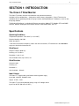
The Orion LT Wind Monitor
The Orion LT provides ultrasonic wind direction and speed measurements.
Available in three configurations – fixed-mount, vehicle-mount, and portable – Orion LT data can be
monitored with our proprietary Weather Display Console and WeatherMaster™ Software, as well as with
third-party software.
The Weather MicroServer is available for Ethernet connectivity, Modbus/TCP, Modbus RTU and SNMP
interface, Weather Underground and CWOP interface, XML weather data, and FTP.
Specifications
Operating Conditions
Temperature Operation: -52 to +60°C (-6- to +140°F)
Relative Humidity: 0 to 100%
Wind*: 0 to 60 m/s
* Due to the measurement frequency used in the sonic transducers, RF interference in the 200-400kHz
range can disturb wind measurement.
Wind Speed
Range: 0-135mph (0-60 m/s)
Accuracy: ±3% at 10 m/s
Resolution: 1 mph (1 m/s)
Units Available: knots, mph, km/hr, m/s
Wind Direction
Azimuth: 0-360°
Accuracy: ±3°
Resolution: 1°
Units Available: ° Azimuth
Input Voltage
The Orion LT is supplied with a wall mount switching power supply
Input: 100 - 240 VAC, 50/60 HZ, 0.6A
Output: 12 VDC, 1.25A
The Orion LT can also be powered directly using a DC voltage source
Input: 5 to 30 VDC (60 mA at 12 VDC)
Columbia Weather Systems, Inc.
10
Orion LT Weather Station
________________________________________________________________________________________________________________________
Heating Power Source
Input: 5 to 30 VDC (1.1 A at 12 VDC)
Sensor Housing
Protection class: IP66 (with mounting adapter)
Materials: Polycarbonate + 20% glass fiber, stainless steel (AISI 316)
Weight: 595 g (1.3 lbs)
Orion LT Weather Station
11
________________________________________________________________________________________________________________________
Principles of Measurements
Wind Measurement
Both wind speed and direction are measured using advanced ultrasonic technology. The sensor utilizes
ultrasound to determine horizontal wind readings. The array of three equally-spaced ultrasonic
transducers on a horizontal plane is an ideal design that ensures accurate wind measurement from all
directions, without blind angles or corrupted readings.
The wind sensor has no moving parts, which makes it virtually maintenance free.
Wind speed and wind directions are determined by measuring the time it takes the ultrasound to travel
from each transducer to the other two.
The wind sensor measures the transit time (in both directions) along the three paths established by the
array of transducers. This transit time depends on the wind speed along the ultrasonic path. For zero
wind speed, both the forward and reverse transit times are the same. With wind along the sound path, the
up-wind direction transit time increases and the down-wind transit time decreases.
The wind speed is calculated from the measured transit times using the following formula:
Vw = 0.5 x L x (1/ tf – 1/tr
where:
Vw = Wind speed
L = Distance between the two transducers
tf = Transit time in forward direction
tr = Transit time in reverse direction
Measuring the six transit times allows Vw to be computed for each of the three ultrasonic paths. The
computed wind speeds are independent of altitude, temperature and humidity, which are cancelled out
when the transit times are measured in both directions, although the individual transit times depend on
these parameters.
Using Vw values of two array paths is enough to compute wind speed and wind direction. A signal
processing technique is used so that wind speed and wind direction are calculated from the two array
paths of best quality.
The wind speed is represented as a scalar speed in selected units (m/s, kt, mph, km/h). The wind
direction is expressed in degrees (°). The wind direction reported indicates the direction that the wind
comes from. North is represented as 0°, east as 90°, south as 180°, and west as 270°.
The wind direction is not calculated when the wind speed drops below 0.05 m/s. In this case, the last
calculated direction output remains until the wind speed increases again to the level of 0.05 m/s.
The average values of wind speed and direction are calculated as a scalar average of all samples over
the selected averaging time (1 ... 900 s). The sample count is based on a 4 Hz sampling rate. The
minimum and maximum values of wind speed and direction represent the corresponding extremes during
the averaging time.
Columbia Weather Systems, Inc.
12
Orion LT Weather Station
________________________________________________________________________________________________________________________
Orion LT Weather Station
13
________________________________________________________________________________________________________________________
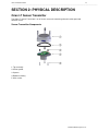
SECTION 2: PHYSICAL DESCRIPTION
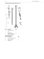
Orion LT Sensor Transmitter
The Orion LT Sensor Transmitter is an all-in-one sensor unit containing ultrasonic wind speed and
direction sensor.
Sensor Transmitter Components
1: Top assembly
2: Silicon gasket
3: Spacers
4: Bottom assembly
5. Allen screws
Columbia Weather Systems, Inc.
14
Orion LT Weather Station
________________________________________________________________________________________________________________________
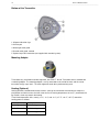
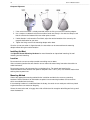
Bottom of the Transmitter
1: Alignment direction sign
2: Service port
3: Water tight cable gland
4: Unused cable gland, covered
5. Optional 8-pin M12 connector (not supplied with standard system).
Mounting Adapter
To facilitate easy installation and north alignment, the Orion LT Sensor Transmitter comes standard with
a mounting adapter. The mounting adapter is easily connected on the end of the mast and the sensor
transmitter simply snaps into it. The north alignment needs to be performed only once.
Heating (Optional)
Heating elements located below the top stainless steel cap and inside the wind transducers keeps the
precipitation and wind sensors free from snow and ice. A heating temperature sensor (Th) underneath the
top stainless steel cap controls the heating.
Three fixed temperature limits, namely +3 °C, -2 °C, and -4 °C (+37 °F, +38 °F, +25 °F) control the
heating power as follows:
Th > +3 °C
heating is off
-2 °C < Th < +3 °C
50% heating power
-4 °C < Th < -2 °C
100% heating power
Th < -4 °C
50% heating power
Orion LT Weather Station
15
________________________________________________________________________________________________________________________
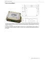
Orion Interface Module
The Orion Interface Module is used to supply power to the sensor transmitter and to provide two RS-232
communication ports. The RS-232 ports can be connected to computers, display consoles, transceivers,
and other such devices.
The Interface Module has two LED indicators. The green LED is a power indicator and the red LED is a
data indicator. In normal operation, the red LED will flash every second to indicate a data record being
transmitted.
Columbia Weather Systems, Inc.
16
Orion LT Weather Station
________________________________________________________________________________________________________________________
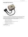
Surge/Lightning Protectors
A nearby lightning strike may induce a high voltage surge which the internal suppressor of your weather
instrument may not be able to withstand, causing significant damage to the weather station. Protect your
weather station investment with the Orion Surge Protector. This compact transient overvoltage
suppressor is designed for weather stations in areas with an elevated risk of lightning strike such as on
top of high buildings, or anywhere with cable lengths greater than 100 feet.
•
Superior 3-stage surge protection
•
Tolerates up to 10kA surge currents
•
Both differential and common mode protection on each channel
•
Filtering against HF and RF noise
•
Two power channels and two data channels
•
Environmental protection class IP66
Catalog Number: 8355
Includes adjustable mounting kit
Orion LT Weather Station
17
________________________________________________________________________________________________________________________
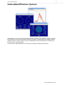
WeatherMaster
Software (Optional)
WeatherMaster is a professional grade weather monitoring software. This software package is designed
for specialized markets that require robust weather calculations, interoperability with computer models,
and data interfaces to other industrial systems. WeatherMaster utilizes Microsoft Access database for
easy data access and manipulation.
Please refer to the WeatherMaster user manual for installation and operation procedures
Columbia Weather Systems, Inc.
18
Orion LT Weather Station
________________________________________________________________________________________________________________________
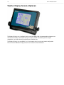
Weather Display Console (Optional)
The Weather Display uses “intelligent” touch-screen technology. With its programmable microprocessor
and abundant memory, the Weather Display can display weather information, perform complex
computations, and store relatively large amounts of weather data.
The Weather Display is also available in a 19” rack-mount chassis and a panel-mount configuration.
Please refer to the Weather Display Console user manual for more information.
Orion LT Weather Station
19
________________________________________________________________________________________________________________________
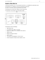
Weather MicroServer
The Weather MicroServer uses a small computer board that runs an imbedded Linux operating system.
The MicroServer has 512MB flash memory for data logging and operation.
The Orion LT transmitter connects to the MicroServer via COM1.
The MicroServer has two RS-232 COM ports and an Ethernet port
A second Orion LT transmitter can be connected to COM2.
The MicroServer offers the following:
•
XML Weather Data
•
FTP weather data in XML or CSV format
•
Modbus/TCP, Modbus RTU, and Modbus ASCI interfaces
•
SNMP interface
•
Weather Underground interface
•
CWOP interface
•
Three months of data logging at 1-minute interval
•
Interface to optional visibility and solar radiation sensors
Columbia Weather Systems, Inc.
20
Orion LT Weather Station
________________________________________________________________________________________________________________________
Orion LT Weather Station
21
________________________________________________________________________________________________________________________
SECTION 3: INSTALLATION
Weather Station System Configuration
The Orion LT Weather Station can be installed in multiple configurations depending on the
communication options, power availability and viewing options.
Columbia Weather Systems, Inc.
22
Orion LT Weather Station
________________________________________________________________________________________________________________________
Installation Overview
Unpacking the Unit
Installing Sensor Transmitter
Installing the Interface Module
Connecting the Sensor Transmitter to the Interface Module
Connecting to Weather Display, Computer, and/or MicroServer
Unpacking the Unit
The sensor transmitter comes in a custom shipping container. Be careful when removing the device.
CAUTION: Beware of damaging any of the wind transducers located at the top of the three antennas.
Dropping the device can break or damage the transducers. If the antenna bends or twists, the re-aligning
can be difficult or impossible.
Unpack the Orion LT weather station and verify that all parts are included.
1. Standard system includes:
Orion LT Sensor Transmitter
50 ft sensor cable + additional cable length if ordered
Orion Interface Module
(2) 3-position terminal blocks
Interface module power supply
User Manual
6-foot RS-232 cable + additional cable length if ordered
2. Weather Display Console (Optional)
Display Console
Power supply
6-foot RS-232 cable + additional cable length if ordered
User manual
3. WeatherMaster 2000 software and user manual (optional)
4. Weather MicroServer (optional)
MicroServer
Power supply
Ethernet cable
User manual
Inspect all system components for obvious shipping damage (Refer to “Important Notice: Shipping
Damage” in case of damage).
Save the shipping carton and packing material in case the unit needs to be returned to the factory. If the
system does not operate or calibrate properly, see Section 6: Maintenance and Section 7:
Troubleshooting, for further instructions.
Orion LT Weather Station
23
________________________________________________________________________________________________________________________
Installing the Orion LT Sensor Transmitter
Site Selection:
Finding a suitable site for the sensor transmitter is important for getting representative ambient
measurements. The site should represent the general area of interest.
The sensor transmitter should be installed in a location that is free from turbulence caused by nearby
objects, such as trees or buildings.
WARNING: To protect personnel (and the device), a lightning rod should be installed with the tip at least
40 inches (one meter) above the sensor transmitter. The rod must be properly grounded, compliant with
all local applicable safety regulations.
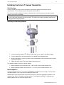
Installing the Mounting Adapter
1. Insert the mounting adapter in the transmitter lower side as shown in the diagram above.
2. Turn the adapter firmly until you feel that it has snapped into the locked position.
3. Align the transmitter in such a way that the arrow (at the bottom of the transmitter) points to north
(see North Alignment).
4. Tighten the fixing screw to fix the adapter firmly to the mast.
The mounting adapter installs on a mast as follows:
1. Mounting adapter with sleeve mounts on a 1.05 inch (26.7 mm) outside diameter mast.
2. Mounting adapter without sleeve mounts on a 1.18 inch (30 mm) outside diameter mast.
North Alignment
To help the alignment, there is an arrow and text North on the bottom of the transmitter. The transmitter
should be aligned in such a way that this arrow points to the north.
Wind direction can be referred either the true north, which uses the earth’s geographic meridians, or to
magnetic north, which is read with a magnetic compass. The magnetic declination is the difference in
degrees between the true north and magnetic north.
Columbia Weather Systems, Inc.
24
Orion LT Weather Station
________________________________________________________________________________________________________________________
Compass Alignment
1. If the sensor transmitter is already mounted, loosen the fixing screw on the mounting adapter.
2. Use a compass to determine that the transducer heads are exactly in line with the compass and
that the arrow on the bottom of the transmitter points to north.
3. If wind direction is referenced to True North, adjust the north orientation of the sensor by the
magnetic declination for your area.
4. Tighten the fixing screw on the mounting adapter when done.
Once the sensor transmitter is aligned to north, the transmitter can be removed from the mounting
adapter without losing the north orientation.
Installing the Mast
See Optional Sensor Mounting Hardware for more information on sloped roof mounting, flat roof
mounting and wall mounting
Location
Do not attach the sensor transmitter to radio transmitting mast or tower.
Select a mounting location that will allow the sensor cable to be routed away from other data cables to
avoid interference.
Do not mount sensors close to power lines or telephone lines. For normal roof mounting, the
recommended minimum distance from power or telephone lines is 25 ft. (8 m). Use extreme caution when
working close to power lines.
Mounting Method
Choose the appropriate mounting method for the installation and obtain the necessary mounting
hardware. Refer to Section 4 for information on optional sensor mounting hardware and accessories
which are available from the factory.
If the mounting hardware is not obtained from the factory, be certain to use metal parts which are plated
or galvanized to assure maximum longevity.
Secure the mast to the roof, using guy wires with sufficient tensile strength or to building wall using a wallmount hardware kit.
Orion LT Weather Station
25
________________________________________________________________________________________________________________________
Routing Cable
Use plastic tie wraps secure the cable to mast. Be sure that one is used at the mast base. Tighten the tie
wraps securely and clip off any excess length with a wire cutter tool.
Route the cable back to the Interface Module.
Any mast or tower should always be properly earth grounded to minimize electrical storm damage. The
use of a properly grounded metal mast or tower, however, does not insure protection from electrostatic
discharge. These items could become electrically charged resulting in damage to the sensors and/or
console. This could damage the system in the event of an electrical storm. Use insulated standoffs (user
supplied, see Section 4) when routing cable to help avoid this problem.
CAUTION: There may be electric wires in the wall. We recommend that you shut off the electricity in the
room(s) where you are drilling.
Note: If the standard 50 ft. cable provided with the sensor transmitter is not long enough, it may be
extended by splicing on an appropriate length of 22-gauge, stranded, seven conductor shielded cable
with the same color code. When cutting and splicing, insure good contacts, proper color coding of the
terminal leads, and a good seal. (A good solder splice, and water proof insulation are essential; merely
twisting the respective wires together is not adequate.) Additional cable (Catalog No. 81542) and a water
tight splice kit (Cat. No. 81580) are available from the factory.
Once the sensor transmitter has been placed, route the cable back to the Interface Module.
Columbia Weather Systems, Inc.
26
Orion LT Weather Station
________________________________________________________________________________________________________________________
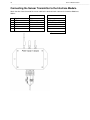
Connecting the Sensor Transmitter to the Interface Module
Attach the wires from the end of the sensor cable to the terminal block screws on the Interface Module as
follows:
1
2
3
4
5
6
Signal
+12 V
GND
N/C
GND
RX
TX
Standard
Color
RED
White and Bare
No connection
Green
Black
Orange
Heated
Color
RED and Brown
White, Blue, and Bare
No connection
Green
Black
Orange
Orion LT Weather Station
27
________________________________________________________________________________________________________________________
Section 4: Optional Sensor Mounting
Hardware
Fiberglass and steel 10-foot masts are available for use with either Roof Mounting Hardware Kit (Cat. No.
88002). Only the steel 10-foot mast is available for use with the Wall Mounting Kit (Cat. No. 88003).
A 10-foot free standing tripod is also available.
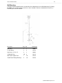
Roof Mounting
The Roof Mounting Kit (Cat. No. 88002) is suitable for both a slanted and flat roof installation. The figure
and table below illustrates and describes the individual parts. Items included in the kit are marked with an
asterisk (*). Individual parts are also available.
Description
Pkg. Ref
Catalog No.
Mast, 10 ft. (steel or fiberglass)
1
1
88005 / 88004
*Universal Mast Mount
1
2
88010
Lag Screw, Roof Mast Mount
3
3
88020
4
3
88030
*Guy Ring and Collar
1
4
88040
*Cable Standoffs, Wood Screw
4
5
88050
Cable Standoffs, Nail-In
(for masonry application)
2
5
88060
1/4" x 4" (for shake roofs
*Lag Screw, Roof Mast Mount
1/4" x 2 1/4" (for comp. roofs)
Columbia Weather Systems, Inc.
28
Orion LT Weather Station
________________________________________________________________________________________________________________________
Guy Wire Clamps, 1/8"
3
(not shown)
88070
*Steel Guy Wire, Galvanized
50 ft. 6
88080
*Eye Bolt Wood Screws, 1/4" x 3"
4
7
88090
Turnbuckles, 6" open x 4" closed
2
(not shown)
88100
*Cable Nail Clips
20
8
88110
Wall Feed Through Tube
1
10
88130
*Cable Feed Through Bushings
4
10
88140
Orion LT Weather Station
29
________________________________________________________________________________________________________________________
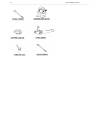
Wall Mounting
The figure and table below illustrates and describes the individual parts in the Wall Mounting Kit (Catalog
No. 88003). Only available with the steel mast. Items included in the kit are marked with an asterisk (*).
Individual parts are also available.
Description
Pkg. Ref
Catalog No.
Mast, 10 ft.
1
1
88005
*4" Wall Mount
2
9
88120
Lag Screw, 1/4" x 2 1/4"
4
3
88030
*Cable Nail Clips
20
8
88110
Wall Feed Through Tube
1
10
88130
*Cable Feed Through Bushings
4
10
88140
Columbia Weather Systems, Inc.
30
Orion LT Weather Station
________________________________________________________________________________________________________________________
Orion LT Weather Station
31
________________________________________________________________________________________________________________________
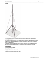
Tripod
The instrumentation tripod is designed to provide up to 10 feet of stable, secure support for your
meteorological sensors.
Constructed from welded aluminum and is powder coated for appearance and longevity, the 15-pound
tripod can easily support up to 60 pounds of equipment. An optional tie-down kit allows for additional
security in high-wind areas.
Insert the legs into the main body and install the stainless steel retainer pins. Extend the mast to the
desired height and insert another retainer pin. Install the guy wires to complete the installation.
Specifications
Capacity: Supports up to 60 lbs.
Shipping Weight: 17 lbs
Shipping Box Dimensions: 70" x 8" x 8"
Tripod and Tie Down Kit Catalog Number: 88019
Columbia Weather Systems, Inc.
32
Orion LT Weather Station
________________________________________________________________________________________________________________________
Tripod 10-foot (Catalog No. 88019) Parts List:
Item #
Description
Qty
1
Body/Mast Assembly
1
2
Legs
3
3
4
Retainer Pins
4
Guy Wire Ring with
1
3 Wires and Turnbuckles
Tiedown Kit Parts List:
Item # Description
Qty
5
Anchor Screw with Chain
1
6
Clamp with Strap
1
7
Retainer Pin
1
Orion LT Weather Station
33
________________________________________________________________________________________________________________________
Orion LT Sensor Data Output Definition
Wind data is transmitted every second. A Supervisory message is transmitted every 60 seconds when
heating is turned off and every 15 seconds when heating is turned on.
The RS-232 interface is as follows:
Bits per Second (baud rate): 9600
Data bits: 8
Parity: None
Stop bits: 1
Flow control: None
Note: The # sign after a parameter value indicates an invalid value.
Wind data
Example:
0r1,Dn=240D,Dm=249D,Dx=260D,Sn=4.3S,Sm=4.9S,Sx=5.4SMCO
where
0r1 = Wind message
Dn = Wind direction minimum (D = degrees)
Dm = Wind direction average (D = degrees)
Dx = Wind direction maximum (D = degrees)
Sn = Wind speed minimum (S = mph)
Sm = Wind speed average (S = mph)
Sx = Wind speed maximum (S = mph)
MCO = CRC-16 code
Supervisory Data:
Example:
0r5,Th=69.0F,Vh=0.0N,Vs=17.0V,Vr=3.483VCa~
where
0r5= Supervisory message
Th = Heating temperature (F = °F)
Vh = Heating voltage (N = heating is off)
Vs = Supply voltage (V = V)
Vr= 3.5 V reference voltage (V = V)
Ca~ = CRS-16 code
Columbia Weather Systems, Inc.
34
Orion LT Weather Station
________________________________________________________________________________________________________________________
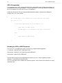
CRC-16 Computation
The computation of the CRC is performed on the data response before parity is added. All operations are
assumed to be on 16 bit unsigned integers. The least significant bit is on the right. Numbers preceded by
0x are in hexadecimal. All shifts shift in a zero. The algorithm is:
Initialize the CRC to zero. For each character beginning with the address, up to but not including the
carriage return (<cr>), do as follows:
{
Set the CRC equal to the exclusive OR of the character and itself
for count =1 to 8
{
if the least significant bit of the CRC is one
{
right shift the CRC one bit
set CRC equal to the exclusive OR of 0xA001 and itself
}
else
{
right shift the CRC one bit
}
}
}
Encoding the CRC as ASCII Characters
The 16 bit CRC is encoded to three ASCII characters by using the following algorithm:
1 st character = 0x40 OR (CRC shifted right 12 bits)
2nd character = 0x40 OR ((CRC shifted right 6 bits) AND 0x3F)
3rd character = 0x40 OR (CRC AND 0x3F)
The three ASCII characters are placed between the data and <cr><lf>. Parity is applied to all three
characters, if selected for the character frame.
The CRC computation code is added to the end of the response, if the first letter of the command is sent by
using lower case.
Orion LT Weather Station
35
________________________________________________________________________________________________________________________
SECTION 5: CALIBRATION
Factory Calibration
The wind sensor is checked in a zero wind verifier that meets Vaisala’s manufactured specifications.
The Zero wind verifier measures the ultrasonic speed transmitted and received in zero-wind environment.
Once calibrated, the wind readings will be accurate over the full range of the sensor.
Field calibration is not available or required.
Columbia Weather Systems, Inc.
36
Orion LT Weather Station
________________________________________________________________________________________________________________________
Orion LT Weather Station
37
________________________________________________________________________________________________________________________
SECTION 6: MAINTENANCE
This chapter contains instructions for the basic maintenance of the sensor transmitter.
Cleaning
To ensure the accuracy of measurement results, the sensor transmitter should be cleaned when it gets
contaminated. Leaves and other such particles should be removed from the precipitation sensor and the
transmitter should be cleaned carefully with a soft, lint-free cloth moistened with mild detergent.
Factory Calibration and Repair Service
Send the device to Columbia Weather Systems, Inc. for calibration and adjustment, see Section 8: USER
SUPPORT INFORMATION for more information.
Columbia Weather Systems, Inc.
38
Orion LT Weather Station
________________________________________________________________________________________________________________________
Orion LT Weather Station
39
________________________________________________________________________________________________________________________
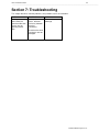
Section 7: Troubleshooting
This chapter describes common problems, their probable causes and remedies.
Problem
Possible Cause
Action
Wind measurement
failure. Both the
speed and direction
sensors are not
reporting correct
data
Blockage (trash,
leaves, branches,
bird nests) between
the wind
transducers.
Remove the
blockage.
Check that the wind
transducers are not
damaged.
Columbia Weather Systems, Inc.
40
Orion LT Weather Station
________________________________________________________________________________________________________________________
Orion LT Weather Station
41
________________________________________________________________________________________________________________________
SECTION 8: USER SUPPORT INFORMATION
This section consists of the following items:
1. One-Year Limited Warranty: Please read this document carefully.
2. Return for Repair Procedure: This procedure is for your convenience in the event you must return
your Orion LT for repair or replacement. Follow the packing instructions carefully to protect your
instrument in transit.
Limited Warranty
Columbia Weather Systems, Inc. (CWS), warrants the Orion LT Weather Station to be free from defects
in materials and/or workmanship when operated in accordance with the manufacturer’s operating
instructions, for one (1) years from date of purchase, subject to the provisions contained herein. CWS
warranty shall extend to the original purchaser only and shall be limited to factory repair or replacement of
defective parts.
EXCLUSIONS
Certain parts are not manufactured by CWS (i.e., certain purchased options, etc.) and are therefore not
covered by this warranty. These parts may be covered by warranties issued by their respective
manufacturers and although CWS will not warrant these parts, CWS will act as agent for the
administration of any such independent warranties during the term of this warranty. This warranty does
not cover normal maintenance, damage resulting from improper use or repair, or abuse by the operator.
Damage caused by lightning or other electrical discharge is specifically excluded. This warranty extends
only to repair or replacement, and shall in no event extend to consequential damages. In the event of
operator repair or replacement, this warranty shall cover neither the advisability of the repair undertaken,
nor the sufficiency of the repair itself.
THIS DOCUMENT REFLECTS THE ENTIRE AND EXCLUSIVE UNDERSTANDING OF THE PARTIES,
AND EXCEPT AS OTHERWISE PROVIDED HEREIN, ALL OTHER WARRANTIES, EXPRESS OR
IMPLIED, PARTICULARLY THE WARRANTIES OF MERCHANT ABILITY AND/OR FITNESS FOR A
PARTICULAR PURPOSE ARE EXCLUDED.
This warranty gives you specific legal rights, and you may also have other rights which vary from state to
state.
Return for Repair Procedure
1.
In the event of defects or damage to your unit, first call the Service Department Monday through
Friday, 8:30 am to 4:00 pm PST, (503) 629-0887 to determine the advisability of factory repair.
The Service Department will issue an RMA number (Return Merchandise Authorization) to help
us identify the package when received. Please place that number on the outside of the box.
2.
In the event factory service is required, return your Orion LT Weather Station as follows:
A.
Packing
Wrap the Sensor Transmitter in a plastic bag first.
Pack in original shipping carton or a sturdy oversized carton.
Use plenty of packing material.
B.
Include:
A brief description of the problem with all known symptoms.
Your phone number.
Your return street shipping address (UPS will not deliver to a P.O. box).
Write the RMA number on the outside of the box.
Columbia Weather Systems, Inc.
42
Orion LT Weather Station
________________________________________________________________________________________________________________________
C.
Shipping
Send freight prepaid (UPS recommended).
Insurance is recommended. (The factory can provide the current replacement value of
the item being shipped for insurance purposes.)
D.
Send to:
Columbia Weather Systems, Inc.
2240 NE Griffin Oaks Street, Suite 100
Hillsboro, Oregon 97124
E.
C.O.D. shipments will not be accepted.
3.
If your unit is under warranty, after repair or replacement has been completed, it will be returned
by a carrier and method chosen by Columbia Weather, Inc. to any destination within the
continental U.S.A. If you desire some other specific form of conveyance or if you are located
beyond these borders, then you must bear the additional cost of return shipment.
4.
If your unit is not under warranty, we will call you with an estimate of the charges. If approved,
your repaired unit will be returned after all charges, including parts, labor and return shipping and
handling, have been paid. If not approved, your unit will be returned as is via UPS COD for the
amount of the UPS COD freight charges.
Unit Conversion
Speed
Kilometers per hour = 1.610 x miles per hour
Knots = 0.869 x miles per hour
Meters per second = 0.448 x miles per hour
Feet per second = 1.467 x miles per hour
Orion LT Weather Station
43
________________________________________________________________________________________________________________________
Columbia Weather Systems, Inc.
2240 NE Griffin Oaks Street, Suite 100
Hillsboro, OR 97124-6463
Telephone
(503) 629-0887
Fax
(503) 629-0898
Web Site
http://www.columbiaweather.com
Email
[email protected]
Version 1.07
Printed in U.S.A.
Columbia Weather Systems, Inc.