1
PVI 1800/PVI 2500
INSTALLATION AND OPERATION MANUAL
Residential/Commercial
Grid-Tied Photovoltaic Inverter
© 2008, Solectria Renewables
Subject to Change REV A
PVI 1800/PVI 2500(Rev A)
Installation and Operation Manual
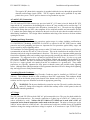
IMPORTANT SAFETY INSTRUCTIONS
This manual contains important instructions that shall be followed during installation and maintenance of
the PVI 1800/PVI 2500 Inverter.
To reduce the risk of electrical shock, and to ensure the safe installation and operation of the inverter, the
following safety symbols are used to indicate dangerous conditions and important safety instructions.
WARNING: This indicates a fact or feature very important for the safety of the user
and/or which can cause a serious hardware damage if not applied appropriately.
Use extreme caution when performing this task.
NOTE: This indicates a feature that is important either for optimal and efficient use or
optimal system operation.
EXAMPLE: This indicates an example.
SAVE THESE INSTRUCTIONS
2
DOCR-070570-A
PVI 1800/PVI 2500(Rev A)
Installation and Operation Manual
IMPORTANT SAFETY INSTRUCTIONS
All electrical installations shall be done in accordance with the local and national electrical codes
ANSI/NFPA 70, NEC. The PVI 1800 and 2500 inverters are listed to UL1741/IEEE1547 (and
comply with IEEE 62.41).
The PVI 1800/PVI 2500 contains no user serviceable parts. Do not open the inverter case as this
will damage the NEMA4, IP65 seal. Please contact Solectria Renewables or a Solectria
Renewables authorized system installer for maintenance. (See page 44 or Solectria Renewables
website, www.solren.com for Solectria Renewables contact information and authorized system
installers.)
Before installing or using the PVI 1800/PVI 2500, please read all instructions and caution
markings in this manual and on the PVI 1800/PVI 2500 unit as well as the PV modules.
Connection of the PVI 1800/PVI 2500 to the electric utility grid must be done after receiving prior
approval from the utility company and performed only by qualified personnel.
Completely cover the surface of all PV-arrays with opaque (dark) material before wiring them or
use other methods to ensure safety from shock hazard. PV arrays produce electrical energy when
exposed to light and could create a hazardous condition.
SAVE THESE INSTRUCTIONS
3
DOCR-070570-A
PVI 1800/PVI 2500(Rev A)
Installation and Operation Manual
Table of Contents
1 Introduction ...................................................................................................................
2 Installation .....................................................................................................................
2.1 Checking for Shipping Damage ............................................................................
2.2 Inverter Mounting .................................................................................................
2.3 Electrical Connection and Connection to Electrical Utility Grid,
Surge/Lightning Arrestors and Grounding Electrode Conductors ........................
3 Commissioning the Inverter and PV System ................................................................
4 Power, Ground Fault, Error LED Indicators and LCD Display....................................
4.1 Power, Ground Fault and Error LED Indicators ...................................................
4.2 The LCD Display ..................................................................................................
5 Trouble Shooting...........................................................................................................
6 Warranty........................................................................................................................
6.1 Warranty Policy ....................................................................................................
6.2 Return Material Authorization Policy ...................................................................
7 Technical Data ..............................................................................................................
5
9
9
9
14
19
21
21
23
30
33
33
36
37
Appendices ....................................................................................................................
Appendix A: Terminal assignment RS 485 / RS232 ....................................................
Appendix B: PVI 1800 / 2500 Brochure / Datasheet ...................................................
Appendix C: Example PV String Sizing Tables ..........................................................
Appendix D: Contact Information & Authorized Dealers and Installers.....................
42
42
43
43
44
4
DOCR-070570-A
PVI 1800/PVI 2500(Rev A)
Installation and Operation Manual
1 Introduction
The PVI 1800/PVI 2500 is a residential/commercial single phase, grid-tied PV inverter designed to be
inter-connected to the electric utility grid. With this manual the PVI 1800/PVI 2500 can be installed and
operated safely. This installation guide is used as reference for the commissioning and as a guideline on
how to use the inverter most effectively.
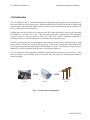
Feeding power into the grid involves conversion of the DC-voltage from the PV-array to grid compatible
AC-voltage by “inverting” DC to AC. This unit feeds power into a standard 240 VAC split phase
electrical system or two legs (phase to phase) of a 208 VAC, 3-phase commercial, industrial or
institutional facility’s electrical system that is connected to the electric utility grid.
If the PV system and inverter are providing the same amount of electrical power that the facility is using
then no power is taken from or fed into the utility grid. If the facility is using more power than the PV
system is providing, then the utility grid provides the balance of power. If the facility is using less power
than the PV system is generating, then the excess is fed into the utility grid.
Be sure to look into local regulations regarding net metering/inter-connection in your local area. Note
that some utilities need to change their revenue kWh meter for proper net metering measurement or
incentives/billing.
Photovoltaic
Array
PVI 1800/PVI 2500
Inverter
Electric Utility
Grid
Fig. 1 Grid tied inverter application
5
DOCR-070570-A
PVI 1800/PVI 2500(Rev A)
Installation and Operation Manual
The string PV concept
The use of string PV concept significantly reduces the cabling costs on a photovoltaic system. The use of
just one, two (or in some cases 3) parallel strings of PV modules in series has proven advantageous by
delivering a high operating voltage to the solar inverter. This advantage is primarily reflected in a higher
efficiency of the inverter. Careful optimization of the overall inverter system’s cost and efficiency lead to
the choice of a 400V DC maximum system voltage for the PVI 1800 and 2500 for use with 1kW to 3kW
PV arrays per inverter.
Data acquisition, display and communication
The integrated data acquisition, display and communication capability of the PVI 1800/PVI 2500 allows
comprehensive tracking of data for understanding of system performance. All error messages and
operating conditions of the PVI 1800/PVI 2500 as well as the PV system can be shown on the display.
Downloading data from the PVI 1800/PVI 2500 for analysis on a PC is also possible over the data
interfaces (RS232 or 485).
These functions allow complete and continuous monitoring of the photovoltaic system. Read-out of data
over the integrated interface and its display is only possible when the solar system is in operation.
An optional full-featured, “inverter-direct” data acquisition and logging gateway and web-based service is
available from Fat Spaniel. You can purchase this from Solectria Renewables or Fat Spaniel. It plugs
into the inverter and to the facility’s internet service.
Technical structure of the PVI 1800/PVI 2500
A high frequency switching bridge circuit operating in connection with a high frequency transformer
provides galvanic isolation of the photovoltaic system from the building’s AC power (and electrical
utility grid). The PV voltage and current are optimized in such a way that fluctuations which are caused
by differing sunlight strengths and PV module temperatures can still end up producing the maximum
possible power.
Internal regulation of the PVI 1800/PVI 2500 is achieved using microcontrollers, which control the
function of MPP (Maximum Power Point) tracking.
The input PV voltage window is designed to cover a range of 125 to 400 VDC from the PV array. This
means that many combinations of modules and strings from different manufacturers can be used.
The inverter has nearly no standby power consumption and night–time losses (0.2 W). Even when
running, the control circuit power use of the inverter is reduced to a minimum, which helps give the
inverter high operational efficiency.
The housing and heat sink for the PVI 1800/PVI 2500 is manufactured using a heavy aluminium extrusion
with an anti-corrosion finish. The housing is designed to NEMA4 and IP65 to be dust-proof and resistant to
water spray. The heat sink (and fan on the PVI 2500) are designed in such a way that operation of the
inverter is possible at ambient temperatures of -4° F (–20° C) to +131° F (+55° C) at full rated power (at
240VAC or 208VAC).
6
DOCR-070570-A
PVI 1800/PVI 2500(Rev A)
Installation and Operation Manual
The heat sink serves to conduct away heat generated from energy losses in the power electronics. Internal
temperature regulation provides protection against excessively high temperatures inside the PVI 1800/PVI
2500. The maximum power processed from the PV array is automatically reduced to limit excessive inverter
temperature.
The PVI 1800/PV2500 will only operate in parallel with the utility grid. AC grid monitoring is done by
microcontrollers set up to meet the requirements of UL1741/IEEE1547. This includes grid voltage or
frequency fluctuations outside of the required limits, anti-islanding and other limitations and requirements,
which ensure that the inverter shuts down immediately if the grid goes down, or if the grid gives surges, sags,
changes frequency or otherwise shows signs of instability. If this happens, the inverter will check the grid
and reconnect to the grid 5 minutes after the grid is back to normal. (The display then shows: “Waiting for
restart”.) Disconnecting from the grid is important to protect the electrical and utility line workers who may
be working to restore the grid as well as electricians working at a site with PV systems.
Power grid faults that will cause the PVI 1800/PVI 2500 to isolate itself from the power grid:
AC grid voltage
The grid voltage must not go outside the range of +10/-12% of the nominal 240 or 208V AC grid
voltage (as per IEEE Std 1547, § 4.2.3). The inverter will isolate itself from the power grid if these limits
are exceeded either way. The PVI 1800/2500 is factory set to 208 or 240VAC. A qualified installer can
reconfigure the grid voltage setting in the field using a computer, Solectria provided software and an
available serial communication cable.
AC grid frequency
The power grid frequency can be within a range of +0.5Hz, -0.7Hz of the nominal 60Hz grid frequency
(as per IEEE Std 1547, § 4.2.4). The inverter will isolate itself from the power grid if these permitted
limits are exceeded either way.
Another important safety feature is galvanic isolation of the utility grid and the PV array as well as ground
fault detection and interrupt (GFDI) of the PV array. The PV array negative is grounded inside the inverter
(and must not be grounded at any other point).
7
DOCR-070570-A
PVI 1800/PVI 2500(Rev A)
Installation and Operation Manual
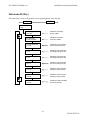
Diagram of the PVI 1800/PVI 2500 Features
1
9
2
8
3
7
4
6
5
10
Fig. 2 PVI 1800/PVI 2500 Features Diagram
(1) AC conduit fitting and conductors to building/grid (10 AWG, XHHW-2 wire) PV
(2) PV array ground fault interrupt (GFDI) fuse
(3) DC conduit fitting and conductors (10 AWG, XHHW-2 wire)
(4) Grounding Electrode Conductor connection point (on side of heat sink)
(5) Fan Connection (used on PVI 2500)
(6) RS-232/485 communication ports and caps
(7) LCD display and key pad
(8) LED indicators for basic operating status
(9) Fan assembly (on PVI 2500 only)
(10) Inverter Serial Number on bottom plate
8
DOCR-070570-A
PVI 1800/PVI 2500(Rev A)
Installation and Operation Manual
2 Installation
WARNING: Before installing the PVI 1800/PVI 2500, read all instructions and caution
markings in this manual and on the PVI 1800/PVI 2500 as well as on the photovoltaic
modules.
WARNING: Electrical installation shall be done in accordance with all local electrical
codes and the National Electrical Code (NEC), ANSI/NFPA 70.
WARNING: Connecting the PVI 1800/PVI 2500 to the electric utility grid must only be
done after receiving prior approval from the utility company and installation completed only
by qualified personnel/licensed electrician(s).
2.1 Checking for Shipping Damage
The PVI 1800/PVI 2500 inverters are thoroughly checked and tested rigorously before they are shipped.
Even though they are delivered in a rugged, heavy cardboard box, the inverters can be damaged in
shipping which is typically the fault of the shipping company.
Please inspect the inverter thoroughly after it is delivered. If any damage is seen please immediately
notify the shipping company. If there is any question about potential shipping damage, contact Solectria
Renewables. A photo of the damage may be helpful.
Do not accept unit if visibly damaged or note visible damage when signing shipping company receipt.
Report damage immediately to the shipping company. Do not remove the unit from packaging. If it is
determined that the unit must be returned, an RMA# must be obtained from Solectria Renewables.
2.2 Inverter Mounting
The PVI 1800/PVI 2500 inverter is made up of a sealed NEMA 4 /IP65 corrosion resistant aluminum
enclosure containing all electrical and electronic components.
NOTE: If the PVI 1800/PVI 2500 is mounted outside, make sure the mounting & wiring is
completed, at least to the AC and DC disconnects or junction box(es) in case of rain during
the installation process (for example overnight rain). Since the AC and DC connections are
wired to the disconnects and or junction box(es) only, there is no need to open the inverter
enclosure during hook-up. The inverter enclosure is factory sealed and must NOT be opened
at any time in the field or the NEMA4, IP65 seal will be compromised and this will void the
warranty.
9
DOCR-070570-A
PVI 1800/PVI 2500(Rev A)
Installation and Operation Manual
Notes regarding mounting and placement of the inverter
Criteria for device mounting:
Because the inverter is in a NEMA4/IP65 sealed enclosure, the inverter can be mounted outdoors.
The very longest life for the inverter can be achieved by mounting it in a clean, dry and cool location
even given the unit’s robust construction and design for efficient cooling. It is recommended to keep
the unit out of direct rain.
For optimal electrical efficiency, use the shortest possible AC and DC wires and use the maximum
allowable wire size. (10AWG minimum is recommended for all connections, both AC and DC.)
Avoid installation in close proximity to people or animals, as there is a small amount of highfrequency switching noise.
Install the inverter in an accessible location following NEC and local codes. Note NEC requirements
for disconnect door clearances and proximity to other equipment and building walls.
Although not required, installation at eye-height allows easy reading of the indicator LEDs and the
LCD display.
For optimal inverter life and performance, do not mount the inverter in direct sunlight, especially in
hot climates, although the inverter is designed to function at full power continuously in up to 131o F
(55o C) ambient temperatures. In hot climates if the unit must be mounted in direct sunlight a silver
or white metal sun-shield is highly recommended. It is recommended that the inverter be mounted on
the north (or east) side of buildings or on the north side of a PV array (which can provide some
shade). Following these guidelines can help prevent the unit from going automatic into de-rating due
to excessively high inverter case temperature.
In hot climates, the housing and heat sink can reach 176o F (80o C) and must be mounted on an
appropriate material for this temperature as well as one that meets NEC and local codes. The inverter
should not be mounted where people are likely to touch the case or heat sink due to the high potential
temperature.
CAUTION: Please follow these guidelines:
The inverter weight is about 35 lbs. (16kg). Be sure method used for fastening the unit to the wall
will safely hold this weight.
10
DOCR-070570-A
PVI 1800/PVI 2500(Rev A)
Installation and Operation Manual
The ambient temperature must be between –4o F (–20o C) and +131o F (+55o C) for full continuous,
full power operation. (The inverter will automatically reduce power or shut down to protect itself if
the ambient air temperature rises above 131o F (55o C).)
The National Electrical Code (NEC) requires that the inverter be connected to a dedicated AC circuit
and no other AC outlets or device may be connected to this circuit. See NEC Section 690.64. The
NEC also imposes limitations on the size of the inverter and the manner in with it is connected to the
utility grid. See NEC Section 690.64.
The cooling air enters at the bottom and exhausts at the top of the unit.
A minimum distance of 6 inches (152mm) must be clear above and below the inverter for ventilation.
The inverter must be mounted directly on a flat (wall) surface. (Do not mount to open studs or any
horizontal or vertical beams or struts as this can hinder proper cooling performance). The inverter
must be mounted vertically (see mounting photos).
If you are installing the inverter in a utility vault or electrical closet, the air circulation must be
sufficient for heat dissipation – provide external ventilation, to maintain an ambient condition of less
than 131o F (55o C). The ambient temperature should be kept as low as possible.
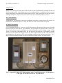
See photo and use dimensional diagrams for correct mounting of the inverter.
Typical mounting on plywood board (Sunlight Solar)
Optional panel assembly available
Painted plywood board in basement (BPVS)
Optional double panel assembly available
Fig. 3 How to mount the inverter
11
DOCR-070570-A
PVI 1800/PVI 2500(Rev A)
Installation and Operation Manual
Fig. 4 PVI 1800/PVI 2500 Dimensional Diagram
12
DOCR-070570-A
PVI 1800/PVI 2500(Rev A)
Installation and Operation Manual
Fig. 5 PVI 1800/PVI 2500 Mounting Screw Pattern
Mounting Details
Using the mounting diagram Fig. 5, for screw positions on, wall. Four #10 or #12 screws can be used.
It is recommended to use stainless steel screws, especially if used outdoors. Be sure to verify sheer and
pullout strength of anchors or other wall attachments.
NOTE: Always use all 4 mounting screws. It is easiest to layout the 4 screw mounting
pattern using Fig. 5, pre-install the 4 screws, backed out about 1/8-3/16” from the wall
surface, install the inverter, then tighten the screws. The square mounting pattern for the
screws is about 12-5/8” x 12-5/8”. A cardboard template is also included in the box with
the inverter.
13
DOCR-070570-A
PVI 1800/PVI 2500(Rev A)
Installation and Operation Manual
NOTE: The inverter is set up with pre-wired AC and DC connections to make it very easy
and quick to connect to a DC disconnect to the left of the inverter and an AC disconnect to
the right. (Connections can also be made to junction boxes.)
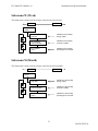
2.3 Electrical Connection and Connection To Electrical
Utility Grid
Fig. 6 Simplified electrical connection diagram
Location and Mounting the Inverter
NOTE: Choose the inverter location keeping in mind where the disconnects, and/or
junction boxes and kWh meter (if needed) will be located. It is best to mark on the wall
(or create a diagram) where all of the components are to be located. The inverter is set up
with pre-wired AC and DC connections to make it very easy and quick to connect to a
DC disconnect to the left of the inverter and an AC disconnect to the right.
Refer to Figure 2 for Locations of Features, AC and DC Wires, etc.
WARNING: All electrical installations shall be done in accordance with all local electrical
codes and the National Electrical Code (NEC), ANSI/NFPA 70.
14
DOCR-070570-A
PVI 1800/PVI 2500(Rev A)
Installation and Operation Manual
The negative DC photovoltaic connection is grounded within the inverter through the ground fault
detection and interrupt circuit (GFDI). The PV negative should not be grounded at any other
point in the system. The PV positive must never be grounded at any time.
AC and DC (PV) Connections:
The PVI 1800 and PVI 2500 inverters are pre-wired with 54” (1.35 meter) wires for both the DC (PV)
input and the AC connection to the building/grid (so that a 48” long conduit can be used leaving 6” of
conductors available for connection in the disconnect, junction box, etc.). The units are also equipped
with conduit fittings that are NEC code-compliant for use with both metallic and non-metallic flexible
1/2” conduit (the conduit fittings are included on the unit as well as the wires but the conduit needs to be
added during installation). This design allows installation and wiring of the inverter to be done without
opening the inverter.
Lightning and Surge Protection:
The inverter is designed with certain protections against surges in voltage including certification to
UL1741/IEEE1547 (including ANSI/IEEE 62.41/62.42 as required in the NY SIR), however added
protection and solid grounding provisions are important for best protection against utility surges and
surges created by indirect lightning strikes.
The installation of a Delta lightning surge arrester or other UL listed arrester of the correct specification is
recommended on both the DC and AC sides of inverter. This can be installed on the outside of the DC
disconnect and wired using the manufacturer's directions. This device gives important added protection
from indirect lightning strikes and resulting surges that provide protection beyond the inverter's UL1741
requirements. It is suggested to drive a ground rod specifically for the PV array. It is also a very good
idea to have the lightning protection system of the building checked and upgraded if needed before the
PV system is installed. (are there air conductors along the roof line of the building above the PV array?
Do you see a copper ground wire running from the air conductors to a ground rod?) These added
protections are especially important for areas prone to thunder storms and possible nearby lightning
strikes. Although these added precautions will not guarantee that there will be no damage from lightning,
they can help prevent or limit potential damage.
Grounding Electrode Conductor:
As with all PV systems, a Grounding Electrode Conductor must be installed per NEC690.47 (and
250.166). This conductor should be sized according to these NEC requirements. This conductor should
be terminated on the labeled ground point located at the bottom end of the left heat sink fin. A ¼-20
stainless steel hex cap screw should be used with an appropriate ground lug.
WARNING: The inverter should not be opened at any time. The unit is sealed at the factory
and its UL listing will no longer be valid and the warranty will be void if opened, as the seal
cannot be guaranteed.
AC Voltage:
The PVI 1800 and PVI 2500 are both 240V AC grid connected devices. They are also both suitable for
208V AC grid-connected use. For example, connection to 2 phase legs of a 208V AC, 3-phase service
(where acceptable by code). Neither unit (PVI 1800 or PVI 2500) can be used with a 120V AC
connection and no neutral connections can be made to the inverters. The units are factory pre-set for
240VAC unless ordered as a 208VAC unit. Also software and a cable are available for use by a qualified
installer to change the setting to whichever voltage is required. A PC must have a 9-pin “D” RS-232 port.
15
DOCR-070570-A
PVI 1800/PVI 2500(Rev A)
Installation and Operation Manual
Multiple Units:
Multiple PVI 1800 or PVI 2500 units can be used at the same location/facility assuming all codes are
followed including NEC, local building codes and area utility guidelines. If multiple units are used, each
inverter should have its own dedicated circuit breaker, and a PV string must only be wired to one inverter
(although multiple PV strings can be used on each inverter up to unit ratings and power levels).
AC Circuit Breakers:
A dedicated AC circuit breaker in the home or building circuit panel is required for the PV inverter. For
both the PVI 1800 and PVI 2500, a 15 Amp, 208/240V AC rated 2–circuit breaker is required.
AC and DC Disconnects:
It is recommended that the PV system AC and DC disconnects be located beside the inverter if possible
but must conform to local code for your installation. This placement will make the best use of the “prewired” inverter feature and save installation time, material and effort as well as making a simple, reliable
system. If local code requirements call for the AC and/or DC disconnect(s) to be mounted in another
location, you can consider relocating the inverter also to the required location or add a small junction box
or termination box to connect the PVI wires to building wiring going to disconnect location(s). Fig. 7
shows a typical installation with the AC and DC disconnects located on either side of the inverter.
Fig. 7 A typical PVI 1800 or PVI 2500 installation with AC and DC disconnects. (AC disconnect is
on the right, DC disconnect on the left. PVI 2500 shown.
16
DOCR-070570-A
PVI 1800/PVI 2500(Rev A)
Installation and Operation Manual
Suggested AC Disconnect: 240V AC, 30A, 2 Blade, NEMA 3R
Rain-proof NEMA 3R, no fuse
Rain-proof NEMA 3R, fusible
Rain-proof NEMA 3R, no fuse
Part Number
DU22IRB
TG3221R
TGN3321R
Manufacturer
Square D
GE
GE
Pull-out disconnect, 3R, no fuse
3800
Millbank
For some installations, code compliance may include indoor, NEMA 1 rated disconnects which are less
expensive. For whichever disconnect is selected, you will also need the proper listed ground bar kit. (No
neutral kit is needed, as no neutral line should enter the disconnect.)
Connecting the AC Inverter Wire:
WARNING: The wiring of the PV inverter’s AC and DC wires must only be done with the
building AC circuit breaker off and the PV array disconnected or covered with an opaque
material (or other method to assure the PV wiring is not live). Both AC and DC disconnects
should be off.
If the connection of the AC wires that are provided on the inverter is to be made to an AC disconnect or
junction box, mount the disconnect or junction box. (Make sure the disconnect or junction box is close
enough to the inverter so that the inverter wires will reach the disconnect or junction box via a conduit
and so that an adequate length of wire will be available inside disconnect or junction box to make the
connections/terminations to the L1, L2 and ground point.) As shipped, the conduit fittings included on
the inverter have the wires but no conduit in them. The conduit is to be fitted during installation.
Measure and cut the 1/2” liquid-tight metallic or non-metallic flexible conduit to connect between the
inverter’s AC conduit fitting and the disconnect or junction box. Next, install conduit fitting on the
disconnect or junction box. Thread the inverter’s AC wires through conduit and into disconnect or
junction box conduit fitting. Fit the conduit into the conduit fittings on inverter and disconnect or
junction box and tighten. If needed, cut off the inverter AC wires to correct length(s) inside the
disconnect or junction box. Finally, terminate inverter wires in disconnect or junction box. Black wires
are L1 and L2. Green is the AC equipment ground.
Connection Wiring To Electrical Utility Grid And Grid Impedance:
The PVI 1800/PVI 2500 must be connected to the grid with 2 conductors and a ground wire.
The grid impedance value at the connection point should be as low as possible to avoid an increase of the
AC-voltage to non-permissible values while the inverter feeds to the grid. Minimizing wiring impedance
also results in higher system efficiency.
EXAMPLE: The impedance is the sum of the electricity grid impedance at building
distribution and all impedance values of conductors and connections.
Single conductor impedance values are:
17
DOCR-070570-A
PVI 1800/PVI 2500(Rev A)
Installation and Operation Manual
Approximately 0.40 Ω for a 100 feet (76.2 m) 12 AWG conductors
Approximately 0.24 Ω for a 100 feet (76.2 m) 10 AWG conductors
Approximately 0.15 Ω for a 100 feet (76.2 m) 8 AWG conductors
Conductor impedance of < 0.40 Ω is recommended
The total impedance phase to phase of the grid plus the interconnecting AC conductors should be less
than 1.2 Ω.
Suggested DC Disconnects: 600V DC, 30A, 1-3 Circuits
Rainproof NEMA 3R
3 circuit, fused version
Rain proof NEMA 3R
Part Number
HU361RB
H361RB
THN2261RDC
Manufacturer
Square D
Square D
GE
For some installations code-compliance may include indoor, NEMA 1 rated disconnects which are also
available (typically less expensive). Also, for lower power/lower voltage configurations in which the
maximum OCV (Open Circuit Voltage) of the PV array in cold weather extremes is less than 250V DC,
per NEC690-7 (1.25X PV OCV, for example) it may be adequate to use 250V DC rated disconnects as
well.
The PVI 1800 and PVI 2500 inverters are not capable of back-feeding currents into the PV array from the
AC source including into short circuit(s) or fault(s) in the PV array or string(s). This allows some
flexibility regarding PV string configurations including parallel strings with and without string fusing. If
string fusing is required, for example on a large 2-3 string system, the fused H361RB disconnect can be
used. No separate fused PV combination is required. Refer to Square D Data Bulletin 3136DB0301
5/2003 for information. There are many one and two string configurations that do not need fusing.
PV String Configurations:
There is a huge number of PV module string combinations that will work well with the PVI 1800 and PVI
2500 inverters given the very large DC voltage range in which the inverter can operate. See string sizing
in Appendix C for several examples.
Connecting the DC (PV) Inverter Wire:
WARNING: Follow PV module manufacturer’s directions. PV-arrays produce electrical
energy when exposed to light and could create a hazardous condition. (One method used to
assure safety from shock is to completely cover the surface of all PV-arrays with opaque /
dark material before wiring them.)
WARNING: Before connecting the connectors of the PV-panel to the DC disconnect
enclosure and before connecting the DC inverter wire, check the correct polarity and
admissible PV-panel voltage between the (+) and the (-) cable connectors of the PV panel.
18
DOCR-070570-A
PVI 1800/PVI 2500(Rev A)
Installation and Operation Manual
The PV-panel open circuit voltage must be below 400V DC (Vpv < 400V DC) under all
conditions as per NEC 690-7 using multiplier for cold weather OCV. Please read the
Technical Info section and see PV string sizing table in Appendix C.
WARNING: Even when in the off position, the DC disconnect will remain live on the PV
side (“line”) when the PV modules are in daylight.
If the connection of the DC (PV) wire provided on the inverter is to be made to a DC disconnect or
junction box, mount the DC disconnect or junction box. (Make sure the disconnect or junction box is
close enough to the inverter so that the inverter’s DC wires will reach the disconnect or junction box via a
conduit and that an adequate length of wire will be available inside the disconnect or junction box to
make connections/termination to positive (+) switched terminals, negative (-) PV wire, and ground bar. It
may be convenient to use a neutral kit for terminating multiple PV negatives.)
The conduit fittings included on the inverter are open, as shipped (although the wires are inside conduit
fittings, they have no conduit in them). Measure and cut the 1/2” metallic or non-metallic flexible
conduit to go between the inverter’s DC conduit fitting and the DC disconnect or junction box. Next,
install a conduit fitting in the DC disconnect or junction box. Thread the inverter’s DC wires through the
conduit and into the DC disconnect or junction box conduit fitting. Fit the conduit into fittings and tighten
fittings. If needed, cut off inverter’s DC wires to the correct length inside the DC disconnect or junction
box. Finally, terminate inverter wires in the DC disconnect or junction box. Red wire is positive (+),
white is negative (-) and green is ground.
3 Commissioning the Inverter and PV System
The inverter is mounted, all connections are made and you are ready to power it up.
NOTE: Make sure all tools; parts, etc. are removed from the vicinity of the inverter before
turning on.
WARNING: Make a final check for correctness of all AC and DC wiring to the inverter
and in the system.
NOTE: With the PV modules connected and inverter disconnects still off, it is a good
precaution to check PV polarity once more simply by carefully using a 600V, DC rated
digital volt meter and probing the positive (+) and negative (-) PV connections in the
disconnect.
19
DOCR-070570-A
PVI 1800/PVI 2500(Rev A)
Installation and Operation Manual
Turning on the inverter:
Turn on the dedicated 2-circuit 240/208VAC circuit breaker on the home/building electrical panel
Turn on the AC disconnect
Turn on the DC disconnect
Watch the LED indicators for initialization (all three LEDs on)
Watch for blinking green LED and high frequency switching sound (this means that the inverter is
on-line and beginning to feed power into the AC circuit), the inverter is operating normally
Last, look for a steady green LED indicating the inverter has stabilized at Maximum Power Point
Operation:
The control electronics will be active as soon as DC (PV) voltage reaches 125V DC. The inverter will go
on-line with the utility/building grid when the DC voltage first exceeds 150V DC. Next, the inverter will
load the array, bringing the DC voltage down from 150V DC to no less than 125V DC.
Once there is enough PV power at 125V DC to back feed AC power switching will automatically feed
power to the grid.
Because the inverter goes completely off line at night or in dark conditions when no power can be
produced, the standby losses are less than 0.25 Watt, adding 1-2% additional energy production annually
compared to some competitor’s inverter designs that remain on all the time.
Operating states, GFDI status and error indications shown by the LED indicators, an extensive data is
shown by the LCD display which are described in chapter 4, “Power, GFDI, Error LED Indicators and
LCD Display”.
4 Power, Ground Fault, Error LED Indicators and LCD Display
The inverter operates automatically without the need for user interaction or maintenance.
The PVI 1800/PVI 2500 automatically starts feeding AC power into the grid every morning as the sun
rises, as soon as sufficient DC voltage and PV power is available. The inverter microcontroller runs
through various checks before going online with the grid and feeding power into the grid.
20
DOCR-070570-A
PVI 1800/PVI 2500(Rev A)
Installation and Operation Manual
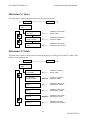
4.1 Power, Ground Fault and Error LED Indicators
There are three light-emitting diodes (LEDs) mounted on the front (upper right corner) to show the operating
condition of the inverter.
Fig. 8: Power, Ground Fault and Error Indicator
The green LED "Power" shows the current operating condition.
The red LED "Ground Fault" shows if a ground fault is present. (If there is any ground current measured the
value can be shown on the display, scrolling through the display is necessary to locate the Ground Fault
current value)
The yellow LED "Error" indicates whether there is an internal or external fault present and whether the AC
grid back-feed has been interrupted.
Description of LED symbols used to indicate LED status in this manual
LED Off
LED flashing
LED on
21
DOCR-070570-A
PVI 1800/PVI 2500(Rev A)
Installation and Operation Manual
Operating condition
Description
standby (night)
input voltage < 120 VDC
initialization
unit is being initialized
green:
waiting,
presence of valid grid conditions is
yellow:
checking grid
being checked
green:
power output to grid
normal daytime operation
yellow:
MPP or constant voltage mode
LED indicator
green:
yellow:
red:
green:
yellow:
red:
red:
red:
green:
/
yellow:
/
failure
internal or external failure, exact
description see display
red:
22
DOCR-070570-A
PVI 1800/PVI 2500(Rev A)
Installation and Operation Manual
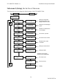
4.2 The LCD Display
The PVI 1800/PVI 2500 inverter is supplied ready to operate so there are no settings, which have to be
made by the user for fully automatic feeding of power into the grid. The device comes standard with a
display on which various types of information can be read. Settings can be made using the entry buttons
located below and information can be retrieved. All indicated measurement data is just an indication and
has tolerances of up to 8%.
Fig. 9 LCD Display
Button (ESC):
To move from the menu items into the main menu and also to leave the
Setup menu
Button ( ) and ( ): To scroll through the individual menu items or to make settings in the
Setup menu
Button (
):
To move around between the menu levels and to confirm inputs in the
Setup menu
Navigation within the display
Display illumination
Press any button to activate display illumination in Automatic mode.
Display illumination will then be automatically turned off if no key is
pressed within 30 seconds. The Setup menu also offers the option of
selecting between a constantly switched on or constantly switched off
display illumination.
Display illumination can only be activated with the <Enter> - key when in
Start-up mode.
23
DOCR-070570-A
PVI 1800/PVI 2500(Rev A)
Installation and Operation Manual
Main menu
The main menu is sub-divided into 6 menu items and each menu item contains sub-menus:
- Menu N (Now)
- Menu D (Day)
- Menu W (Week)
- Menu Y (Year)
- Menu T (Total)
- Menu S (Setup)
Description of the menu items:
Actuation of the selection buttons allows you to scroll through the main menu.
The sub-menus are then selected by pressing the <Enter> - button.
Exit the menus by pressing the <ESC> - button.
ESC
ENTER
1. Menu-N
Now (act data)
Sub Menu
2. Menu-D
Day statistic
Sub Menu
3. Menu-W
Week statistic
Sub Menu
4. Menu-M
Month statistic
Sub Menu
5. Menu-Y
Year statistic
Sub Menu
6. Menu-T
Total statistic
Sub Menu
7. Menu-S
Setup Inverter
Sub Menu
24
DOCR-070570-A
PVI 1800/PVI 2500(Rev A)
Installation and Operation Manual
Sub-menu N (Now)
This menu item is used to view current values.
ESC
ENTER
1. Menu-N
Now
1. N > AC-Power
xxxx W
Indication of the present
power output
2. N > AC-Voltage
xxxx V
Indication of the present
AC voltage
3. N > AC-Current
xxxx A
Indication of the present
AC current
4. N > AC-Frequency
xxxx Hz
Indication of the present
grid frequency
5. N > Solar Voltage
xxxx V
Indication of the present
solar array voltage
6. N > Solar Current
xxxx A
Indication of the present
solar array current
7. N > GFDI current
xxxx A
Indication of the present
ground current
8. N > Time
HH:MM:SS
Indication of the present
time
9. N > Date
WD,MM,DD,YYYY
Indication of the present
date
25
DOCR-070570-A
PVI 1800/PVI 2500(Rev A)
Installation and Operation Manual
Sub-menu D (Day)
This menu item is used to call up daily values regarding power fed to the grid.
ESC
ENTER
2. Menu-D
Day
1. D > Energy
xxxx Wh
Indication of the daily
energy output
2. D > Revenue
xxxxx.xx Dollars
Indication of the daily
revenue in dollars
3. D > AC-power-Max
xxxx W
Indication of the maximum
power output during day
4. D > AC-Voltage-Max
xxx V
Indication of the maximum
AC voltage during the day
5. D > AC-Voltage-Min
xxx V
Indication of the minimum
AC voltage during the day
6. D > AC-Current-Max
xx.x A
Indication of the maximum
AC current during the day
7. D > AC-Freq.-Max
xx.x Hz
Indication of the maximum
frequency during the day
8. D > AC-Freq.-Min
xx.x Hz
Indication of the minimum
frequency during the day
9. D > Runtime
xxx min
Indication of daily operating
time of the inverter
26
DOCR-070570-A
PVI 1800/PVI 2500(Rev A)
Installation and Operation Manual
Sub-menu W (Week)
This menu item is used to call up average values for the current week.
ESC
ENTER
3. Menu-W
Week
1. W > Energy
xxxx Wh
Indication of the weekly
energy output
2. W > Revenue
xxxxx.xx Dollars
Indication of the weekly
revenue in dollars
3. W > Runtime
xxxx h
Indication of the weekly
operating time of inverter
Sub-menu M (Month)
This menu item is used to call up average values for the current month.
ESC
ENTER
4. Menu-M
Month
1. M > Energy
xxxx kWh
Indication of the monthly
energy output
2. M > Revenue
xxxxx.xx Dollars
Indication of the monthly
revenue in dollars
3. M > Runtime
xxxx h
Indication of the monthly
operating time of inverter
27
DOCR-070570-A
PVI 1800/PVI 2500(Rev A)
Installation and Operation Manual
Sub-menu Y (Year)
This menu item is used to call up average values for the current year.
ESC
ENTER
5. Menu-Y
Year
1. Y > Energy
xxxx kWh
Indication of the annual
energy output
2. Y > Revenue
xxxxx.xx Dollars
Indication of the annual
revenue in dollars
3. Y > Runtime
xxxx h
Indication of the annual
operating time of inverter
Sub-menu T (Total)
This menu item is used to call up values concerning the power fed to the grid since the PVI 1800 or PVI
2500 was first commissioned.
ESC
ENTER
6. Menu-T
Total
1. T > Energy
xxxxxx kWh
Indication of the total
energy output
2. T > Revenue
xxxxx.xx Dollars
Indication of the total
revenue in dollars
3. T > Sol.-Vol.-Max
xxx V
Indication of the overall
maximum PV voltage
4. T > Sol.-Cur.-Max
xx.x A
Indication of the overall
maximum PV current
5. T > Sol.-Pow.-Max
xxxx W
Indication of the overall
maximum PV power
6. T > Runtime
xxxx h
Indication of the total
operating time of inverter
28
DOCR-070570-A
PVI 1800/PVI 2500(Rev A)
Installation and Operation Manual
Sub-menu S (Setup), the last line of the menu.
The Setup menu serves to change the default settings of the PVI 1800/PVI 2500.
ESC
ENTER
7. Menu-S
Setup Inverter
1. S > LCD-Contrast
setting
0 .. 9
Setting the brightness
and contrast of the LCD
display between 0 and 9
2. S > LCD-Backlight
setting
Auto/On/Off
Setting the LCD backlight
mode
3. S > Menu Mode
setting
Now .. Total
Selection of default menu
on the display
4. S > Cash per kWH
setting
xx.xx Dollars
the revenue per kWh
5. S > ID-Number
setting
6. S > Baudrate
setting
001 .. 254
2400 .. 38400
7. S > Time
setting
HH.MM:SS
8. S > Date
setting
WD,MM,DD,YYYY
ID-number of the inverter
Baudrate of the serial
connection
Setting the internal clock
Setting the date
Indication of the version
numbers of sub assemblies
9. S > Version
view
AC-Control x.x
AC control card
DC-Control x.x
DC control card
Display x.x
Display
29
DOCR-070570-A
PVI 1800/PVI 2500(Rev A)
Installation and Operation Manual
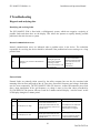
5 Troubleshooting
Diagnosis and analysing data
Identifying and resolving faults
The PVI 1800/PVI 2500 is fitted with a self-diagnostic system, which can recognise a majority of
possible faults and show these on the display. This allows the operator to rapidly identify possible
problems in the solar inverter or system.
Internal communication errors
Internal communication errors are indicated when a problem arises in the device. The technician
responsible for servicing the device should be informed if the problem has been occurring over a long
period of time.
Code
101
Designation
Hardware error, internal communication
interrupted
Condition
The device resumes
feeding the grid with
power when automatic
switching on of the
inverter reconnects it with
the power grid
Solution
The service technician
should be informed if this
error code has been seen
repeatedly or
continuously.
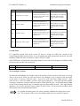
External faults
External faults are primarily faults caused by the utility company but can also be associated with
mounting of the inverter and length of the AC lines; they concern the frequency and voltage. Such faults
can also occur temporarily. The PVI 1800/PVI 2500 will, however, resume full automatic power feed
after a short interruption. If the grid frequency or voltage is more or less that values prescribed by
UL1741/IEEE1547, the inverter will not re-start for 5 minutes and will display: “wait for restart” on the
LCD display during this 5 minute period.
Code
203
204
Designation
Condition
Solution
Check the grid frequency
Grid frequency too high
The inverter switches over to
normal power/feed mode as soon
as the grid frequency returns to its
nominal value.
Grid frequency too low
The inverter switches over to
normal power/feed mode as soon
as the grid frequency returns to its
nominal value
The installer/service technician
should be informed if this
problem arises on a regular
basis
Check the grid frequency
The service technician should
be informed if this problem
30
DOCR-070570-A
PVI 1800/PVI 2500(Rev A)
Installation and Operation Manual
arises on a regular basis
Check the grid voltage
205
206
207
208
Extreme grid over-voltage
The inverter switches over to
normal power/feed mode as soon
as the power grid voltage returns
to its nominal value
Grid over-voltage
The inverter switches over to
normal power/feed mode as soon
as the grid voltage returns to its
nominal value
Grid under-voltage
The inverter switches over to
normal power/feed mode as soon
as the grid voltage returns to its
nominal value
Extreme grid under-voltage
The inverter switches over to
normal power/feed mode as soon
as the grid voltage returns to its
nominal value
The installer/service technician
should be informed if this
problem arises on a regular
basis
Check the grid voltage
The installer/service technician
should be informed if this
problem arises on a regular
basis
Check the grid voltage
The installer/service technician
should be informed if this
problem arises on a regular
basis
Check the grid voltage
The installer/service technician
should be informed if this
problem arises on a regular
basis
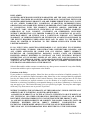
Ground Fault:
If a significant ground fault occurs in the PV array or wiring, the GFDI fuse (located on the
wiring/connector panel) may be blown. If it is, determine and repair ground fault and replace fuse with
Bussmann GBB-1 250VAC or Little Fuse 3AB 1A 250VAC 314001.
If the GDFI detects a ground fault current larger than 0.8A, error 506 will be displayed. In addition to that
the current value can be read in the display.
Code
506
Designation
Ground fault current larger than 0.8 A
Condition
The device switches off
Solution
Check installation
Weak Sunlight Condition:
Operation in weak sunlight, (for example early in the morning, when overcast or when snow is covering
most or all of the PV array) can cause the inverter to go through a cycle of trying to start and restart
several times. If you see: “Wait for restart”, “Sync to AC grid” and “Solar voltage too low”, “Solar
power too low” on the LCD display, you have weak array out put power. Look again when the sunlight
is stronger, clouds have cleared or snow has melted or fallen off of the array. It is possible that the length
of time in the morning that this type of condition appears could gradually increase. This might indicate
that there is an excessive build-up of dust or debris on the PV array. If you notice this condition, check
and wash the array for maximum performance.
It is possible that during these low power operating conditions the display shows error
301. This is normal. If this error occurs during startup, this error can also be ignored.
31
DOCR-070570-A
PVI 1800/PVI 2500(Rev A)
Installation and Operation Manual
Overview error codes
Code
Designation
Condition
The inverter resumes feeding the grid
when automatic switching on of the
inverter reconnects it with the grid
101
Hardware error, internal
communication interrupted
203
Grid frequency too high
The inverter switches to normal
power/feed mode as soon as the grid
frequency returns to its nominal value
204
Grid frequency too low
The inverter switches to normal
power/feed mode as soon as the grid
frequency returns to its nominal value
205
Extreme grid over-voltage
The inverter switches to normal
power/feed mode as soon as the grid
voltage returns to its nominal value
206
Grid over-voltage
The inverter switches to normal
power/feed mode as soon as the grid
voltage returns to its nominal value
207
Grid under-voltage
The inverter switches to normal
power/feed mode as soon as the grid
voltage returns to its nominal value
208
Extreme grid under-voltage
The inverter switches to normal
power/feed mode as soon as the grid
voltage returns to its nominal value
Internal fault on the device
301
or
The inverter switches off
blown GFDI fuse
The inverter switches off and switches
back into power feed mode when the
temperature has dropped to the normal
operating temperature
302
Excessively high temperature
506
Ground fault current > than 0.8 A The inverter switches off
Solution
The service technician should be
informed if this error code has been
seen repeatedly or continuously
Check grid frequency
The service technician should be
informed if this problem occurs on a
regular basis
Check grid frequency
The service technician should be
informed if this problem occurs on a
regular basis
Check grid voltage
The service technician should be
informed if this problem occurs on a
regular basis
Check grid voltage
The service technician should be
informed if this problem occurs on a
regular basis
Check grid voltage
The service technician should be
informed if this problem occurs on a
regular basis
Check grid voltage
The service technician should be
informed if this problem occurs on a
regular basis
Check the GFDI fuse
Please contact your installer/service
technician or Solectria Renewables. We
recommend switching off the inverter to
prevent any damage occurring to it.
Note:
this condition can occur during
operation in weak sunlight. See page 31
Check to ensure that the inverter is not
subject to direct sunlight. Please
observe the description of mounting.
Please contact your installer/service
technician or Solectria Renewables if
this measure does not eliminate the fault
Check installation
32
DOCR-070570-A
PVI 1800/PVI 2500(Rev A)
Installation and Operation Manual
6 Product Warranty & RMA Policy
6.1 Warranty Policy
The Solectria Renewables Warranty Policy is stated below.
Solectria Renewables Warranty Coverage:
Solectria Renewables Limited Warranties are provided by Solectria Renewables, LLC. ("Solectria
Renewables") and cover defects in workmanship and materials.
Duration of a Solectria Renewables Warranty Period:
The warranty period is 60 months from the date of purchase of the PVI1800 / PVI2500 by the end user or
64 months after the delivery date from Solectria Renewables to installer, dealer, distributor (merchant)
whichever is shorter. If a warranty extension has been purchased, the term is defined as extension
beyond 60 months. For example, if a 5-year extension (to 10 years total) is purchased, the term becomes
120 months from date of purchase.
If Solectria Renewables repairs or replaces a product, its warranty continues for the remaining portion of
the original Warranty Period or 90 days from the date of the return shipment to the customer, whichever
is greater.
All warranties are null and void if full payment for products and associated shipping are not received in
full and in a timely manner by Solectria Renewables.
Please contact Solectria Renewables Customer Service for further details on other products.
What will Solectria Renewables do?
Solectria Renewables will, at its option, repair or replace the defective product free of charge, provided
that you notify Solectria Renewables of the product defect within the Warranty Period for your product,
and provided that Solectria Renewables, through inspection, establishes the existence of such a defect and
that it is covered by the Limited Warranty.
Solectria Renewables will, at its option, use new and/or reconditioned parts in performing warranty repair
and building replacement products. Solectria Renewables reserves the right to use parts or products of
original or improved design in the repair or replacement. All replaced products and all parts removed
from repaired products become the property of Solectria Renewables.
Solectria Renewables will attempt to repair the unit within a reasonable time period (there is no
reimbursement for lost energy production.)
Solectria Renewables covers both parts and labor necessary to repair the product, and return shipment to
the customer via a Solectria Renewables-selected non-expedited surface freight within the contiguous
United States and Canada. Alaska and Hawaii and the Rest of The World are excluded. Contact Solectria
Renewables customer service for details on freight policy for return shipments outside of the contiguous
United States and Canada.
33
DOCR-070570-A
PVI 1800/PVI 2500(Rev A)
Installation and Operation Manual
In the event an extended warranty option has been purchased, this extended warranty only applies to
exposed outdoor locations (defined as rooftop or open/unprotected locations) if the product has been
purchased to include the gasket-sealed AC and DC disconnect option or has a protective cover around 3
sides of inverter unit (back and sides) and over the top, 4”-60” away from back and top and 30”-96” from
sides.
Obtaining Service:
If your product requires troubleshooting or warranty service, contact your merchant. If you are unable to
contact your merchant, or the merchant is unable to provide service, contact Solectria Renewables
directly at the number listed on the website in the customer service section for your product.
Direct returns may be performed according to the Solectria Renewables Return Material Authorization
Policy.
In any warranty claim, dated proof of purchase must accompany the product and the product must not
have been disassembled or modified without prior written authorization by Solectria Renewables.
Proof of purchase may be in any one of the following forms:
- The dated purchase receipt from the original purchase of the product at point of sale to the end user, or
- The dated merchant invoice or purchase receipt showing original equipment manufacturer (OEM)
status, or
- The dated invoice or purchase receipt showing the product exchanged under warranty.
What does the Solectria Renewables warranty not cover?
Solectria Renewables Limited Warranties do not cover normal wear and tear of the product or costs
related to the removal, installation, or troubleshooting of the customer's electrical systems. These
warranties do not apply to and Solectria Renewables will not be responsible for any defect in or damage
to:
a) The product if it has been misused, neglected, improperly installed, physically damaged or altered,
either internally or externally, or damaged from improper use or use in an unsuitable environment;
b) The product if it has been subjected to fire, water, generalized corrosion, biological infestations, acts of
God or input voltage that creates operating conditions beyond the maximum or minimum limits listed in
the Solectria Renewables product specifications including high input voltage from generators and
lightning
strikes;
c) The product if repairs have been done to it other than by Solectria Renewables;
d) The product if it is used as a component part of a product expressly warranted by another
manufacturer;
e) The product if its original identification (trademark, serial number) markings have been defaced,
altered, or removed;
f) The product if it has been damaged in shipping
g) Any installation and operation beyond the scope covered by relevant safety regulations (UL1741,
NEC, etc.);
Warranty Extensions:
Warranty extensions are available for additional cost (contact Solectria Renewables for information).
- 5 year extension (total warranty is 10 years)
- 10 year extension (total warranty is 15 years)
If any warranty extensions have been purchased, all the terms for the standard 5 year warranty apply
except that this warranty does not apply to PV systems that include mechanical PV array trackers. For
systems that use trackers, contact Solectria Renewables for further information.
34
DOCR-070570-A
PVI 1800/PVI 2500(Rev A)
Installation and Operation Manual
DISCLAIMER
SOLECTRIA RENEWABLES LIMITED WARRANTIES ARE THE SOLE AND EXCLUSIVE
WARRANTY PROVIDED BY SOLECTRIA RENEWABLES IN CONNECTION WITH YOUR
SOLECTRIA RENEWABLES PRODUCT AND ARE, WHERE PERMITTED BY LAW, IN LIEU
OF ALL OTHER WARRANTIES, CONDITIONS, GUARANTEES, REPRESENTATIONS,
OBLIGATIONS AND LIABILITIES, EXPRESS OR IMPLIED, STATUTORY OR OTHERWISE
IN CONNECTION WITH THE PRODUCT, HOWEVER ARISING (WHETHER BY
CONTRACT, TORT, NEGLIGENCE, PRINCIPLES OF MANUFACTURER'S LIABILITY,
OPERATION OF LAW, CONDUCT, STATEMENT OR OTHERWISE), INCLUDING
WITHOUT RESTRICTION ANY IMPLIED WARRANTY OR CONDITION OF QUALITY,
MERCHANTABILITY OR FITNESS FOR A PARTICULAR PURPOSE. ANY IMPLIED
WARRANTY OF MERCHANTABILITY OR FITNESS FOR A PARTICULAR PURPOSE TO
THE EXTENT REQUIRED UNDER APPLICABLE LAW TO APPLY TO THE PRODUCT
SHALL BE LIMITED IN DURATION TO THE PERIOD STIPULATED UNDER THIS
LIMITED WARRANTY.
IN NO EVENT WILL SOLECTRIA RENEWABLES, LLC, INCLUDING ITS SUPPLIERS,
MANUFACTURERS, VENDORS, SUBCONTRACTORS, DISTRIBUTORS, DEALERS AND
ANY OTHER AFFILIATES BE LIABLE FOR ANY SPECIAL, DIRECT, INDIRECT,
INCIDENTAL OR CONSEQUENTIAL DAMAGES, LOSSES, COSTS OR EXPENSES
HOWEVER ARISING WHETHER IN CONTRACT OR TORT INCLUDING WITHOUT
RESTRICTION ANY ECONOMIC LOSSES OF ANY KIND, ANY LOSS OR DAMAGE TO
PROPERTY, ANY PERSONAL INJURY, ANY DAMAGE OR INJURY ARISING FROM OR AS
A RESULT OF ANY USE, MISUSE OR ABUSE, OR THE (IN-) CORRECT INSTALLATION,
INTEGRATION OR OPERATION OF THE PRODUCT.
Solectria Renewables neither assumes nor authorizes any other person to assume for it any other liability
in connection with the repair or replacement or the Product.
Exclusions of the Policy:
If your product is a consumer product, federal law does not allow an exclusion of implied warranties. To
the extent you are entitled to implied warranties under federal law, to the extent permitted by applicable
law they are limited to the duration of this Limited Warranty. Some states and provinces do not allow
limitations or exclusions on implied warranties or on the duration of an implied warranty or on the
limitation or exclusion of incidental or consequential damages, so the above limitation(s) or exclusion(s)
may not apply to you. This Limited Warranty gives you specific legal rights. You may have other rights,
which may vary from state to state or province to province.
WITHOUT LIMITING THE GENERALITY OF THE FOREGOING, UNLESS SPECIFICALLY
AGREED TO BY IT IN WRITING, SOLECTRIA RENEWABLES
(a) MAKES NO WARRANTY AS TO THE ACCURACY, SUFFICIENCY OR SUITABILITY OF
ANY TECHNICAL OR OTHER INFORMATION PROVIDED IN MANUALS OR OTHER
DOCUMENTATION PROVIDED BY IT IN CONNECTION WITH THE PRODUCT; AND
(b) ASSUMES NO RESPONSIBILITY OR LIABILITY FOR LOSSES, DAMAGES, COSTS OR
EXPENSES, WHETHER SPECIAL, DIRECT, INDIRECT, CONSEQUENTIAL OR
INCIDENTAL, WHICH MIGHT ARISE OUT OF THE USE OF SUCH INFORMATION.
THE USE OF ANY SUCH INFORMATION WILL BE ENTIRELY AT THE USER'S RISK.
35
DOCR-070570-A
PVI 1800/PVI 2500(Rev A)
Installation and Operation Manual
WARNING: LIMITATIONS ON USE
Please refer to your product user manual for limitations on uses of the product. Specifically, please note
that Solectria Renewables products are not intended for use in connection with life support systems and
Solectria Renewables makes no warranty or representation in connection with any use
of the product for such purposes.
Please review our Return Merchandise Authorization Policy for returning product to Solectria
Renewables.
6.2 Return Material Authorization Policy
Please review our Return Merchandise Authorization Policy below after reviewing our Solectria
Renewables Warranty Policy.
Obtaining a required, Return Material Authorization:
Before returning a product directly to Solectria Renewables you must obtain a Return Material
Authorization (RMA) number and the correct factory "Ship To" address. Products must also be shipped
prepaid. Product shipments will be refused and returned at your expense if they are unauthorized,
returned without an RMA number clearly marked on the outside of the shipping box, if they are shipped
collect, or if they are shipped to the
wrong location.
Information Solectria Renewables needs when you are obtaining service:
1) The model names and serial number of your product
2) Information about the installation and use of the unit
3) Information about the failure and/or reason for the return
4) A copy of your dated proof of purchase.
Preparing the product for shipping:
1) Package the unit safely, preferably using the original box and packing materials. Please ensure that
your product is shipped fully insured in the original packaging or equivalent. This warranty will not apply
where the product is damaged due to improper packaging.
2) Include the following:
a. The RMA number supplied by Solectria Renewables, LLC clearly marked on the outside of the box
b. A return address to which the unit can be shipped. Post office boxes are not acceptable.
c. A contact telephone number where you can be reached during work hours.
d. A brief description of the problem.
Ship the unit prepaid to the address provided by your Solectria Renewables customer service
representative.
Returning a product from outside of the USA or Canada:
In addition to the above, you MUST include return freight funds and are fully responsible for all
documents, duties, tariffs, and deposits.
36
DOCR-070570-A
PVI 1800/PVI 2500(Rev A)
Installation and Operation Manual
7 Technical Data
Technical Information and specifications – see PVI 1800/PVI 2500
brochure for various other information and data in addition to the
information in this section of the manual. (see Appendix B for info).
Input (DC) from PV array:
Maximum open circuit voltage of PV array: 400V DC
WARNING: NEC 690-7 must be followed to calculate the maximum number of PV
modules allowed for a maximum inverter open circuit voltage (OCV) of 400V DC in
extreme cold temperatures for the installation location.
See PV string sizing chart example in Appendix C.
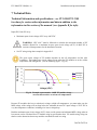
DC Current (A)
The open circuit voltage of PV modules depends on the cell temperature and the solar
irradiation. The highest open circuit voltage occurs when the PV modules are at the coldest
temperature and in bright sun. (See the following figure – Fig. 10)
8
6
at 50 deg C
4
at 20 deg C
at -20 deg C
2
0
0
10
20
30
Voltage (VDC)
Fig. 10 Example representative ~100W PV module voltage –
current characteristic at various cell temperatures
Because PV modules also have a reduction in voltage at high cell temperatures, you must make sure the
MPP voltage of the strings will not drop below the minimum inverter DC input voltage of 125V DC in
very hot temperature conditions, including wire losses/voltage drop.
Both the maximum open circuit voltage (OCV) when at cold extreme and minimum MPP voltage when at
hot extreme can be calculated for a PV module using its specification sheet. PV module string sizing can
then be used to determine how many modules can/should be used in a string.
37
DOCR-070570-A
PVI 1800/PVI 2500(Rev A)
Installation and Operation Manual
Input DC (PV) specifications for PVI 1800/PVI 2500 inverter
PVI 1800
PVI 2500
Input voltage MPP range
125V-350V DC
125V-350V DC
Maximum open circuit voltage
(under all conditions)
400V DC
400V DC
Nominal Input Current
7.3A DC
10.2A DC
Maximum input current
10A DC
14A DC
Maximum PV short-circuit current
15A DC
20A DC
Maximum input power
(inverter limited)
1980 Watt
2750 Watt
Maximum recommended
PV power (modules @ STC)
2200 Watt
3200 Watt
Ground fault detection, interrupt
yes
yes
This maximum recommended power is a nominal figure based on an array with a
relatively optimal tilt angle and orientation (south) as well as other average conditions.
Array over-sizing is used because PV modules rarely run at their STC ratings. However,
if the array is oversized too much clipping of maximum power by the inverter can occur in
optimal conditions. PV module STC conditions are rarely achieved because the cells are
usually at a higher temperature when full 1-sun is available, or when cells are at STC
temperatures, the sun's intensity is often times less than 1-sun. Because STC conditions
are rarely achieved, array over-sizing of 10-20% achieves best overall economic trade-off
with inverter and array costs. The maximum recommended power to be connected to the
inverter is very much dependent on average weather conditions, economic optimization,
tilt and of the array and orientation (for example south, or rotating array). For arrays that
are flat or nearly flat in northern location where the sun's rays are never close to being
perpendicular to the array, the array can be oversized more than these recommendations.
For locations that are hazy or cloudy for most of the year, also more array over-sizing may
be appropriate. For arrays aiming at the sun or rotating arrays that face the sun all the
time, less array over-sizing may be a good choice.
Output to AC grid connection:
The PVI 1800/PVI 2500 is designed to feed power into a standard 60Hz, 240 or 208V AC utility service
or 208V AC provided within a facility by a step down transformer (for example, from 480V AC service).
As required by NEC, there must be a dedicated 2-pole circuit breaker for the PV inverter connection.
This circuit breaker (and wiring) must have a rating of 15A. The inverter is designed to work with the
range of AC voltage for a 240VAC or 208V service defined by UL1741/IEEE1547.
38
DOCR-070570-A
PVI 1800/PVI 2500(Rev A)
Installation and Operation Manual
Output (AC) specifications for PVI 1800/PVI 2500 Inverter:
PVI 1800
PVI 2500
Continuous AC output power
1800 Watts AC
2500 Watts AC
Operating voltage range +/- 10%
240/208V AC
240/208V AC
Operating frequency range
59.3 to 60.5 Hz
59.3 to 60.5 Hz
Maximum Continuous Output Current
7.5A @ 240V AC
8.65A @ 208V AC
10.4A @ 240V AC
12A @ 208V AC
Maximum Continuous Output Power
1800 Watts AC
@ 208 & 240 VAC
2500 Watts AC
@ 208 & 240 VAC
Total Harmonic distortion (THD)
(@ full power)
< 5%
< 5%
Power Factor
> 97%
> 97%
Anti-islanding protection
per UL1741/IEEE1547
per UL1741/IEEE1547
Ground fault protection
NEC 690-5
NEC 690-5
Over current protection
inverter limited
inverter limited
Short circuit protection
per UL1741/IEEE1547
per UL1741/IEEE1547
Surge test
per UL1741/IEEE 62.41
per UL1741/IEEE 62.41
Inverter peak Efficiency*
94.1 %
94.2 %
Other specifications:
LCD Display
Included
Included
Pre-wired AC & DC (PV) Connections
Included
Included
Ambient Temperature
-4o to 140o F
(-20o to 60o C)
-4o to 140o F
(-20o to 60o C)
Temperature for full power operation
-4o to 131o F
(-20o to 55o C)
-4o to 131o F
(-20o to 55o C)
Storage Temperature
-40o to 173o F
(-40o to 70o C)
-40o to 173o F
(-40o to 70o C)
Cooling
Passive (PVI 1800)
Fan (PVI 2500)
Enclosure
NEMA 4, IP-65
NEMA 4, IP-65
Weight
34.2 lb. (15.5 kg)
36.4 lb. (16.5 kg)
*Does not include MPP tracking and other transitory phenomena.
39
DOCR-070570-A
PVI 1800/PVI 2500(Rev A)
Installation and Operation Manual
3000
2500
AC Output Power (W)
Output Power 2500
Output Power 1800
2000
1500
1000
“strike” voltage
500
0
125
175
225
275
325
375
DC Input Voltage (VDC)
Fig. 11 AC Output power of PVI 1800/PVI 2500
DC input current versus DC input voltage
Input current DC 1800W
Input current DC 2500W
16
DC Input Current (A)
14
12
10
8
6
4
2
0
125
150
175
200
225
250
275
300
325
350
375
400
DC Input Voltage (VDC)
Fig. 12 Maximum continuous DC current input for PVI 1800/PVI 2500
40
DOCR-070570-A
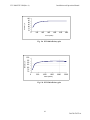
Efficiency %
PVI 1800/PVI 2500(Rev A)
Installation and Operation Manual
100
95
90
85
80
75
70
0
300
600
900
1200
1500
1800
Power (Watts)
Efficiency %
Fig. 13a PVI 1800 efficiency plot
100
95
90
85
80
75
70
0
500
1000
1500
2000
2500
Power (Watts)
Fig. 13b PVI 2500 efficiency plot
41
DOCR-070570-A
PVI 1800/PVI 2500(Rev A)
Installation and Operation Manual
Appendices
Appendix A: Terminal assignment RS-485 / RS-232:
8
1
Top view
Pin
1
2
3
4
5
6
7
8
Not used
RXD (RS232)
TXD (RS232)
GND (RS232/RS485)
TERM (RS485)
RX_B (RS485)
TX_A (RS485)
Not used
Hint! Both RJ45 connectors have the same pin-out.
Use RJ45 crimping tool such as AMP/Tyco Electronics P/N 2-231652-0
Other versions of RJ45 crimping tools are also available at stores such as Radio Shack.
+5V
Not
used
0R
TX_A
RX_B
0R
Not
used
121R
TERM
GND
Representative RS485 schematic, inside the inverter
RS232 9pol.
Pin
3 - TD
2 - RD
5 - GND
RJ45 (inverter)
Pin
2 - RXD
3 - TXD
4 - GND
RS 232 cable (schematic)
42
DOCR-070570-A
PVI 1800/PVI 2500(Rev A)
Installation and Operation Manual
Appendix B PVI 1800/PVI 2500 brochure
The brochure can also be viewed on the website: www.solren.com
Link: http://www.solren.com/downloads/PVI 1800_2500.pdf
Appendix C Example string sizing PVI 1800/PVI 2500
(Note that the chart below is only to show how string sizing charts look. Please refer to the website
version for complete and updated charts for use in all temperature zones across the country.)
Updated string sizing tables are available on the website: www.solren.com
All string sizing charts in: http://www.solren.com/products/pwreleccomp.html
Specific PVI 1800 2500 Link: http://www.solren.com/downloads/PVI 1800_2500String.pdf
43
DOCR-070570-A
PVI 1800/PVI 2500(Rev A)
Installation and Operation Manual
Appendix D - Contact Information
Solectria Renewables LLC
360 Merrimack Street
Building 9
Lawrence, Massachusetts, 01843
USA
Tel: 978.683-9700
Fax: 978.683-9702
Email: [email protected]
Website: www.solren.com
Authorized Dealers and Installers – see website: www.solren.com
Specific link: www.solren.com/distributors.html
44
DOCR-070570-A
PVI 1800/PVI 2500(Rev A)
Installation and Operation Manual
Appendix D – Certification to UL 1741 / IEEE 1547 / IEEE C62.41
45
DOCR-070570-A
PVI 1800/PVI 2500(Rev A)
Installation and Operation Manual
46
DOCR-070570-A