1
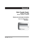
ADEMCO 6272 Series
TouchCenter Keypads
Installation and
Setup Guide
800-04701V1 2/10
Rev. A
Table of Contents
• • • • • • • • • • • • • • • • • • • • • • • • • • • • • • • •
SECTION 1 – General Information ............................................ 1–1
About the TouchCenter................................................................. 1–1
System Features........................................................................ 1–1
Security.......................................................................................... 1–1
Setup .............................................................................................. 1–1
Compatibility ................................................................................ 1–1
Safe Mode .................................................................................. 1–2
SECTION 2 – Mounting and Wiring ........................................... 2–1
Mounting the TouchCenter Mounting Plate................................. 2–1
Wiring the TouchCenter ............................................................... 2–2
SECTION 3 – Front Panel LEDs and Navigation Icons.......... 3–1
Front Panel LEDs......................................................................... 3–1
Navigation Icons ........................................................................... 3–2
Panel Fault Displays .................................................................... 3–3
SECTION 4 – Initial Setup........................................................... 4–1
Programming the Control Panel................................................... 4–1
Word List................................................................................... 4–2
TouchCenter Initialization ........................................................... 4–3
Power Up ................................................................................... 4–3
Language Selection ................................................................... 4–3
Select a Language..................................................................... 4–3
SECTION 5 - Setup........................................................................ 5–1
Setup............................................................................................. 5–1
Adjust the Brightness................................................................ 5–2
Adjust the Volume..................................................................... 5–2
Display & Audio Setup ................................................................. 5–3
Operating Modes ....................................................................... 5–3
Language Selection ................................................................... 5–4
Backlight Off Activation Time................................................... 5–5
Homepage After Time ............................................................... 5–6
Auto Slide Show After Time...................................................... 5–7
Clean Screen.............................................................................. 5–8
Routine Care.............................................................................. 5–9
Home Setup Button Layout....................................................... 5–9
Reset Home Setup Button Layout........................................... 5–10
Slide Show Setup ........................................................................ 5–11
System Setup .............................................................................. 5–12
ii
Table of Contents (Cont'd)
Central Station Setup.............................................................. 5–12
ECP Address Selection ............................................................ 5–13
Options and Operating Modes................................................. 5–13
EN50131 Display..................................................................... 5–13
Safe Mode ................................................................................ 5–15
Automatic Entry......................................................................... 5–15
Manual Entry.............................................................................. 5–15
Operating in the Safe Mode ...................................................... 5–16
Exiting the Safe Mode............................................................ 5–17
Screen Security........................................................................ 5–17
Code Authority ........................................................................ 5–19
Device Events .......................................................................... 5–20
Panel Configuration ................................................................ 5–21
User Setup .................................................................................. 5–21
User Code Setup...................................................................... 5–21
Authority Levels...................................................................... 5–22
How to Add a User .................................................................. 5–23
How to Delete a User............................................................... 5–26
How to Edit a User .................................................................. 5–27
Time/Date Setup...................................................................... 5–28
Setting Daylight Savings Time............................................. 5–28
Setting Current Time and Date............................................ 5–31
SECTION 6 - Troubleshooting .................................................... 6–1
Troubleshooting ............................................................................ 6–1
Advanced Setup ............................................................................ 6–1
Keypad Test............................................................................... 6–1
How to Access Advanced Setup.................................................. 6–1
Keypad Reset............................................................................. 6–3
Performing Diagnostic Tests......................................................... 6–4
LCD Display Test ...................................................................... 6–4
Audio Test ................................................................................. 6–5
LED Test ................................................................................... 6–6
NIGHT Setup Button Function................................................. 6–7
Output Setup Button Function ................................................. 6–8
iii
Conventions Used in This Manual
• • • • • • • • • • • • • • • • • • • • • • • • • • • • • • • •
Before you begin using this manual, it is important that you
understand the meaning of the following symbols (icons) and text
note.
notes include specific information that must be followed if you are
UL These
installing this system for a UL Listed application.
These notes include information that you should be aware of before
continuing with the installation, and which, if not observed, could result
in operational difficulties.
Note:
These text notes are provided throughout the manual to provide
informative information and shortcut tips for the installer.
Specifications
Mechanical
Width
7-1/4 inches (184mm)
Height
5 inches (127mm)
Depth
1-3/8 inches (35mm)
Electrical
Backlight OFF, Sound OFF 12V, 180mA
Backlight ON, Sound OFF
12V, 260mA
Backlight ON, Sound ON
12V, 305mA
iv
S E C T I O N
1
General Information
• • • • • • • • • • • • • • • • • • • • • • • • • • • • • • • •
In This Section
♦ About the TouchCenter
♦ Compatibility
♦ System Features
♦ Safe Mode
• • • • • • • • • • • • • • • • • • • • • • • • • • • • • • • •
About the TouchCenter
The 6272 Series graphical touch-screen keypads are Advanced User
Interface (AUI) devices, which combine security and home control.
They can be used for:
• Quick and easy security system operation
• Control of the home environment, including lights and contains
provisions for the future control of heating and air-conditioning.
Note: To the installer, see the "Important Notes" section at the back of
this guide.
UL
The home environment control feature has not been evaluated by UL.
• The 6272 Series Keypad complies with the European Standard
EN50131 and is designed to prevent unauthorized use.
• The 6272 Series devices are certified SIA-compliant devices that
meet SIA specifications for False Alarm Reduction.
System Features
Security
•
•
•
•
Arm System: – Away – Stay – Night
Disarm System
User Codes - Allows authorized user to add or delete codes
Bypass Zones
Setup
• Volume • Brightness • Diagnostics
• Keypad Emulation (Console Mode)
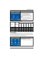
Compatibility
The below listing identifies the alarm systems that the TouchCenter
can interface with, the maximum number of TouchCenters that can
1–1
TouchCenter Installation and Setup Guide
be used with each system, and the minimum alarm panel software
revision level for compatibility.
MAXIMUM NUMBER
MINIMUM SOFTWARE
OF TOUCHCENTERS
REVISION LEVEL
ALARM SYSTEM
VISTA-15P
2
3.0
VISTA-20P
2
3.0
VISTA-20P
4
5.0
VISTA-20PS
2
3.0
VISTA-20PS
4
5.0
VISTA-21IP
4
1.0
VISTA-128BP
3
2.4
VISTA-128FBP
3
1.6
VISTA-250BP
3
2.4
VISTA-250FBP
1
1.5
VISTA-250FBP
3
2.0
• On all panels except the residential panels, you may obtain the software
revision level of the alarm panel by entering the program mode and then
entering #92 on the keypad. The second line of the keypad displays the
software revision level (w/out the decimal point).
• The keypad sound suppression feature available in some commercial panels
is not compatible with the TouchCenter.
• The ‘Voice Chime’ feature is a residential control feature only.
NOTE: If using the maximum number of 6272 Keypads, an additional
auxiliary power supply may be needed.
The message “ECP Error” will be displayed at the top of the screen (except for
the Home screen) when the TouchCenter cannot communicate with the
alarm panel. This may be caused by an incorrect ECP address in the
TouchCenter or because AUI type devices have not been enabled in the
panel. While this message is being displayed, you must use the
TouchCenter default code of “4140” any time the TouchCenter requests an
authorized code.
Safe Mode
The TouchCenter contains a Safe Mode of operation. In the rare event
that the TouchCenter cannot successfully communicate in its graphic
mode with the control panel, the Safe Mode is a backup mode that
ensures that you can communicate with your system. In this mode,
the TouchCenter operates much like a standard non-graphic keypad
so that you can control your system until the problem is corrected.
• DO NOT perform panel programming while in the Safe Mode. Performing
panel programming while in the Safe Mode may cause the panel and
TouchCenter to become out of sync.
• DO NOT use several hardwired motion detectors in high traffic locations. The
high quantity of signals received by the panel may cause the TouchCenter to
enter the Safe Mode.
1–2
S E C T I O N
2
Mounting and Wiring
• • • • • • • • • • • • • • • • • • • • • • • • • • • • • • • •
In This Section
♦ Mounting the TouchCenter Mounting Plate
♦ Wiring the TouchCenter
• • • • • • • • • • • • • • • • • • • • • • • • • • • • • • • •
Mounting the TouchCenter Mounting Plate
The TouchCenter should be mounted using the following criteria:
•
•
•
The TouchCenter must be mounted indoors
should be mounted at eye level for easy viewing by the user
should not be mounted in areas of high condensation such as
bathrooms
• should not be mounted in locations where bright light or sunlight
shines directly on the screen
To mount the TouchCenter mounting plate, complete the following
steps:
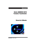
1. Detach the mounting plate from the TouchCenter by pushing it
toward the bottom of the TouchCenter.
2. Break off locking tab from mounting plate and do not discard.
(See Figure 1).
3. Locate the mounting plate over the mounting surface such that
the opening in the mounting plate is aligned with the wire/cable
access opening (in the mounting surface) while passing the
wires/cable through the opening in the mounting plate. (See
Figure 1.)
Note: The back of the TouchCenter has wire channels leading to
the bottom and the left side if surface wiring is being used.
4. Secure the mounting plate to the mounting surface using four
screws (supplied).
2–1
TouchCenter Installation and Setup Guide
MOUNTING
SCREWS (4)
(TYP)
WALL
SURFACE
BREAK OFF
LOCKING TAB
DO NOT DISCARD
WALL
MOUNTING
PLATE
6272-003-V0
Figure 1. Mounting the TouchCenter Mounting Plate
Wiring the TouchCenter
Connect TouchCenter in parallel with keypads and other peripheral
devices using the keypad data (ECP) bus. Determine wire gauge by
referring to the Wire Run Length/Gauge table below.
Wire Run Length/Gauge Table
Wire Gauge
Length
#22 gauge
150 feet
#20 gauge
240 feet
#18 gauge
350 feet
#16 gauge
550 feet
If more than one keypad is wired to one run, then the above
maximum lengths must be divided by the number of keypads on the
run (e.g., the maximum length is 75 feet if two keypads are wired on
a #22 gauge run).
Unshielded 4-conductor cable is recommended for the power/data wire.
2–2
SECTION 2: Mounting and Wiring
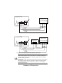
To wire, see the Summary of Connections diagrams at the back of this
guide, or the appropriate Systems Interconnection Diagram provided,
and follow the instructions below.
The TouchCenter draws up to 305mA (on models 6272CV, 6272CBV,
6272CSV . If you are planning to power it from your panel’s Aux Power
output, check your panel’s Installation and Setup Guide and verify that
this device and others do not exceed your panel's Aux Power output
capability. If it does, a supplementary power supply is needed.
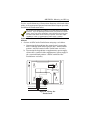
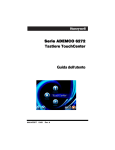
Connect the wires to the TouchCenter terminal block as
follows:
1. Connect +12VDC to the TouchCenter using step a or b below.
a. If powering the keypad from the control panel, connect the
AUX + terminal of the control panel to the + terminal block
position (+12VDC terminal of the TouchCenter (red wire)).
b. If powering the keypad from a supplementary power supply,
connect the + terminal of the supplementary power supply to
the + terminal block position (+12VDC terminal of the
TouchCenter (red wire)).
Y
DATA OUT (YELLOW)
+12VDC (RED)
G
DATA IN (GREEN)
GROUND (BLACK)
6271CV-003-V0
Figure 2. Wiring the
TouchCenter
2–3
TouchCenter Installation and Setup Guide
2. Connect ground to the TouchCenter using step a or b below.
a. If powering the keypad from the control panel, connect the
AUX – terminal of the control panel to the – terminal block
position (GND terminal of the TouchCenter (black wire)).
b. If powering the keypad from a supplementary power supply,
connect the AUX – terminal of the control panel to the (–)
terminal of the supplementary power supply (black wire).
Then, connect the (–) terminal of the supplementary power
supply to the – terminal block position (GND terminal of the
TouchCenter (black wire)).
3. Connect Data Out terminal of the control panel to the Y terminal
block position (Data In terminal of the TouchCenter (yellow
wire)).
4. Connect the Data In terminal of the control panel to the G
terminal block position (Data Out terminal of the TouchCenter
(green wire)).
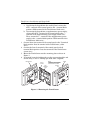
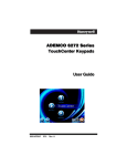
5. Mount the TouchCenter onto the mounting plate as shown in
Figure 3.
6. If required, locate the locking tab over the top mounting hole and
secure using (1) #2 x ¼" Phillips pan head screw (supplied).
TOUCHCENTER
TYPICAL
4 PLACES
WALL
MOUNTING
PLATE
NOTE
IF REQUIRED, LOCATE LOCKING
TAB OVER TOP MOUNTING HOLE
AND SECURE WITH SCREW.
SCREW
LOCKING
TAB
6272-008-V0
Figure 3. Mounting the TouchCenter
2–4
S E C T I O N
3
Front Panel LEDs
and Navigation Icons
• • • • • • • • • • • • • • • • • • • • • • • • • • • • • • • •
In This Section
♦ Front Panel LEDs
♦ Panel Fault Displays
♦ Navigation Icons
• • • • • • • • • • • • • • • • • • • • • • • • • • • • • • • •
Front Panel LEDs
The TouchCenter has three LEDs labeled - ARMED, READY and
MESSAGE. The ARMED LED is red, READY LED is green and
MESSAGE LED is yellow. Each LED's on and off state has different
meanings as described below.
LED
DESCRIPTION
*ARMED
ON – Security system is armed.
OFF – Security system is not armed.
*READY
ON – Security system is disarmed and
ready to arm.
OFF – Security system is armed or
disarmed but not ready. If disarmed, faults
or troubles are present.
MESSAGE
FLASHING – The system contains new
message(s) for the User
OFF – No new messages.
*Note: If the EN50131 Display feature is enabled, the "Armed" and "Ready"
status LEDs turn OFF until a valid user code is entered (refer to page 5-14).
3–1
TouchCenter Installation and Setup Guide
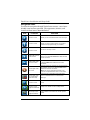
Navigation Icons
To aid in the navigation through TouchCenter screens, a set of userfriendly icons has been provided. The appearance, function, and
location of these icons is described below:
ICON
LOCATION
"Home" screen
Allows you to record and retrieve voice messages.
"Home" screen
Allows you to turn certain devices on and off (if
installed and programmed by your installer.)
"Home" screen
3–2
FUNCTION
Accesses "Security" screen.
Upper left corner of
most screens
Returns you to the TouchCenter "Home" screen.
This icon is called the Home button within the text
of this document.
Upper right corner
of most screens
Reverts to the last screen viewed. This icon is
called the Back button within the text of this
document.
Lower right corner
of screen
Displays Emergency functions (as programmed by
the installer). This icon is called the Panic button
within the text of this document.
Note: This icon is displayed and active on all
screens except while in the Clean Screen mode
and during an LCD Display test in Diagnostics.
Lower right corner
of screen (left of
Date and Time)
This icon alerts the user to a Control Panel
Message.
Lower left corner of
"Home" screen
"Slideshow" icon. Allows manual start to the slide
show.
Lower left corner of
"Home" screen
(right of Slideshow)
"Setup" icon. Allows access to Setup menus.
Lower left corner of
"Security" screen
(right of Partition)
"Voice Status" icon. Allows user to hear system
status.
SECTION 3: Front Panel LEDs and Navigation Icons
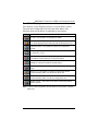
Panel Fault Displays
The “Security” screen displays an Icon(s) if a panel fault(s) occurs.
The fault Icon is displayed to the left of the Panic button. The
following Icons may be shown as applicable to your system:
ICON
MEANING
AC Loss – The system is not receiving AC power.
Bell Failure – The system bell or siren has a problem. Note: This
Icon will be displayed when interfacing with residential panels only.
Expander Failure – The system has a failure in an expansion
module.
Low Battery – The system battery, that powers the system during an
AC power loss, is low.
LRR Supervision Failure – The Long Range Radio used to communicate with the central station has a supervision failure.
Max Attempts Exceeded – The system has exceeded the maximum
attempts to communicate with the Central Station.
Pager Failure – The system cannot communicate with an assigned
pager.
Telco-1 Cut – The system is not able to communicate with the
central monitoring station over the primary phone line.
Telco-2 Cut – The system is not able to communicate with the
central monitoring station over the secondary phone line.
Wireless Failure – The system is not able to communicate with its
wireless devices.
Note: Fault Icons will scroll between all faults present on the system, if multiple
faults exist.
3–3
TouchCenter Installation and Setup Guide
3–4
S E C T I O N
4
Initial Setup
• • • • • • • • • • • • • • • • • • • • • • • • • • • • • • • •
In This Section
♦ Programming the Control
Panel
♦ TouchCenter Initialization
• • • • • • • • • • • • • • • • • • • • • • • • • • • • • • • •
Programming the Control Panel
The TouchCenter will not be fully operational unless its address in
the control panel has been enabled for an alpha console, AUI type
device, and assigned to a partition (where applicable). Refer to
“Compatibility” on page 1–1 of this document for the quantity of
TouchCenters that may be used and the required control panel
software revision level.
Note: When programming your control panel, if you change the zone
types for your emergency zones you may disable the emergency
buttons in the TouchCenter. The emergency buttons in the
TouchCenter are active for zone types 06 and 07 (Panic button), 08
(Medical Button), and 09 (Fire Button). Additionally, the Medical
button is also compatible with a zone type 15 (24-Hour Medical) for
panels that contain this zone type.
On residential control panels (VISTA-20P or equivalent), up to
four TouchCenters may be used (addresses 1, 2, 5 and 6). Addresses 1
and 2 (in field *189) are enabled by default. If the defaults have been
changed, enable these addresses (in field *189) using an alphakeypad and the Data Field Programming procedures located in the
panel Installation and Setup Guide.
On commercial control panels (VISTA-128BP, VISTA-128FBP,
or equivalent), addresses 1, 2, and one address from 3 through 30
may be used for the TouchCenter. These addresses in the control
panel are normally not defaulted for AUI type devices. To enable the
addresses you will be using for TouchCenters, use an alpha-keypad
and follow the procedures for “Device Programming” in your control
panel “Programming Guide.”
4–1
TouchCenter Installation and Setup Guide
Notes:
• If multiple TouchCenters are being used, they must be set to
addresses 1, 2, and X (where X equals any address from 3 through
30. Only one AUI type device may be assigned to an address from 3
through 30 on commercial control panels.
• The TouchCenter should not be assigned as a Master Console. If
the TouchCenter is assigned as a Master Console, partitions must
be controlled from the Partition screen or using the Console
Emulation Mode.
Word List
The 6272CV, 6272CBV and 6272CSV have the capability of
annunciating the words listed below. Please note that this listing does
not increase the vocabulary available from your panel. You must use
the listing in your alarm panel instructions for actual words that may
be requested for annunciation.
AC-Loss
Air
Alarm
Apartment
Area
Armed
Attic
Away
Baby
Back
Bar
Basement
Bathroom
Bed
Bedroom
Blower
Boiler
Building
Bypassed
Call
Carbon-Monoxide
Central
Check
Closed
Computer
Daughter's
Den
Detector
Dining
Disarmed
Disarm-System-Now
Door
4–2
Down
Downstairs
Driveway
Duct
East
Eight-Hundred
Eight
Eighteen
Eighty
Eleven
Emergency
Equipment
Exit
Factory
Father's
Fault
Fence
Fifteen
Fifty
Fire
First
Five-Hundred
Five
Floor
Forty
Four-Hundred
Four
Fourteen
Foyer
Front
Garage
Gas
Glass
Gun
Hall
Heat
House
Hundred
Inside
Instant
Kitchen
Laundry
Left
Library
Light
Living
Loading
Low-Battery
Lower
Machine
Main
Master
Medical
Mother's
Motion
Night
Nine-Hundred
Nine
Nineteen
Ninety
North
Not
Now
Off
Office
On
One
One-Hundred
Open
Outside
Panic
Patio
Phone
Police
Pool
Power
Ready-to-Arm
Rear
Right
Room
Second
Service
Seven-Hundred
Seven
Seventeen
Seventy
Shed
Shop
Side
Six-Hundred
Six
Sixteen
Sixty
Sliding
Smoke
Son's
South
Station
Stay
Storage
Supervise
Telco
Temperature
Ten
Third
Thirteen
Thirty
Three-Hundred
Three
Tool
Twelve
Twenty
Two-Hundred
Two
Up
Upper
Upstairs
Utility
West
Window
Wing
Yard
Zero
Zone
SECTION 4: Initial Setup
TouchCenter Initialization
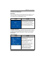
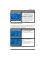
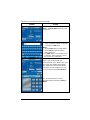
Power Up
When initially powered, the screen displays the boot sequence as it is
performed. After it is determined what services are available, the
screen displays the "Set ECP Address" screen.
SCREEN
ACTION
If the system is incorporating only one
TouchCenter, leave the address set to 1
and press the OK button. The boot-up
process will continue until completion.
If there are to be additional TouchCenter
units in the system, refer to the ECP
Address Selection paragraph in Section 5.
Language Selection
The 6272CV, 6272CBV, and 6272CSV has the functionality to display
six different languages English, European Spanish, Latin American
Spanish, French Canadian, Portuguese, or Italian with the default
being English.
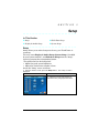
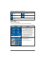
Select a Language
SCREEN
ACTION
After the initial ECP selection is set, the
"Languages" and "Blank Display" menu
screen is displayed.
From the "Languages" menu select from
English, European Spanish, Latin
American Spanish, French Canadian,
Portuguese, or Italian.
From the "Blank Display" menu select
"EN50131 Display" to meet European
Standards (refer to page 5-14).
Click OK to accept new settings.
If Cancel is selected, the keypad will
remain defaulted in English and
"EN50131" will not be enabled.
4–3
TouchCenter Installation and Setup Guide
4–4
S E C T I O N
5
Setup
• • • • • • • • • • • • • • • • • • • • • • • • • • • • • • • •
In This Section
♦
♦
Setup
Display & Audio Setup
♦
♦
Slide Show Setup
System Setup
• • • • • • • • • • • • • • • • • • • • • • • • • • • • • • • •
Setup
Setup allows you to make changes to the way your TouchCenter is
operating.
You may access Display & Audio Setup, System Setup (if enabled
by your system installer), and Slideshow Setup from the "Setup"
screen by pressing the corresponding button.
The options that can be changed are:
• Adjust the touch screen brightness
• Adjust the TouchCenter sounder volume
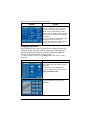
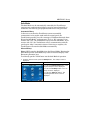
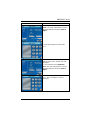
Access the "Setup" screen as follows:
1. From the "Home" screen, press the Setup button. The "Setup" screen is
displayed.
SCREEN
ACTION
2. Adjust the TouchCenter options as
described in the paragraphs that follow.
5–1
TouchCenter Installation and Setup Guide
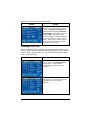
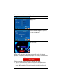
Adjust the Brightness
You may adjust the brightness settings by pressing your finger on the
slide bar associated with the "Brightness" scale and doing the following:
To increase brightness, move the slide bar above the current brightness setting.
To decrease brightness, move the slide bar below the current brightness setting.
If you have made any changes in the brightness settings, when you
exit this screen a Settings Changed! pop-up window is displayed
asking “Remember New Settings?“ Select Yes to save the change or
No to discard the change.
BRIGHTNESS
SLIDE BAR
INDICATOR
VOLUME
SLIDE BAR
INDICATOR
6272-001-V0
Brightness and Volume Control
Adjust the Volume
You may adjust the sounder volume by pressing your finger on the slide
bar associated with the "Volume" scale and doing the following:
To increase volume move the slide bar above the current volume setting.
To decrease volume move the slide bar below the current volume setting.
If you have made any changes in the volume settings, when you exit
this screen a Settings Changed! pop-up window is displayed asking
“Remember New Settings?“ Select Yes to save the change or No to
discard the change.
5–2
SECTION 5: Setup
Display & Audio Setup
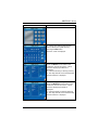
Operating Modes
Operating modes allow you to turn the TouchCenter chime mode on or
off. Additionally, you may also turn the voice mode on or off. The
operating modes provide the following features:
• Chime Mode – When selected, a request is sent to the alarm panel
requesting that the panel chime the TouchCenter whenever a change
in zone status occurs.
• Voice Mode – When selected, a request is sent to the alarm panel
requesting that the panel initiate TouchCenter voice annunciation
whenever a change in system status occurs such as Armed,
Disarmed, or Alarms.
• Voice Chime – The chime mode and voice mode are in effect. When
selected, you will get the chime beeps followed by voice annunciation.
Access the "Display and Audio Setup" screen as follows:
1. From the "Home" screen, press the Setup button.
SCREEN
ACTION
1. The "Setup" screen is displayed.
2. Press the Disp&Audio Setup button.
If enabled, the "User Authorization"
screen is displayed with the instructions
"Enter Authorized Code"
3. Enter your “Authorized Code". The
"Display and Audio Setup" screen is
displayed.
4. Touch the Chime Mode button to turn
the Chime Mode on or off. A checkmark
appears in the button when the Chime
Mode is “ON”. Note that it may take a few
seconds for the Chime Mode to take
effect.
5–3
TouchCenter Installation and Setup Guide
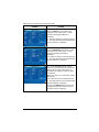
SCREEN
ACTION
5. Touch the Voice Mode button to turn
the Voice Mode on or off. A checkmark
appears in the button when the Voice
Mode is “ON”. Note that if the Chime
Mode and Voice Mode are both selected,
the Voice Chime button will automatically
be selected.
Press the “HOME” or “BACK” button after
making your selection. When the
TouchCenter exits the “Operating Modes”
screen, your selection is saved.
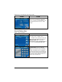
Language Selection
The TouchCenter allows you to select from six different languages,
(English, French Canadian, Italian, Portuguese, South American
Spanish and European Spanish) with the default being English.
Set the "Language Selection" feature as follows:
1. From the "Home" screen, press the Setup button. The "Setup" screen is
displayed.
SCREEN
ACTION
2. Press the Disp&Audio Setup button.
The "Display and Audio Setup" screen is
displayed.
If enabled, the "User Authorization"
screen is displayed with the instructions
"Enter Authorized Code".
3. Enter your “Authorized Code". The
"Display and Audio Setup" screen is
displayed.
5–4
SECTION 5: Setup
SCREEN
ACTION
4. To select a specified language, choose
English, French Canadian, Portuguese,
South American Spanish, Italian and
European Spanish). Once the language is
selected, the keypad will revert back to
"Home" screen with the selected language
applied.
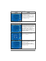
Backlight Off Activation Time
When the TouchCenter is left idle, it will automatically turn the
backlight off after the selected backlight off time has expired (unless
“Never” option is selected). To select the screen backlight time, do the
following:
SCREEN
ACTION
1. On the "Display and Audio Setup"
screen, press the Backlight Off After:
"arrow" button. A drop-down list
displaying the time period options is
displayed.
2. Select the time period option you want
by pressing it. The drop-down list closes
automatically and the selection is
displayed.
Note: Additional time intervals can be
viewed by using the up/down "arrows" to
select the time period options.
5–5
TouchCenter Installation and Setup Guide
SCREEN
ACTION
3. Press either the "Home", "Back,"
"Home Setup" or "RESET Home Setup"
buttons. A Settings Changed! pop-up
window is displayed asking “Remember
New Settings?“ Select Yes to save the
change or No to discard the change.
When the update is complete, depending
on which selection you made, ( "Home",
"Back," "Home Setup" or "RESET Home
Setup") the TouchCenter will go to it's
respective selected screen.
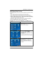
Homepage After Time
When the TouchCenter is left idle, it will automatically return to the
“Home” screen after the selected To Homepage After time has expired
(unless “Never” option is selected). To select the To Homepage After
Time, do the following:
SCREEN
ACTION
1. On the "Display and Audio Setup"
screen, press the To Homepage After
"arrow" button. A drop-down list
displaying the time period options is
displayed.
2. Select the time period option you want
by pressing it. The drop-down list closes
automatically and the selection is
displayed.
5–6
SECTION 5: Setup
SCREEN
ACTION
3. Press either the "Home", "Back,"
"Home Setup" or "RESET Home Setup"
button. A Settings Changed! pop-up
window is displayed asking “Remember
New Settings?“ Select Yes to save the
change or No to discard the change.
When the update is complete, depending
on which selection you made, ( "Home",
"Back," "Home Setup" or "RESET Home
Setup") the TouchCenter will go to it's
respective selected screen.
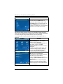
Auto Slide Show After Time
When the TouchCenter is left idle, and the Auto Slide Show After Time
is enabled, the TouchCenter will begin the slide show. To select the
Auto Slide Show After Time, do the following:
SCREEN
ACTION
1. On the "Display and Audio Setup"
screen, press Auto Slide Show After
"arrow" button. A drop-down list
displaying the time intervals is displayed.
2. Select the time interval you want by
pressing it. The drop-down list closes
automatically and the selection is
displayed.
Note: Additional time intervals can be
viewed by using the up/down "arrows" to
select the time period options.
5–7
TouchCenter Installation and Setup Guide
SCREEN
ACTION
3. Press either the "Home", "Back,"
"Home Setup" or "RESET Home Setup"
button. A Settings Changed! pop-up
window is displayed asking “Remember
New Settings?“ Select Yes to save the
change or No to discard the change.
When the update is complete, depending
on which selection you made, ("Home",
"Back," "Home Setup" or "RESET Home
Setup") the TouchCenter will go to it's
respective selected screen.
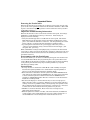
Clean Screen
With the exception of normal cleaning, the TouchCenter is maintenance
free.
Clean the TouchCenter as follows:
1. From the "Home" screen, press the Setup button. The "Setup" screen is
displayed.
SCREEN
ACTION
2. Press the Disp&Audio button. The
"Display and Audio Setup" screen is
displayed.
3. Press the CLEAN SCREEN button.
A pop-up window displays "Touch Screen
will be disabled so that you may wipe
the screen clean. Please use a damp,
soft cloth. DO NOT use any liquids,
sprays, or ammonia-based cleaners.
Press CONTINUE to disable
touchscreen."
When the "Continue" button is pressed
the message "Touch Screen Disabled
for =30 Seconds" is displayed. During
these 30 seconds the touch screen should
be wiped clean of fingerprints using a mild
soap solution and a soft cloth. When the
counter reaches zero, the window
automatically closes and the touch screen
is active.
5–8
SECTION 5: Setup
IMPORTANT: Do not use an abrasive cleaning agent or abrasive cloth
when cleaning the TouchCenter or damage to the touch screen may
occur.
The Emergency screen cannot be accessed while running in the clean
screen mode.
Routine Care
•
•
•
Treat the components of the security system as you would any other
electrical equipment. Do not slam sensor-protected doors or
windows in the vicinity of the keypad.
Keep dust from accumulating on the keypad and all protective
sensors, particularly on motion sensors and smoke detectors.
The keypad case and sensors should be carefully dusted with a dry
soft cloth. Do not spray water or any other fluid on the units.
Home Setup Button Layout
Change the location of the buttons on the display screen as follows:
1. From the "Home" screen, press the Setup button. The "Setup" screen is
displayed.
SCREEN
ACTION
2. Press the Disp&Audio button. The
"Display and Audio Setup" screen is
displayed.
3. Press the "Home Setup" button. The
user has the ability to relocate the
"Lighting", "Security", and/or "Message"
button.
4. Select the button you want to move; the
button will disappear momentarily. Select
the desired location by touching that area
on the screen where you want the button
to appear.
5–9
TouchCenter Installation and Setup Guide
SCREEN
ACTION
5. When completed, press either the
"Home", or "Back" button. A Settings
Changed! pop-up window is displayed
asking “Remember New Settings?“
Select Yes to save the change or No to
discard the change.
After selecting Yes or No, the
TouchCenter will revert back to the either
Home screen or Display and Audio Setup
screen, depending on the selection made
in Step 4.
Reset Home Setup Button Layout
To set the buttons on the Home Screen back to factory default, do the
following:
1. From the "Home" screen, press the Setup button. The "Setup" screen is
displayed.
SCREEN
ACTION
2. Press the Disp&Audio button. The
"Display and Audio Setup" screen is
displayed.
3. Press the RESET Home Setup button.
4. A "Reset the Homescreen Setup"
pop-up window is displayed prompting the
user to select Yes or No.
Press Yes to reset the button locations.
Press No to have the button layout remain
in the default locations.
5–10
SECTION 5: Setup
Slide Show Setup
The 6272 Keypad offers a Slide Show Feature. How to customize these
features will be described in this section.
To set up the Slide Show, press the Setup button on the "Home" screen
and do the following:
SCREEN
ACTION
1. Press the Slideshow Setup button.
The "Slideshow Setup" screen is
displayed.
2. Insert your personal media card. The
first image will be displayed and a list of
stored images will appear on the screen.
3. To view larger images and/or open
directories, select from the list of stored
images and press OPEN.
4. Press the TOP button to move up one
level in the directory.
5. Press the Add/Remove button to select
an image.
6. Press the CLEAR ALL button to
remove all user selected images from
slide show.
7. Select the time interval that you want to
allow between each photo being viewed
by touching the Slide Delay arrow and
select from the drop-down menu (5, 10,
15, or 20 secs).
8. Select the type of viewing transition
desired by touching the Transition arrow
and select from (Standard, Horizontal,
Vertical or Blind Effects).
9. To exit the "Slideshow" screen, press
the "Home" or "Back" button.
NOTE: When viewing the Slide Show, to exit
this feature at any time and resume keypad
operation, press anywhere on the screen.
5–11
TouchCenter Installation and Setup Guide
The following icons are displayed on the "Slideshow Setup" screen:
Preview
Previous image
Next image
Add/Remove image from slide show
Set image to home screen
wallpaper
System Setup
Central Station Setup
To Access the “Central Station” screen perform the following:
1. Press the Setup button on the “Home” screen. The “Setup” screen is displayed.
SCREEN
ACTION
2. Press the System Setup button. The
“System Setup” screen is displayed.
Press the CS Setup button and the
"CS Setup" screen is displayed.
Note: If the top of the screen is displaying
ECP Error, the ECP address in the
TouchCenter is not valid for the panel that
it is connected to. To change the ECP
address in the TouchCenter when ECP
Error is being displayed, enter the
TouchCenter default code of “4140” to
advance to the next screen.
If enabled, the "User Authorization"
screen is displayed with the instructions
"Enter Authorized Code".
3. Enter your “Authorized Code".
5–12
SECTION 5: Setup
SCREEN
ACTION
The "System Setup" screen is displayed.
ECP Address Selection
After enabling addresses in the control panel using an alpha-keypad,
power-up each TouchCenter one at a time, and set its address to one of
the addresses you enabled in the control panel. Otherwise, access the
Central Station screen then follow the procedure to change the address
on the unit.
To change the address, perform the following.
SCREEN
ACTION
1. On the “ECP Address” screen, select
the ECP address for this TouchCenter
using the Up/Dn arrows.
2. The available ECP addresses are:
1-2, 5-6 for residential controls or
1-30
for commercial controls
Press the Apply button to accept the
address setting. If the ECP address is
changed, and Apply is selected, the
TouchCenter will reset.
The "CS Setup" menu screen is
displayed.
Options and Operating Modes
The system "Options" menu allows you to enable the Display Lighting
and the EN50131 Display feature.
EN50131 Display
This feature is a European Standard designed to prevent unauthorized
users from knowing the status of the Security System. When the
EN50131 Display feature is turned ON:
• The keypad returns to the "Home" screen after 30 seconds
5–13
TouchCenter Installation and Setup Guide
and the "Armed" and "Ready" LEDs turn OFF.
The "Return to Homepage" time setting changes to 30 seconds
and the time will be non-selectable.
• The Security, Message and Lighting screen will not display
system status until an authorized user code is entered.
• The "Setup" menu will not display system status until an
authorized user code is entered.
The system "Operating Modes" menu allows you to access "Normal
Mode", "Safe Mode" and "Demo Mode".
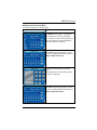
To select the "Options" and "Operating Modes" menu, do the following:
•
SCREEN
ACTION
1. On the “CS Setup” screen press the
Options button.
The "Options" and "Operating Modes"
menu is displayed.
2. From the "Options" menu touch the
"Lighting" button to turn the Lighting
option on or off.
A checkmark appears in the button when
the Lighting option is “ON”.
3. From the "Options" menu touch the
"EN50131 Display" button to turn the
EN50131 option on or off.
A checkmark appears in the button when
the EN50131 option is “ON”.
4. From the "Operating Modes" menu
select "Normal Mode" or "Safe Mode".
5. Press the Apply button to accept all
changes.
Note: DO NOT select the Demo Mode option.
This option should only be selected if instructed
to do so by factory service. When this option is
selected, the keypad will not communicate with
the control panel and any user can select
Advanced Setup screens.
5–14
SECTION 5: Setup
Safe Mode
The Safe Mode may be automatically entered by the TouchCenter
program on a communication failure or may be entered manually on
command. The following paragraphs describe these entry processes.
Automatic Entry
In the rare event that the TouchCenter cannot successfully
communicate in its graphic mode with the control panel, the
TouchCenter presents you with a message of “Problems detected. Start
Keypad in Safe Mode?” and requests a “Yes” or “No” response. If you
answer with “Yes”, the TouchCenter will go into the Safe Mode. If you
answer with “No”, the TouchCenter will try communicating with the
panel again. After 3 consecutive times of receiving no response, the
TouchCenter will enter the Safe Mode automatically.
Manual Entry
Note: ONLY enter the Safe Mode from the Normal Mode. Entering the
Safe Mode from the Demo Mode may result in incorrect display of the
Emergency Function keys.
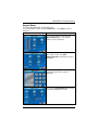
To manually put the TouchCenter into the Safe Mode of operation:
1. From the "Home" screen, press the Setup button. The "Setup" screen is
displayed.
SCREEN
ACTION
2. Press the System Setup button. The
“System Setup” screen is displayed.
3. Press the CS Setup button. The “CS
Setup” screen is displayed.
4. Press the "Options" button. The
“Operating Modes” menu screen is
displayed.
5–15
TouchCenter Installation and Setup Guide
SCREEN
ACTION
5. Select Safe Mode and then press the
Apply button.
The “Warning” message "Keypad will
reset to activate changes" is displayed.
6. Press the OK button.
The TouchCenter will reset and restart in
the Safe Mode.
Operating in the Safe Mode
While in the Safe Mode, the Home screen will display the Security
Button, Panic Button, and Message Button. A message at the bottom of
the screen will be displayed, as shown below:
This is a limited mode of operation. While in this mode:
• You can use the Security button to access the Console Emulation
Mode of operation to try to clear your faults, disarm the system, or
enter additional Alpha Keypad commands specified in your panel
5–16
SECTION 5: Setup
User and Installation Guides. You can perform almost all functions
that you can perform from a standard non-graphic alpha keypad.
• You can depress the “Panic” Button and generate Emergency
Messages as defined in the panel's home partition for this
TouchCenter.
• The Armed and Ready LEDs on the front of the TouchCenter will
indicate the TouchCenter’s home partition status.
• The Chime mode will function in the Safe Mode: however, you will
not have Voice, Voice Chime, or Message capability.
WARNING: The Slide Show feature will not start automatically in Safe Mode.
Exiting the Safe Mode
To Exit the Safe Mode:
1. Press the ! SAFE MODE ! bar. You will be presented with the following pop-up
message:
2. Press the Yes button to return to the
Normal Mode of operation. The
TouchCenter will reset and restart in the
Normal Mode.
Screen Security
The Screen Security button displays a screen that lists the various
screen classes in the TouchCenter and lists what level user has been
given access to them. To view and/or edit screen security, do the
following:
1. Press the Setup button on the “Home” screen. The “Setup” screen is displayed.
SCREEN
ACTION
2. Press the System Setup button. The
“System Setup” screen is displayed.
5–17
TouchCenter Installation and Setup Guide
SCREEN
ACTION
3. Press the CS Setup button and the
"CS Setup" screen is displayed.
4. On the “CS Setup” screen, press the
Screen Security button.
5. Enter your Authorized Code.
A listing of the classes of screens and the
user level that has access to them will be
displayed.
6. If the listing is correct, press the BACK
button to return to the “CS Setup” screen.
Note: The CS Setup screen contains a
heading of Advanced Setup, Central
Station Setup, Disp. & Audio Setup, Event
Logs, Lighting, Message, Security, or
Time/Date indicating which line was
selected for change.
If changes are necessary, select the line
to be changed and the Access Level
screen will be displayed.
5–18
SECTION 5: Setup
SCREEN
ACTION
7. Select the level of user who is to have
access to the selected class of screens
and then select the OK button. The
Screen Security screen will be redisplayed listing the change. Press the
BACK button to return to the “CS Setup”
screen.
Note: The User Levels listed on this screen
match the User Levels in commercial panels.
See the following chart for corresponding User
Levels in Residential Panels.
Residential Panels and Screen Security
No
No
No
No
No
No
Yes
Yes
No
No
No
No
Yes
Yes
No
No
No
No
Yes
Yes
Yes
No
No
No
Yes
Yes
Yes
No
Yes
No
Operator C
Operator B
Operator A
Master
Master
Normal
N/A
Guest
N/A
Manager
System Master
Partition Master
Standard User
Arm Only
Guest
Duress
Master
Authority Level
in Panel
Installer
Access Level Chosen in TouchCenter Screen Security
Matching
Authority
Level in
TouchCenter
Yes
Yes
Yes
No
Yes
No
Code Authority
The Code Authority button displays a screen that contains the User
Name and Partition Authority Level for the User Code that is entered.
To view the Code Authority level, do the following:
SCREEN
ACTION
1. On the “CS Setup” screen press the
Code Authority button. An Enter
Authorized Code screen will be displayed.
5–19
TouchCenter Installation and Setup Guide
SCREEN
ACTION
2. Enter the 4-digit User Code
corresponding to the user that you want to
obtain Authority Level information about.
An Authority Level screen containing this
information will be displayed.
3. Press the BACK button to return to the
“CS Setup Screen”.
Device Events
Your system has the ability to record various events in a history log wherein each
event is recorded with the time and date of its occurrence. The control panel must
be programmed to record various system events in installer programming mode.
To view the Device Events, perform the following:
1. From the "System Setup" screen press the CS Setup button. The "CS Setup"
screen is displayed.
SCREEN
ACTION
1. On the “CS Setup” screen press the
Device Events button.
The "Device Events" screen is displayed.
To view all items, press the up/down
arrow to scroll through the event log.
5–20
SECTION 5: Setup
Panel Configuration
The Panel Config button displays a screen that contains the
configuration of the panel that the TouchCenter is connected to. To
view the panel configuration, do the following:
SCREEN
ACTION
1. On the “CS Setup” screen press the
Panel Config button. A "Panel
Configuration" screen will be displayed
providing details of your system.
2. Press the Back button to return to the
“CS Setup” screen or if you desire to clear
the configuration from the TouchCenter
and have it reload the panel configuration
into the TouchCenter from the panel,
press the Delete button. After you press
the Delete button, a confirmation screen
is displayed.
3. Select OK to delete the configuration
or Cancel to return to the “Panel
Configuration” screen. If you select OK,
the TouchCenter will be reset and the
panel configuration will be downloaded
from the panel into the TouchCenter.
User Setup
User Code Setup
Each user must be assigned a name with a corresponding 4-digit user
code in order to gain access to various features and functions. The
5–21
TouchCenter Installation and Setup Guide
TouchCenter can hold the identity for 10 Users in its memory. If
additional Users are needed, define the additional Users using the
Console Emulation Mode.
Users for the system are programmed in a central user setup location
that provides the specific questions for authorization levels assigned to
different users. You may want these users to be the same, but there are
situations in which you may want a user to have limited capabilities.
These capabilities are defined by the Authority Level assigned to each
user.
Authority Levels
Authority levels define the system functions a particular user can
perform. Depending on the authority assigned to you, there are certain
system functions you may be prohibited from performing. The following
information describes the authority levels available in the TouchCenter
and provides the equivalent authority level name that you will find if you
are reading your alarm system manuals. The authority levels available in
the TouchCenter are as follows:
TouchCenter
Authority
Level
Installer
Master
Normal
Guest
No Access
5–22
Equivalent System Name
Functions
Residential
Systems
Commercial
Systems
Can perform all security functions except
can only disarm if code was used to arm,
can change Master Code, cannot change
other user codes, can access the Central
Station Screen options
Note: This authority level cannot be
assigned using the TouchCenter
Can perform all security functions,
add/delete users in assigned partition,
program scheduled events, and change
partition master code
Perform security functions (arm, disarm)
Installer
Installer
Partition
Master
Level 1 Master
Standard
User
Guest
Level 3
Operator A
Level 4
Operator B
N/A
N/A
Can arm the system in assigned partitions,
but cannot disarm the system unless the
system was armed with this code.
Note: Do not assign this level if Quick Arm
is enabled in the system.
Used to restrict access to a partition.
SECTION 5: Setup
Access User Setup as follows:
1. From the "Home" screen, press the Setup button. The "Setup" screen is
displayed.
SCREEN
ACTION
2. Press the System Setup button. The
"System Setup" screen is displayed.
3. Press the USER SETUP button on the
"The "System Setup" screen.
The "System Setup" screen is displayed.
How to Add a User
Add a User as follows:
SCREEN
ACTION
1. To add a user, press the ADD USER
button. The "User Authorization" screen
is displayed with the instructions "Enter
Authorized Code".
2. Enter your Authorized Code. The
“User Options” screen is displayed.
Note: The authorized code for adding
users is dependent upon the alarm panel
you are interfacing with. Check your alarm
panel Installation and Setup Guide to
determine who can add users.
5–23
TouchCenter Installation and Setup Guide
SCREEN
ACTION
3. Touch the box next to Enter User
Name. The Enter Data keyboard screen
is displayed.
4.
Type in the user name (6 characters
max.; no spaces between characters)
and press the OK button.
Notes:
• Use the Shift button for capital letters.
• Use the BS (Backspace) button to
make corrections.
• The @#$ button is not available for use
at this time. These characters cannot
be saved to the control panel.
Select the partitions, access level, and
enter a user number for this user.
If assigning this user to wireless key, enter
one of the zone numbers of the keyfob
(the wireless key must be programmed
first before it can be assigned to a user).
5. Touch the box next to User Number.
The "User Authorization" screen is
displayed with the instructions "Enter 3
Digits".
5–24
SECTION 5: Setup
SCREEN
ACTION
6. Touch the box next to Enter User
Code. The "User Authorization" screen is
displayed with the instructions "Enter 4
Digits".
7. Enter the 4-digit User Code for this
user.
The “User Options” screen is displayed
with the user’s name, number and code
displayed.
8. Touch the box next to RF Button
Zone. The "User Authorization" screen is
displayed with the instructions "Enter 3
Digits".
9. Enter the 3-digit RF Button Zone for this
user. The “User Options” screen is
displayed.
5–25
TouchCenter Installation and Setup Guide
SCREEN
ACTION
10. Press the Save button. The system
will save the configuration. When the
save is complete, the User Setup screen
is displayed with the new user’s name
shown.
How to Delete a User
Delete a User as follows:
SCREEN
ACTION
Three selections are available: add a
user, edit a user, or delete a user.
1. To delete a user, touch the circle next
to the user to be deleted and press the
DELETE USER button. The "User
Authorization" screen is displayed with the
instructions "Enter Authorized Code".
2. Enter your Authorized code. The
Confirm Delete screen is displayed.
Note: The authorized code for deleting,
adding, and editing users is dependent
upon the alarm panel you are interfacing
with. Check your alarm panel Installation
and Setup Guide to determine who can
delete, add, and edit users.
5–26
SECTION 5: Setup
SCREEN
ACTION
3. Press the appropriate button. The
User Setup screen is displayed.
How to Edit a User
Edit a User as follows:
Note: You cannot edit a User name or User number. To modify a User
name or User number, you must delete the User and re-enter User.
SCREEN
ACTION
Three selections are available: add a
user, edit a user, or delete a user.
1. To edit a user, touch the circle next to
the user to be edited and press the EDIT
USER button. The "User Authorization"
screen is displayed with the instructions
"Enter Authorized Code".
2. Enter your Authorized code. The “User
Options” screen is displayed.
Note: The authorized code for deleting,
adding, and editing users is dependent
upon the alarm panel you are interfacing
with. Check your alarm panel Installation
and Setup Guide to determine who can
delete, add, and edit users.
5–27
TouchCenter Installation and Setup Guide
SCREEN
ACTION
3. Select the options needed for this user
and press the Save button. The
configuration changes are saved and you
are returned to the User Setup screen.
Time/Date Setup
You can set the time and date from the Set Time & Date screen.
•
When the time is set it will be stored in the TouchCenter and sent
to the control panel when you press the Apply button and answer
Yes to the following prompt. Additionally, when using the
TouchCenter with a residential panel, the panel will download its
time into the TouchCenter once an hour after the clock is set.
•
If Get Time is pressed, the TouchCenter will download the time
and date from the control panel and exit the Set Time & Date
screen. Note: This button appears with residential panels only.
• If DST On (Daylight Savings Time) is selected, the TouchCenter
will adjust for Daylight Savings time at the month, week and time
chosen.
Setting Daylight Savings Time
From the "Home" screen press the "Setup" button. Press the "System
Setup" button and do the following:
SCREEN
ACTION
1. From the "System Setup" screen, press
the Time/Date Setup button. The "User
Authorization" screen is displayed with the
instructions "Enter Authorized Code".
5–28
SECTION 5: Setup
SCREEN
ACTION
2. Enter your Authorized Code.
3. Select if you want Daylight Savings
Time to affect your system clock by
touching the DST button.
The DST screen is displayed.
4. On the "Daylight Savings" screen,
press the Month "arrow" button in the
“Start DST” area of the screen. A dropdown list displaying the Months is
displayed.
5. Select the month you want by pressing
it. The drop-down list closes automatically
and the selection is displayed.
6. On the "Daylight Savings" screen,
press the Weekend "arrow" button in the
“Start DST” area of the screen. A dropdown list displaying the weeks is
displayed.
7. Select the week you want by pressing
it. The drop-down list closes automatically
and the selection is displayed.
5–29
TouchCenter Installation and Setup Guide
SCREEN
ACTION
8. On the "Daylight Savings" screen,
press the Month "arrow" button in the
“End DST” area of the screen. A dropdown list displaying the Months is
displayed.
9. Select the month you want by pressing
it. The drop-down list closes automatically
and the selection is displayed.
10. On the "Daylight Savings" screen,
press the Weekend "arrow" button in the
“End DST” area of the screen. A dropdown list displaying the weeks is
displayed.
11. Select the week you want by pressing
it. The drop-down list closes automatically
and the selection is displayed.
12. On the "Daylight Savings" screen,
press the "arrow" button to the right of the
time (1 AM or 2 AM) on the screen. A
drop-down list displaying 1 AM and 2AM
is displayed.
Make sure "DST" On is checked to enable
this feature.
13. Select the time you want by pressing
it. The drop-down list closes automatically
and the selection is displayed.
14. Press the APPLY button to save your
Daylight Savings Time setup. The “Time
and Date screen is displayed.
5–30
SECTION 5: Setup
Setting Current Time and Date
To set the current time, do the following:
SCREEN
ACTION
1. On the "Time and Date" screen, press
the Month "arrow" button. A drop-down
list displaying the months is displayed.
2. Select the current month by pressing it.
The drop-down list closes automatically
and the selection is displayed.
3. On the "Time and Date" screen, press
the Year that is being displayed. A Year
screen is displayed with the instructions to
Enter 4 digits for the year.
4. Enter the four digits for the current
year.
The window closes automatically and the
selection is displayed.
5. On the "Time and Date" screen, press
the Hour that is being displayed. An hour
screen is displayed with the instructions to
Enter 2 digits for the hour.
5–31
TouchCenter Installation and Setup Guide
SCREEN
ACTION
6. Enter the two digits for the current hour.
The window closes automatically and the
selection is displayed.
7. On the "Time and Date" screen, press
the Minutes that is being displayed. A
minute screen is displayed with the
instructions to Enter 2 digits for the
minutes.
8. Enter the two digits for the current
minute.
The window closes automatically and the
selection is displayed.
9. Select if it is AM or PM by pressing on
the AM or PM display on the screen. Each
depression switches the AM/PM display.
10. Select the day of the month by
touching the proper day in the display.
The selected date will be highlighted on
the screen.
5–32
SECTION 5: Setup
SCREEN
ACTION
11. On the "Time and Date" screen, press
the Month/Day/Year "arrow" button. A
drop-down list displaying the
Month/Day/Year display formats is
displayed.
12. Select the display format you want by
pressing it. The drop-down list closes
automatically and the selection is
displayed.
13. Select if you want a 12-hour or 24hour format for your time display by
touching the circle to the left of the 12
Hour display. A check mark in the circle
indicates a 12-hour display format.
14. On the "Time and Date" screen, press
the Apply button. A confirmation screen
is displayed.
15. Press the Yes button to save the time
changes in your security system or press
the No button to have the changes affect
the TouchCenter only.
Note: A Yes response is recommended:
A Yes response is recommended.
5–33
TouchCenter Installation and Setup Guide
5–34
S E C T I O N
6
Troubleshooting
• • • • • • • • • • • • • • • • • • • • • • • • • • • • • • • •
In This Section
♦ Troubleshooting
♦ Performing Diagnostics Tests
♦ Advanced Setup
• • • • • • • • • • • • • • • • • • • • • • • • • • • • • • • •
Troubleshooting
For troubleshooting procedures, refer to the Control Panel
Installation Guide.
Advanced Setup
Keypad Test
A series of diagnostic tests are provided that allows verification of
correct operation of the TouchCenter and its connections to the
security system. There are a total of three diagnostic tests.
How to Access Advanced Setup
To access Advanced Setup, do the following:
1. From the "Home" screen, press the Setup button. The "Setup" screen is
displayed.
SCREEN
ACTION
2. From the “Setup” screen press the
System Setup button. The "System
Setup" screen is displayed.
6–1
TouchCenter Installation and Setup Guide
SCREEN
ACTION
4. Press the Advanced Setup button on
the "System Setup" screen. The Enter
Authorized Code: authorization screen
is displayed.
5. Enter your 4-digit Installer code. The
"Advanced Setup" menu screen is
displayed.
6. Press the Keypad Test button on the
"Advanced Setup" menu screen.
The "Keypad Test" screen is displayed.
6–2
SECTION 6: Troubleshooting
Keypad Reset
To access Keypad Reset, do the following:
1. From the "Home" screen, press the Setup button. The "Setup" screen is
displayed.
SCREEN
ACTION
2. From the “Setup” screen press the
System Setup button. The "System
Setup" screen is displayed.
4. Press the Advanced Setup button on
the "Setup" screen. The Enter
Authorized Code: authorization screen is
displayed.
5. Enter your 4-digit Installer code. The
"Advanced Setup" menu screen is
displayed.
6. Press the Keypad Reset button on the
"Advanced Setup" menu screen.
6–3
TouchCenter Installation and Setup Guide
SCREEN
ACTION
If the keypad requires resetting, click OK
and the keypad will be reset. If Cancel is
pressed, keypad will not reset.
Performing Diagnostic Tests
Select any diagnostic test from the Diagnostics screen by pressing its
associated Test button. All or any individual test may be run when
you access the Diagnostics screen; however, each test must be
performed one at a time.
At any time when a test is not being performed, you can press:
• the back button to return to the previous screen, or
• the home button to return to your home page.
Once the Diagnostics screen is exited, subsequent entry to this screen
displays all test options as "Not Performed."
LCD Display Test
Perform the LCD Display Test as follows:
The Emergency screen cannot be accessed while running the LCD
Display Test.
SCREEN
ACTION
When you press the Test button
associated with the LCD Display Test, a
series of different screens will be
displayed.
6–4
SECTION 6: Troubleshooting
SCREEN
ACTION
After each type of display, you will be
asked if the display was proper.
If the response to all questions is yes, the
LCD Display Test message area of the
Diagnostics screen will display “Passed”.
Audio Test
Perform the Audio Test as follows:
SCREEN
ACTION
When you press the Test button
associated with the Audio Test, "Testing.."
is displayed in the test status column on
the "Diagnostics" screen while beeps
sound from the speaker.
At the conclusion of the test, a pop-up
"Confirmation Window" is displayed in the
center of the "Diagnostics" screen.
Within the Confirmation Window the
question "Did you hear Beeping?" is
displayed.
6–5
TouchCenter Installation and Setup Guide
SCREEN
ACTION
When you press the Yes button, "Passed"
is displayed in the test status column on
the "Diagnostics" screen.
When you press the No button, "Failed."
is displayed in the test status column on
the "Diagnostics" screen.
LED Test
Perform the LED Test as follows:
SCREEN
ACTION
1. When you press the Test button
associated with the LED Test, "Testing.."
is displayed in the test status column on
the "Diagnostics" screen while the 3 LEDs
light sequentially, top to bottom (red,
green, yellow), 5 times. At the conclusion
of the test, a pop-up "Confirmation
Window" is displayed in the center of the
"Diagnostics" screen.
2. Within the Confirmation Window the
question "Did you see chasing LED
pattern?" is displayed.
If you press the Yes button, "Passed" is
displayed in the test status column on the
"Diagnostics" screen.
If you press the No button, "Failed" is
displayed in the test status column on the
"Diagnostics" screen.
6–6
SECTION 6: Troubleshooting
NIGHT Setup Button Function
The NIGHT button can be set to arm the system in one of five arming
modes:
• Away - When selected, arms all zones with entry delay.
• Stay - When selected, arms perimeter zones with entry delay.
• Instant - When selected, arms perimeter zones without entry delay.
• Night (Residential Panels Only) – When selected, arms all perimeter
zones plus all zones listed in Zone List 5.
• Maximum - When selected, arms all zones without entry delay.
To set the NIGHT button function, do the following:
1. From the "Home" screen, press the Setup button. The "Setup" screen is
displayed.
SCREEN
ACTION
2. From the “Setup” screen press the
System Setup button. The "System
Setup" screen is displayed.
3. Press the Advanced Setup button on
the "Setup" screen. The Enter
Authorized Code: authorization screen
is displayed.
4. Enter your 4-digit Installer code. The
"Night Setup" menu screen is displayed.
5. On the “Night Setup” screen press the
Night Setup button. A "Night Setup"
screen is displayed with options for
selecting Away, Stay, Instant, Maximum
and Night.
6–7
TouchCenter Installation and Setup Guide
SCREEN
ACTION
6. Select the arming mode that will be
activated when the NIGHT button is
pressed on the "Arming" screen. Press
the Apply button to accept the setting, or
press the Back button to cancel your
selection. In either case, the TouchCenter
goes to the "CS Setup" menu screen.
Output Setup Button Function
The Output Setup function allows you to disable Output selection.
There are a maximum of five outputs that can be enabled or disabled.
To set the Output Setup button function, do the following:
1. From the "Home" screen, press the Setup button. The "Setup" screen is
displayed.
SCREEN
ACTION
2. From the “Setup” screen press the
System Setup button. The "System
Setup" screen is displayed.
3. Press the Advanced Setup button on
the "Setup" screen. The Enter
Authorized Code: authorization screen is
displayed.
4. Enter your 4-digit Installer code. The
"Advanced Setup" screen is displayed.
5. Press the Output Setup button. The
"Output Setup" screen is displayed.
To Disable the Output selection, press the
Ø symbol on the Output button.
To Enable the Output selection, press the
√ symbol on the Output button.
Press the Apply button to accept the
setting, or press the Back button to cancel
your selection.
NOTE: This is a local setting for the graphic
keypad. If user has the maximum number of
keypads on the system, and wants to disable
the same output for all, each keypad will need
to be set individually.
6–8
Important Notes:
Powering the TouchCenter
When the TouchCenter is powered from an auxiliary power supply, always apply
power to the control panel first and then the TouchCenter. Failure to observe this
sequence will result in improper operation of the TouchCenter and may result in
an ECP Error indication.
Important Troubleshooting Information
When the TouchCenter cannot communicate with the alarm panel, the message
“ECP Error” will be displayed at the top of the screen. If this message is
displayed, check the following:
• Verify that the AUI type device is enabled in the control panel, and that the
ECP address in the TouchCenter matches the address enabled in the control
panel. Use a different address for each device. (See “Programming the Control
Panel” in Section 4 of the TouchCenter Installation and Setup Guide.)
• If powering the TouchCenter from a power supply, make sure you have a
"common" ground installed (wiring connection between Power Supply "gnd"
and panel "Aux. power neg").
While an ECP Error message is being displayed, you must use the TouchCenter
access code of “4140” any time the TouchCenter requests an authorized code. Once
communication has been restored, then use the standard panel installer code for
all installer functions.
Programming with the TouchCenter
We recommend that you use either a standard alpha keypad or the TouchCenter
in Console Emulation Mode when programming the control panel. When in the
Console Mode, the TouchCenter emulates an alpha keypad and the programming
of the panel is performed following the procedures provided in your panel’s
Installation and Setup Guide.
General Notes
• You may check to see whether the Chime Mode is ON or OFF by viewing the
TouchCenter Operating Modes screen as described in “Operating Modes” in
Section 5 of the TouchCenter Installation and Setup Guide.
• The TouchCenter is defaulted to arm the system in the STAY INSTANT mode
when arming the system using the NIGHT button. To change the TouchCenter
so that it arms the system in a different mode when the NIGHT button is
pressed, see “NIGHT Setup Button Function” in Section 6 of the TouchCenter
Installation and Setup Guide.
• Note that some displays on the TouchCenter may not have enough space to
display the whole name of a partition. When this occurs, the display will show
as many characters as possible starting at the beginning of the partition name.
We recommend that the partition name be kept to a maximum of 7 characters
to ensure the “H” which indicates the home partition may be seen.
• “Exit Error” and “Auto Arm Alert, Please Leave Now” messages are not
displayed by the TouchCenter.
• When the system has 6150Vs or 6160Vs, and 6271Vs attached, the Additional
Console setting in the 6150Vs (displayed as A on the 6150V) must be set to 1
and the Additional Console setting in the 6160Vs must be set to Yes.
Commercial System Notes
• If the Aux Relay function is set for alarm silenced by User Code + # + 67, this
command may only be entered in the console emulation mode.
• Do not use the common lobby logic function.
• If fields 2*22 (Display Fire Alarms of other Partitions), 2*23 (Display Burg &
Panic of other Partitions), or 2*24 (Display Troubles of other Partitions) are
enabled, the zones that created the conditions cannot be viewed. You must go to
that zone's home partition to view.
• If field 1*11 (Zone Bypass After Disarm) is enabled, you must use the
TouchCenter’s Console Emulation Mode and the commands “Code” + “64”
(unbypass all) or “Code” + “6” + “Zone Number” (unbypass zone) to remove zone
bypasses.
• The First to Alarm Display Lock feature (field 1*10) is not supported by the
TouchCenter.
• RF Low Battery messages are not supported by the TouchCenter except in the
Show Zones screen where a Battery Icon will be displayed for the zone with the
low battery.
• On multi-partition systems when the user has access to multiple partitions and
arms the system, the TouchCenter will always ask the arm multiple partitions
question regardless of the “Arm Multi-Partitions” setting.
Residential System Notes
• If the Clean Me option is set, when the maintenance signal is received you will
get a “Fire Maintenance” message and the Display Faults button will be shown.
However, if you display the faults, zone 1 will not be shown as a faulted zone.
• If RF Jam Reports are selected and RF Jam is detected, the User Authorization
screen will display “Trouble ZN100 RF Receiver”. If you enter the console
emulation mode, the display will show “Check 90 RF Receiver Jam”.
• Do not use the Custom Word reminder feature.
User Related Notes
• Users added to the system using the TouchCenter graphic user screen must be
deleted from the TouchCenter using the graphic screen as well. Deleting users
from the panel by any other means (alpha keypad, console emulation mode, or
Compass downloader) will not automatically delete them from the
TouchCenter.
• If the panel has exit tones enabled and you arm the system in the Away mode,
the TouchCenter will beep continuously throughout the exit period.
Use the console emulation mode for the following functions:
- Programming more than 10 system users.
- Programming the Pager report option for users of residential control panels (e.g.,
VISTA-15P and VISTA-20P).
- Special Function Key operations (such as macros or single-button paging).
- End-User Scheduling.
- To check for an “Alarm Cancelled” message if this feature has been enabled in
the system.
TOUCHCENTER
CONTROL
TERMINAL STRIP
Y
AUX
G
+
AUX DATA DATA
IN
OUT
_
BLACK
RED
GREEN
YELLOW
POWERING THE TOUCHCENTER KEYPAD FROM THE CONTROL
TOUCHCENTER
CONTROL
TERMINAL STRIP
Y
SUPPLEMENTARY
POWER SUPPLY
G
+
BLACK
AUX
_
+
AUX DATA DATA
IN
OUT
_
BLACK
RED
GREEN
YELLOW
POWERING THE TOUCHCENTER FROM A SUPPLEMENTARY POWER SUPPLY
UL
6271CV-008-V0
Use a UL Listed, battery-backed supply for UL installations. The battery supplies
power to these keypads in case of AC power loss. The battery-backed power
supply should have enough power to supply the keypads with the UL required
minimum standby power time.
IMPORTANT: Keypads powered from supplies that do not have a backup battery
will not function if AC power is lost. Make sure to power at least one keypad in
each partition from the control’s auxiliary power output or UL Listed battery
backed up power supply.
Summary of Connections
For the latest warranty information, please go to:
www.honeywell.com/security/hsc/resources/wa
2 Corporate Center Drive, Suite 100
P.O. Box 9040
Melville, NY 11747
Copyright © 2009 Honeywell International Inc.
www.honeywell.com/security
Ê800-04701V1tŠ
800-04701V1 2/10
Rev. A