1
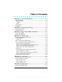
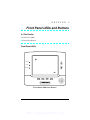
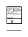
7RXFK6FUHHQ
.H\SDG
,QVWDOODWLRQDQG
6HWXS*XLGH
ARMED
READY
MESSAGE
HOME
FUNC
PANIC
BACK
®
K0977
4/03
WWW.DIYALARMFORUM.COM
WWW.DIYALARMFORUM.COM
Table of Contents
x x x x x x x x x x x x x x x x x x x x x x x x x x x x x x x x
SECTION 1 – General Information.............................................. 1–1
About the 6270 ................................................................................. 1–1
System Features .............................................................................. 1–1
Security......................................................................................... 1–1
Setup ............................................................................................. 1–1
Compatibility ................................................................................... 1–2
ECP Error......................................................................................... 1–2
SECTION 2 – Mounting and Wiring ............................................ 2–1
Mounting the 6270........................................................................... 2–1
Wiring the 6270 ............................................................................... 2–2
SECTION 3 – Front Panel LEDs and Buttons ........................... 3–1
Front Panel LEDs............................................................................ 3–1
Front Panel Buttons ........................................................................ 3–2
SECTION 4 – Initial Setup ............................................................. 4–1
Programming the Control Panel..................................................... 4–1
6270 Initialization ........................................................................... 4–2
Power Up ...................................................................................... 4–2
How to Change the ECP Address ................................................... 4–2
How to Access the Central Station Screen..................................... 4–3
How to Select System Options .................................................... 4–6
How to Set the NIGHT Setup Button Function......................... 4–7
How to View and Edit Screen Security....................................... 4–8
How to View the Panel Configuration ........................................ 4–9
6270 Setup...................................................................................... 4–10
How to Adjust the Touch Screen Contrast ............................... 4–11
How to Adjust the Volume......................................................... 4–12
How to Select Screen Saver Activation Time ........................... 4–13
How to Set the Time and Date .................................................. 4–14
Setting Chime Mode On/Off.......................................................... 4–15
SECTION 5 – User Codes................................................................ 5–1
Introduction to User Code Setup .................................................... 5–1
How to Access User Setup............................................................... 5–1
How to Add a User ....................................................................... 5–3
How to Delete a User ................................................................... 5–5
How to Edit a User....................................................................... 5–6
SECTION 6 – Maintenance ............................................................ 6–1
About 6270 Maintenance ................................................................ 6–1
iii
WWW.DIYALARMFORUM.COM
How to Clean the 6270 .................................................................... 6–1
Routine Care .................................................................................... 6–3
SECTION 7 – Troubleshooting...................................................... 7–1
Troubleshooting ............................................................................... 7–1
Diagnostics ....................................................................................... 7–1
About Diagnostics ........................................................................ 7–1
How to Access the Diagnostics .................................................... 7–1
Performing Diagnostics ................................................................... 7–3
LCD Display Test......................................................................... 7–3
Audio Test..................................................................................... 7–6
LED Test....................................................................................... 7–7
SECTION 8 – Specifications .......................................................... 8–1
Specifications ................................................................................... 8–1
SECTION 9 – Index .......................................................................... 9–1
iv
WWW.DIYALARMFORUM.COM
Conventions Used in This Manual
x x x x x x x x x x x x x x x x x x x x x x x x x x x x x x x x
Before you begin using this manual, it is important that you
understand the meaning of the following symbols (icons) and text
note.
notes include specific information that must be followed if you are
UL These
installing this system for a UL Listed application.
These notes include information that you should be aware of before
continuing with the installation, and which, if not observed, could result
in operational difficulties.
Note:
These text notes are provided throughout the manual to provide
informative information and shortcut tips for the installer.
v
WWW.DIYALARMFORUM.COM
vi
WWW.DIYALARMFORUM.COM
S E C T I O N
1
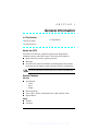
General Information
x x x x x x x x x x x x x x x x x x x x x x x x x x x x x x x x
In This Section
♦ About the 6270
♦ Compatibility
♦ System Features
x x x x x x x x x x x x x x x x x x x x x x x x x x x x x x x x
About the 6270
The 6270 is an intuitive, graphical touch-screen keypad that
combines security and home control. The 6270 can be used for:
x
x
x
Quick and easy security system operation
Messages
Control of the home environment, including lights and contains
provisions for the future control of heating and air-conditioning.
UL The home environment control feature has not been evaluated by UL.
System Features
Security
x Arm System
x
x
x
–
Away
–
Stay
–
Night
Disarm System
User Codes - Allows authorized user to add or delete codes
Bypass Zones
Setup
x Volume
x Contrast
1–1
WWW.DIYALARMFORUM.COM
6270 Installation and Setup Guide
x
x
Diagnostics
Keypad Emulation
Compatibility
The below listing identifies the alarm systems that the 6270 can
interface with, the maximum number of 6270s that can be used with
each system, and the minimum alarm panel software revision level
for compatibility.
ALARM SYSTEM
VISTA-20PS
VISTA-128BP
VISTA-128FBP
VISTA-250BP
VISTA-250FBP
FA168CPS
FA1660C
FA1700C
MAXIMUM NUMBER
OF 6270s
2
3
3
3
1
2
3
1
MINIMUM SOFTWARE
REVISION LEVEL
All Levels
2.4
1.6
2.4
1.5
All Levels
2.4
1.5
On all panels except the VISTA-20PS and FA168CPS, you may obtain
the software revision level of the alarm panel by entering the program
mode and then entering #92 on the keypad. The second line of the
keypad displays the software revision level (without the decimal point).
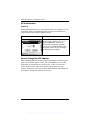
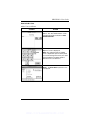
ECP Error
The message “ECP Error” will be displayed at the top of the screen (except for
the Home screen) when the 6270 cannot communicate with the alarm panel.
This may be caused by and incorrect ECP address in the 6270 or because AUI
type devices have not been enabled in the panel. While this message is being
displayed, you must use the 6270 default code of “4140” any time the 6270
requests an authorized code.
1–2
WWW.DIYALARMFORUM.COM
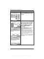
S E C T I O N
2
Mounting and Wiring
x x x x x x x x x x x x x x x x x x x x x x x x x x x x x x x x
In This Section
♦ Mounting the 6270
♦ Wiring the 6270
x x x x x x x x x x x x x x x x x x x x x x x x x x x x x x x x
Mounting the 6270
The 6270 should be mounted using the following criteria:
x
x
The 6270 must be mounted indoors, and
should be mounted at eye level for easy viewing by the user.
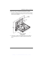
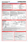
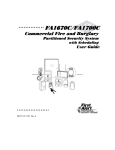
To mount the 6270, see Figure 1 and complete the following steps:
1. Detach the case back by pushing up into the two tabs located at
the bottom of the 6270 with the blade of a screwdriver while
pulling the case back and case front apart.
2. Locate the case back over the mounting surface such that the
opening in the case back is aligned with the wire/cable access
opening (in the mounting surface) while passing the wires/cable
through the opening in the case back.
3. Secure the case back to the mounting surface using four screws
(supplied).
Prior to attaching the case front to the case back, be sure to wire the
6270 as described in the "Wiring the 6270" paragraph in this section.
2–1
WWW.DIYALARMFORUM.COM
6270 Installation and Setup Guide
MOUNTING
SCREWS (4)
(TYP)
CASE
FRONT
D
ARME
Y
READ
WALL OR
MOUNTING
SURFACE
AGE
BACK
MESS
C
PANI
FUNC
HOME
CASE
BACK
6270-003-V0
Figure 1. Mounting the 6270
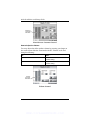
Wiring the 6270
Connect 6270 in parallel with keypads and other peripheral devices
using the keypad data (ECP) bus. To wire, see the Summary of
Connections diagrams at the back of this guide, or the appropriate
Systems Interconnection Diagram provided, and follow the
instructions below.
UL
The 6270 must be used in conjunction with a second keypad that is
powered by the control panel.
x Use a Listed Class 2 power supply suited for the application.
x
Unshielded 4-conductor cable is recommended for the power/data wire.
2–2
WWW.DIYALARMFORUM.COM
SECTION 2: Mounting and Wiring
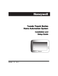
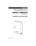
Connect the wires to the 6270 terminal block as follows:
1. The 6270 has holding clips on the case back to hold the case front
while you are wiring the unit. Hang the case front on the holding
clips as shown in Figure 2.
WALL OR
MOUNTING
SURFACE
CASE
BACK
Y
+
G
CASE
FRONT
6270-009-V0
Figure 2. Wiring
Preparation
2. Connect the + terminal of the supplementary power supply to
terminal block position 2 (+12VDC terminal of the 6270 (red
wire)).
2–3
WWW.DIYALARMFORUM.COM
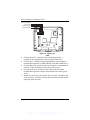
6270 Installation and Setup Guide
DATA OUT (YELLOW)
+12VDC (RED)
GROUND (BLACK)
+
+
+
+
+
+
DATA IN (GREEN)
Y +
G
6270-002-V0
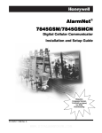
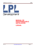
Figure 3. Wiring the
6270
3. Connect the AUX – terminal of the control panel to the (–)
terminal of the supplementary power supply (black wire).
4. Connect the (–) terminal of the supplementary power supply to
terminal block position 3 (GND terminal of the 6270 (black wire)).
5. Connect Data Out terminal of the control panel to terminal block
position 1 (Data In terminal of the 6270 (yellow wire)).
6. Connect the Data In terminal of the control panel to header
terminal block position 4 (Data Out terminal of the 6270 (green
wire)).
7. Attach the case front of the 6270 to the case back. Attach the top
of the case first, and then press the bottom section inward until it
snaps into place securely.
2–4
WWW.DIYALARMFORUM.COM
S E C T I O N
3
Front Panel LEDs and Buttons
x x x x x x x x x x x x x x x x x x x x x x x x x x x x x x x x
In This Section
♦ Front Panel LEDs
♦ Front Panel Buttons
x x x x x x x x x x x x x x x x x x x x x x x x x x x x x x x x
Front Panel LEDs
ARMED
READY
MESSAGE
HOME
FUNC
PANIC
BACK
6270-001-V0
Front Panel LEDs and Buttons
3–1
WWW.DIYALARMFORUM.COM
6270 Installation and Setup Guide
LED
DESCRIPTION
ARMED
ON – Security system is armed.
OFF – Security system is not armed.
READY
ON – Security system is disarmed and ready to arm.
OFF – Security system is armed or disarmed but not ready. If
disarmed, faults or troubles are present.
MESSAGE
FLASHING – The 6270 contains message(s) for the User
OFF – No messages.
Front Panel Buttons
BUTTON
DESCRIPTION
HOME
Used to return to the HOME screen display from any submenus.
FUNC
Reserved for future use.
PANIC
Used to display the EMERGENCY screen (Fire or Panic signal
generation).
BACK
Used to exit the current screen display and return to the prior
screen display.
▲
Used to scroll through screen lists in an upward direction.
▼
Used to scroll through screen lists in a downward direction.
3–2
WWW.DIYALARMFORUM.COM
S E C T I O N
4
Initial Setup
x x x x x x x x x x x x x x x x x x x x x x x x x x x x x x x x
In This Section
♦ Programming the Conrol
Panel
♦ How to Access the Central
Station Screen
♦ 6270 Initialization
♦ 6270 Setup
♦ How to Change the ECP
Address
♦ Setting Chime Mode On/Off
x x x x x x x x x x x x x x x x x x x x x x x x x x x x x x x x
Programming the Control Panel
The 6270 will not be fully operational unless its address in the control
panel has been enabled for an alpha console, AUI type device, and
assigned to a partition (where applicable). Refer to “Compatibility” on
page 1–2 of this document for the quantity of 6270s that may be used
and the required control panel software revision level.
On residential control panels (VISTA-20PS or equivalent), two
6270s may be used (addresses 1 and 2). These addresses (in field
*189) are enabled by default. If the defaults have been changed,
enable these addresses (in field *189) using an alpha-keypad and the
Data Field Programming procedures located in the panel Installation
and Setup Guide.
On commercial control panels (VISTA-128BP, VISTA-128FBP,
or equivalent), addresses between 1 through 30 may be used for the
6270. These addresses in the control panel are normally not defaulted
for AUI type devices. To enable the addresses you will be using for
6270s, use an alpha-keypad and follow the procedures for “Device
Programming” in your control panel “Programming Guide.”
4–1
WWW.DIYALARMFORUM.COM
6270 Installation and Setup Guide
6270 Initialization
Power Up
When initially powered, the screen displays the boot sequence as it is
performed. After it is determined what services are available, the
screen displays the Set ECP Address screen.
SCREEN
ACTION
If the system is incorporating only one
6270, leave the address set to 1 and
press the OK button. The boot-up
process will continue until completion.
If there are to be additional 6270 units in
the system, refer to the How to Change
the ECP Address paragraph.
How to Change the ECP Address
After enabling addresses in the control panel using an alpha-keypad,
power up each 6270 one at a time, and set its address to one of the
addresses you enabled in the control panel. If this is a first time
power-up of the unit, follow the initialization procedure in this
section. Otherwise, access the Central Station screen then follow the
procedure to change the address on the unit.
4–2
WWW.DIYALARMFORUM.COM
SECTION 4: Initial Setup
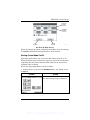
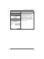
How to Access the Central Station Screen
To Access the “Central Station” screen perform the following:
1. Press the SECURITY button on the “Home” screen. The “Arming” screen is
displayed.
SCREEN
ACTION
2. Press the MORE CHOICES button.
The “More Choices” screen is displayed.
3. Press the SETUP button on the “More
Choices” screen. The “Setup” screen is
displayed.
4. Press the ADVANCED SETUP button.
The Enter Authorized Code:
authorization screen is displayed.
4–3
WWW.DIYALARMFORUM.COM
6270 Installation and Setup Guide
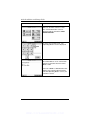
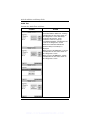
SCREEN
ACTION
5. Enter your 4-digit Installer code. The
“Advanced Setup” menu screen is
displayed.
Note: If the top of the screen is displaying
ECP Error, the ECP address in the 6270
is not valid for the panel that it is
connected to. To change the ECP
address in the 6270 when ECP Error is
being displayed, enter the 6270 default
code of “4140” to advance to the next
screen.
6. Press the Central Station button. The
“Central Station” menu screen is
displayed.
4–4
WWW.DIYALARMFORUM.COM
SECTION 4: Initial Setup
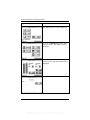
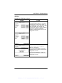
To change the address, perform the following.
SCREEN
ACTION
1. On the “Central Station” screen press
the ECP Address button. A pop-up
window is displayed with options for
selecting the 6270's ECP address.
2. The available ECP addresses are:
1-2 for residential controls or
1-30 for commercial controls
Select the ECP address for this 6270
using the Up/Dn arrows. Press the OK
button to accept the address setting or the
CANCEL button to maintain the original
ECP address. The 6270 goes to the
"Central Station" menu screen.
3. Press the "Back" button three times to
save the new address. The "More
Choices" screen is displayed.
4–5
WWW.DIYALARMFORUM.COM
6270 Installation and Setup Guide
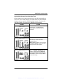
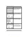
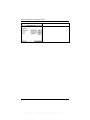
How to Select System Options
The system options allow you to place buttons on the "Home" screen.
The SECURITY and MESSAGES buttons are always displayed and
cannot be removed. A Lighting button can also be added to the
“Home” screen. To avoid confusion to the user, only buttons whose
options are functional in the system should be displayed. To select
the system options, do the following:
SCREEN
ACTION
1. On the “Central Station” screen press
the Options button. A pop-up window is
displayed with an option for selecting
Lighting.
2. Touch the Lighting button to turn the
Lighting option on or off. A checkmark
appears in the button with the Lighting
option is “ON”.
Press the DONE button to accept the
setting. The 6270 returns to the "Central
Station" menu screen.
4–6
WWW.DIYALARMFORUM.COM
SECTION 4: Initial Setup
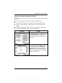
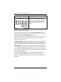
How to Set the NIGHT Setup Button Function
The NIGHT button can be set to arm the system in one of four arming
modes:
x
x
x
x
Away - When selected, arms all zones with entry delay.
Stay - When selected, arms perimeter zones with entry delay.
Instant - When selected, arms perimeter zones without entry
delay.
Maximum - When selected, arms all zones without entry delay.
To set the NIGHT button function, do the following:
SCREEN
ACTION
1. On the “Central Station” screen press
the Night Setup button. A Night Setup:
pop-up window is displayed with options
for selecting Away, Stay, Instant, and
Maximum.
2. Select the arming mode that will be
activated by pressing the NIGHT button
on the "Arming" screen. Press the Ok
button to accept the setting, or press the
Cancel button to cancel your selection. In
either case the 6270 goes to the "Central
Station" menu screen.
4–7
WWW.DIYALARMFORUM.COM
6270 Installation and Setup Guide
SCREEN
ACTION
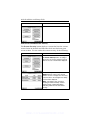
How to View and Edit Screen Security
The Screen Security button displays a screen that lists the various
screen classes in the 6270 and lists what level user has been given
access to them. To view and/or edit screen security, do the following:
SCREEN
ACTION
1. On the “Central Station” screen, press
the Screen Security button. A listing of
the classes of screens and the user level
that has access to them will be displayed.
2. If the listing is correct, depress the
BACK button to return to the “Central
Station” screen. If changes are necessary,
select the line to be changed and a Setup
screen will be displayed.
Note: The Setup screen contains a
heading of Advanced Setup, Central
Station Setup, or Operating Modes
indicating which line was selected for
change.
4–8
WWW.DIYALARMFORUM.COM
SECTION 4: Initial Setup
SCREEN
ACTION
3. Select the level of user who is to have
access to the selected class of screens
and then select the OK button. The
Screen Security screen will be redisplayed listing the change. Depress the
BACK button to return to the “Central
Station” screen.
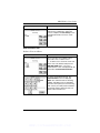
How to View the Panel Configuration
The Panel Config button displays a screen that contains the
configuration of the panel that the 6270 is connected to. To view the
panel configuration, do the following:
SCREEN
ACTION
1. On the “Central Station” screen press
the Panel Config button. A Panel
Configuration screen will be displayed
providing details of your system.
2. Depress the OK button to return to the
“Central Station” screen or if you desire to
clear the configuration from the 6270 and
have it reload the panel configuration into
the 6270 from the panel, depress the
Delete Config? button. After you depress
the Delete Config? button, a confirmation
screen is displayed.
4–9
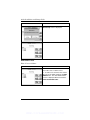
WWW.DIYALARMFORUM.COM
6270 Installation and Setup Guide
SCREEN
ACTION
3. Select OK to delete the configuration
or Cancel to return to the “Panel
Configuration” screen. If you select OK,
the 6270 will be reset and the panel
configuration will be downloaded from the
panel into the 6270. After the reset and
download is complete, the “Home” screen
is displayed.
6270 Setup
Setup allows you to adjust the touch screen contrast and/or adjust the
6270 speaker volume. You may also select the time interval that
must pass prior to the 6270 going into screen saver mode (screen goes
blank). Additionally, you may enter the User Setup screen,
Advanced Setup screen, or Clean Screen (maintenance mode)
from the "Setup" screen by pressing the corresponding button.
Access the "Setup" screen as follows:
1. From the "Home" screen, press the SECURITY button. The "Arming" screen
is displayed.
SCREEN
ACTION
2. Press the MORE CHOICES button.
The "More Choices" screen is displayed.
4–10
WWW.DIYALARMFORUM.COM
SECTION 4: Initial Setup
SCREEN
ACTION
3. Press the SETUP button on the "More
Choices" screen. The "Setup" screen is
displayed.
4. Adjust the touch screen options as
described in the paragraphs that follow.
How to Adjust the Touch Screen Contrast
You may adjust the touch screen contrast as follows:
If…
Then…
you want to increase contrast
press the slide bar above the current
contrast setting.
you want to decrease contrast
press the slide bar below the current
contrast setting.
another adjustment or selection is to
be made
go to the corresponding paragraph in
this section.
no additional adjustment or selection
is to be made
press the BACK button, or
press the HOME button on the 6270
to return to your home screen.
4–11
WWW.DIYALARMFORUM.COM
6270 Installation and Setup Guide
CONTRAST
SLIDE BAR
INDICATOR
6270-006-V0
Touch Screen Contrast Control
How to Adjust the Volume
You may adjust the 6270 speaker volume by pressing your finger on
the touch screen slide bar associated with the "Volume" scale and
doing the following:
If…
Then…
you want to increase volume
press the slide bar above the current
volume setting.
you want to decrease volume
press the slide bar below the current
volume setting.
VOLUME
SLIDE BAR
INDICATOR
6270-007-V0
Volume Control
4–12
WWW.DIYALARMFORUM.COM
SECTION 4: Initial Setup
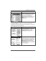
How to Select Screen Saver Activation Time
When the 6270 is not armed and not active, it will automatically go
into screen saver mode (display goes blank) after the selected blank
display time has expired (unless you select “never”). To select the
time after which the screen will go blank, do the following:
SCREEN
ACTION
1. Press the Blank Display After:
"arrow" button. A pull-down menu
displaying the time period options is
displayed.
2. Select the time period option you want
by pressing it. The pop-up window closes
automatically and the selection is
displayed in blue.
Note: Additional options can be viewed
by using the up/down "arrows" to scroll
through the time period options.
3. Press either the "Home" or "Back"
button. A Settings Changed! pop-up
window is displayed asking “Settings
Changed! Remember New Settings?“
Select Yes to save the change or No to
discard the change.
4–13
WWW.DIYALARMFORUM.COM
6270 Installation and Setup Guide
SCREEN
ACTION
When the Update is complete the 6270
goes to the "Home" screen or "More
Choices" screen depending on whether
you pressed the "Home" or "Back" button,
respectively ("More Choices" screen
shown).
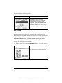
How to Set the Time and Date
You can set the time and date from the Set Time & Date screen.
Pressing the Time and Date bar located at the bottom of each 6270
screen displays the Set Time & Date screen.
When the time is set it will be stored in the 6270 only. The 6270 will
send the time to the control panel every hour. This 1-hour timer
starts on 6270 power-up.
If Adjust for DST (Daylight Savings Time) is selected, the 6270 will
adjust for Daylight Savings time. When selected, the next time the 1hour timer expires, the new value will be sent to the control panel.
IMPORTANT: This means that the 6270 setting will override and
overwrite the control panel time setting. That is, if the control panel
is set to DST and adjusts but the 6270 is not, upon the 1-hour timer
expiration, the control panel will be updated to the current time that
is not adjusted for DST.
From the Set Time & Date screen, adjust either or both the time
and date by pressing the increase or decrease arrow buttons as
necessary until the proper month, day, year, hour, and minute are
displayed.
4–14
WWW.DIYALARMFORUM.COM
SECTION 4: Initial Setup
INCREASE
BUTTON
(TYPICAL)
DECREASE
BUTTON
(TYPICAL)
CANCEL
BUTTON
OK
BUTTON
6270-008-V0
Set Time & Date Screen
When all settings have been completed, select Ok to save the settings
or Cancel to discard the settings that have been entered.
Setting Chime Mode On/Off
Operating modes allows you to turn the 6270 chime mode on or off.
When the chime mode is selected, a request is sent to the alarm panel
requesting that the panel chime the 6270 whenever an entry/exit or
perimeter zone is opened.
Access the "Operating Modes" screen as follows:
1. From the "Home" screen, press the SECURITY button. The "Arming" screen
is displayed.
SCREEN
ACTION
2. Press the MORE CHOICES button.
The "More Choices" screen is displayed.
4–15
WWW.DIYALARMFORUM.COM
6270 Installation and Setup Guide
SCREEN
ACTION
3. Press the OPERATING MODES
button on the "More Choices" screen.
The "User Authorization" screen is
displayed with the instructions "Enter
Authorized Code".
4. Enter your “Installer” code. The
"Operating Modes" screen is displayed.
5. Touch the Chime Mode button to turn
the Chime Mode on or off. A checkmark
appears in the button when the Chime
Mode is “ON”.
Press the “HOME” or “BACK” button after
making your selection. When the 6270
exits the “Operating Modes” screen, your
selection is saved.
4–16
WWW.DIYALARMFORUM.COM
S E C T I O N
5
User Codes
x x x x x x x x x x x x x x x x x x x x x x x x x x x x x x x x
In This Section
♦ Introduction to User Code
Setup
♦ How to Access User Setup
x x x x x x x x x x x x x x x x x x x x x x x x x x x x x x x x
Introduction to User Code Setup
Each user must be assigned a name with a corresponding 4-digit user
code in order to gain access to various features and functions.
Through the 6270, you may program users to access any and all of the
following systems:
x
x
x
Fire/Burglary (Security)
Lighting
Messages
Users for the systems are programmed in a central user setup
location that provides the specific questions for the user pertaining to
each system. You may want these users to be the same, but there are
situations in which you may want a user to have access to one system
(e.g., Messages) without having access to another (e.g., the
Fire/Burglary system).
How to Access User Setup
Access User Setup as follows:
1. From the "Home" screen, press the SECURITY button. The "Arming" screen
is displayed.
5–1
WWW.DIYALARMFORUM.COM
6270 Installation and Setup Guide
SCREEN
ACTION
2. Press the MORE CHOICES button.
The "More Choices" screen is displayed.
3. Press the SETUP button on the "More
Choices" screen. The "Setup" screen is
displayed.
4. Press the USER SETUP button on the
“Setup” screen. The User Setup screen is
displayed.
5–2
WWW.DIYALARMFORUM.COM
SECTION 5: User Codes
How to Add a User
Add a User as follows:
SCREEN
ACTION
1. To add a user, press the ADD USER
button. The "User Authorization" screen
is displayed with the instructions "Enter
Authorized Code".
2. Enter your Authorized code. The “User
Options” screen is displayed.
Note: The authorized code for adding
users is dependent upon the alarm panel
you are interfacing with. Check your alarm
panel Installation and Setup Guide to
determine who can add users.
3. Press the box next to Enter User
Name. The Enter Data keyboard screen
is displayed.
5–3
WWW.DIYALARMFORUM.COM
6270 Installation and Setup Guide
SCREEN
ACTION
4. Type in the user name (6 characters
max.) and press the OK button. The
“User Options” screen is displayed with
Enter User Code… displayed.
5. Touch the box next to Enter User
Code… The "User Authorization" screen
is displayed with the instructions "Enter 4
Digits".
6. Enter the 4-digit code for this user.
The “User Options” screen is displayed
with the user’s name and code displayed.
7. Select the partitions, access level, and
enter a user number for this user.
If assigning this user to wireless key, enter
one of the zone numbers of the keyfob
(the wireless key must be programmed
first before it can be assigned to a user).
5–4
WWW.DIYALARMFORUM.COM
SECTION 5: User Codes
SCREEN
ACTION
8. Press the Save button. The system
will save the configuration. When the
save is complete, the User Setup screen
is displayed with the new user’s name
shown.
How to Delete a User
Delete a User as follows:
SCREEN
ACTION
Three selections are available: add a
user, edit a user, or delete a user.
1. To delete a user, touch the circle next
to the user to be deleted and press the
DELETE USER button. The "User
Authorization" screen is displayed with the
instructions "Enter Authorized Code".
2. Enter your Authorized code. The
Confirm Delete screen is displayed.
Note: The authorized code for deleting,
adding, and editing users is dependent
upon the alarm panel you are interfacing
with. Check your alarm panel Installation
and Setup Guide to determine who can
delete, add, and edit users.
5–5
WWW.DIYALARMFORUM.COM
6270 Installation and Setup Guide
SCREEN
ACTION
3. Press the appropriate button. The
User Setup screen is displayed.
How to Edit a User
Edit a User as follows:
SCREEN
ACTION
Three selections are available: add a
user, edit a user, or delete a user.
1. To edit a user, touch the circle next to
the user to be edited and press the EDIT
USER button. The "User Authorization"
screen is displayed with the instructions
"Enter Authorized Code".
5–6
WWW.DIYALARMFORUM.COM
SECTION 5: User Codes
SCREEN
ACTION
2. Enter your Authorized code. The “User
Options” screen is displayed.
Note: The authorized code for deleting,
adding, and editing users is dependent
upon the alarm panel you are interfacing
with. Check your alarm panel Installation
and Setup Guide to determine who can
delete, add, and edit users.
3. Select whatever options you wish to
select for this user and press the Save
button. The configuration changes are
saved and you are returned to the User
Setup screen.
5–7
WWW.DIYALARMFORUM.COM
6270 Installation and Setup Guide
5–8
WWW.DIYALARMFORUM.COM
S E C T I O N
6
Maintenance
x x x x x x x x x x x x x x x x x x x x x x x x x x x x x x x x
In This Section
♦ About 6270 Maintenance
♦ Routine Care
♦ How to Clean the 6270
x x x x x x x x x x x x x x x x x x x x x x x x x x x x x x x x
About 6270 Maintenance
With the exception of normal cleaning, the 6270 is maintenance free.
How to Clean the 6270
IMPORTANT: Do not use an abrasive cleaning agent or abrasive
cloth when cleaning the 6270 or damage to the touch screen may
occur.
Clean the 6270 as follows:
1. From the "Home" screen, press the SECURITY button. The "Arming" screen
is displayed.
SCREEN
ACTION
2. Press the MORE CHOICES button.
The "More Choices" screen is displayed.
6–1
WWW.DIYALARMFORUM.COM
6270 Installation and Setup Guide
SCREEN
ACTION
3. Press the SETUP button on the "More
Choices" screen. The "Setup" screen is
displayed.
4. Press the CLEAN SCREEN button. A
pop-up window displaying “Touch Screen
will be disabled so that you may wipe
the screen clean. Please use a damp,
soft cloth. DO NOT use any liquids,
sprays, or ammonia-based cleansers.
Press CONTINUE to disable
touchscreen.
When the Continue button is pressed the
“Touch Screen Disabled for => 30
Seconds”. During these 30 seconds the
touch screen should be wiped clean of
fingerprints using a mild soap solution and
a soft cloth. When the counter reaches
zero, the window automatically closes and
the touch screen is active.
Note: Do not spray cleaning agent directly
on the screen, spray it on cloth then wipe
surface area.
6–2
WWW.DIYALARMFORUM.COM
SECTION 6: Maintenance
Routine Care
x
x
x
Treat the components of the security system as you would any
other electrical equipment. Do not slam sensor-protected doors or
windows.
Keep dust from accumulating on the keypad and all protective
sensors, particularly on motion sensors and smoke detectors.
The keypad and sensors should be cleaned carefully with a dry
soft cloth. Do not spray water or any other fluid on the units.
6–3
WWW.DIYALARMFORUM.COM
6270 Installation and Setup Guide
6–4
WWW.DIYALARMFORUM.COM
S E C T I O N
7
Troubleshooting
x x x x x x x x x x x x x x x x x x x x x x x x x x x x x x x x
In This Section
♦ Troubleshooting
♦ Performing Diagnostics
♦ Diagnostics
x x x x x x x x x x x x x x x x x x x x x x x x x x x x x x x x
Troubleshooting
For troubleshooting procedures, refer to the Control Panel
Installation Guide.
Diagnostics
About Diagnostics
A series of diagnostic tests are provided that allows verification of
correct operation of the 6270 and its connections to the security
system. There are a total of three diagnostic tests.
How to Access the Diagnostics
To access diagnostics, do the following:
1. From the "Home" screen, press the SECURITY button. The "Arming" screen
is displayed.
SCREEN
ACTION
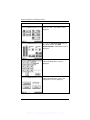
2. From the " Arming" screen press the
MORE CHOICES button. The "More
Choices" screen is displayed.
7–1
WWW.DIYALARMFORUM.COM
6270 Installation and Setup Guide
SCREEN
ACTION
3. Press the SETUP button on the "More
Choices" screen. The "Setup" screen is
displayed.
4. Press the Advanced Setup button on
the "Setup" screen. The Enter
Authorized Code: authorization screen is
displayed.
5. Enter your 4-digit Installer code. The
"Advanced Setup" menu screen is
displayed.
6. Press the Diagnostics button on the
"Advanced Setup" menu screen. The
"Diagnostics" screen is displayed.
7–2
WWW.DIYALARMFORUM.COM
SECTION 7: Troubleshooting
SCREEN
ACTION
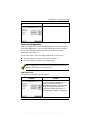
Performing Diagnostics
Select any diagnostic test from the Diagnostics screen by pressing its
associated Test button. All or any individual test may be run when
you access the Diagnostics screen; however, each test must be
performed one at a time.
At any time when a test is not being performed, you can press:
x
x
the back button to return to the previous screen, or
the home button to return to your home page.
Once the Diagnostics screen is exited, subsequent entry to this screen
displays all test options as "Not Performed."
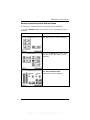
LCD Display Test
Perform the LCD Display Test as follows:
SCREEN
ACTION
1. When you press the Test button
associated with the LCD Display Test, a
pop-up "Confirmation Window" is
displayed in the center of the screen with
an all black background. Within the
Confirmation Window the question "Is
Screen Background Black?" is displayed.
7–3
WWW.DIYALARMFORUM.COM
6270 Installation and Setup Guide
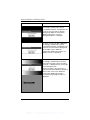
SCREEN
ACTION
2. When you press the Yes or No button
accordingly, automatically a pop-up
"Confirmation Window" is displayed in the
center of the screen with an all white
background. Within the Confirmation
Window the question "Is Screen
Background White?" is displayed.
3. When you press the Yes or No button
accordingly, automatically a pop-up
"Confirmation Window" is displayed in the
center of the screen with the background
in 16 shades of gray. Within the
Confirmation Window the question "16
Shades of Gray?" is displayed.
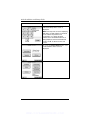
4. When you press the Yes or No button
accordingly, automatically the contrast
test begins from light to dark. "Changing
Contrast.." is displayed in the center of the
screen during this time.
At the conclusion of the contrast test a
Pop-Up Confirmation Window is displayed
in the center of the screen. Within the
Confirmation Window the question
"Contrast Changed (Light to Dark)?" is
displayed.
7–4
WWW.DIYALARMFORUM.COM
SECTION 7: Troubleshooting
SCREEN
ACTION
5. When you press the Yes or No button
accordingly, the "Diagnostics" screen is
displayed with the LCD Display Test
results ("Passed" or "Failed") shown in the
test status column.
Note: If the response was no (the No
button is pressed) to any question of this
test, when the system is returned to the
Diagnostics screen, "Failed" is displayed
in test status column.
7–5
WWW.DIYALARMFORUM.COM
6270 Installation and Setup Guide
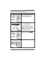
Audio Test
Perform the Audio Test as follows:
SCREEN
ACTION
When you press the Test button
associated with the Audio Test "Testing.."
is displayed in the test status column on
the "Diagnostics" screen while beeps
sound from the speaker. At the
conclusion of the test, a pop-up
"Confirmation Window" is displayed in the
center of the "Diagnostics" screen.
Within the Confirmation Window the
question "Did you hear Beep?" is
displayed.
When you press the Yes button, "Passed"
is displayed in the test status column on
the "Diagnostics" screen.
When you press the No button, "Failed."
is displayed in the test status column on
the "Diagnostics" screen.
7–6
WWW.DIYALARMFORUM.COM
SECTION 7: Troubleshooting
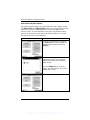
LED Test
Perform the LED Test as follows:
SCREEN
ACTION
1. When you press the Test button
associated with the LED Test, "Testing.."
is displayed in the test status column on
the "Diagnostics" screen while the 3 LEDs
light sequentially, top to bottom (red,
green, amber), 5 times. At the conclusion
of the test, a pop-up "Confirmation
Window" is displayed in the center of the
"Diagnostics" screen.
2. Within the Confirmation Window the
question "Did you see chasing LED
pattern?" is displayed.
If you press the Yes button, "Passed" is
displayed in the test status column on the
"Diagnostics" screen.
If you press the No button, "Failed" is
displayed in the test status column on the
"Diagnostics" screen.
7–7
WWW.DIYALARMFORUM.COM
6270 Installation and Setup Guide
SCREEN
ACTION
7–8
WWW.DIYALARMFORUM.COM
S E C T I O N
8
Specifications
x x x x x x x x x x x x x x x x x x x x x x x x x x x x x x x x
Specifications
MECHANICAL
Dimensions:
Width:
6 ¼ inches
Height:
5 inches
Depth:
1 • inches
ELECTRICAL
Operating Voltage:
Current Drain:
Backlight OFF, Sound OFF
Backlight ON, Sound OFF
Backlight ON, Sound ON
180mA
190mA
210mA
8–1
WWW.DIYALARMFORUM.COM
6270 Installation and Setup Guide
8–2
WWW.DIYALARMFORUM.COM
S E C T I O N
9
Index
x x x x x x x x x x x x x x x x x x x x x x x x x x x x x x x x
About the 6270 ................................................................................................. 1–1
Address Change....................................................................................... 4–2, 4–5
Central Station Screen
Accessing ..................................................................................................... 4–3
Chime Mode ................................................................................................... 4–15
Cleaning ........................................................................................................... 6–1
Compatibility ..................................................................................................... 1–2
Contrast Adjustment ....................................................................................... 4–11
Date Set.......................................................................................................... 4–14
Diagnostics ....................................................................................................... 7–1
Audio Test .................................................................................................... 7–6
LCD Display.................................................................................................. 7–3
LED Test....................................................................................................... 7–7
Performing .................................................................................................... 7–3
ECP Error ......................................................................................................... 1–2
Front Panel Buttons .......................................................................................... 3–2
Front Panel LEDs ............................................................................................. 3–1
Initialization....................................................................................................... 4–2
Maintenance ..................................................................................................... 6–1
Cleaning ....................................................................................................... 6–1
Routine Care................................................................................................. 6–3
Mounting the 6270 ............................................................................................ 2–1
Night Setup....................................................................................................... 4–7
Operating Modes
Chime ......................................................................................................... 4–15
Panel Configuration
Delete ........................................................................................................... 4–9
View.............................................................................................................. 4–9
Power Up.......................................................................................................... 4–2
Routine Care .................................................................................................... 6–3
Screen Saver Activation Adjustment............................................................... 4–13
Screen Security
Edit ............................................................................................................... 4–8
View.............................................................................................................. 4–8
Setup .............................................................................................................. 4–10
Contrast ...................................................................................................... 4–11
Screen Saver Activation Adjustment........................................................... 4–13
Volume ....................................................................................................... 4–12
Specifications ................................................................................................... 8–1
9–1
WWW.DIYALARMFORUM.COM
6270 Installation and Setup Guide
Electrical ....................................................................................................... 8–1
Mechanical.................................................................................................... 8–1
System Features............................................................................................... 1–1
System Options
Selecting....................................................................................................... 4–6
Time and Date
Set .............................................................................................................. 4–14
Time Set ......................................................................................................... 4–14
Troubleshooting................................................................................................ 7–1
Diagnostics ................................................................................................... 7–1
Performing Diagnostics................................................................................. 7–3
User
Adding .......................................................................................................... 5–3
Deleting ........................................................................................................ 5–5
Editing........................................................................................................... 5–6
User Code Setup .............................................................................................. 5–1
Access .......................................................................................................... 5–1
Volume
Adjustment.................................................................................................. 4–12
Wiring the 6270................................................................................................. 2–2
9–2
WWW.DIYALARMFORUM.COM
NOTES
WWW.DIYALARMFORUM.COM
NOTES
WWW.DIYALARMFORUM.COM
NOTES
WWW.DIYALARMFORUM.COM
NOTES
WWW.DIYALARMFORUM.COM
NOTES
WWW.DIYALARMFORUM.COM
NOTES
WWW.DIYALARMFORUM.COM
NOTES
WWW.DIYALARMFORUM.COM
NOTES
WWW.DIYALARMFORUM.COM
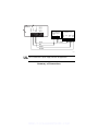
NOT USED
NOT USED
DATA OUT
+12VDC
GND
DATA IN
USER
INTERFACE
+
+
+
+
+
+
BLACK
CONTROL
TERMINAL STRIP
SUPPLEMENTARY
POWER SUPPLY
+
_
AUX
+
_
AUX DATA DATA
IN
OUT
BLACK
RED
GREEN
YELLOW
6270-004-V0
UL Use a Listed Class 2 power supply suited for the application.
Summary of Connections
WWW.DIYALARMFORUM.COM
LIMITED WARRANTY
Honeywell International Inc., acting through its ADEMCO business ("Seller"), 165 Eileen
Way, Syosset, New York 11791, warrants its product(s) to be in conformance with its own
plans and specifications and to be free from defects in materials and workmanship under
normal use and service for 24 months from the date stamp control on the product(s) or, for
product(s) not having an ADEMCO date stamp, for 12 months from date of original
purchase unless the installation instructions or catalog sets forth a shorter period, in which
case the shorter period shall apply. Seller's obligation shall be limited to repairing or
replacing, at its option, free of charge for materials or labor, any product(s) which is proved
not in compliance with Seller's specifications or proves defective in materials or
workmanship under normal use and service. Seller shall have no obligation under this
Limited Warranty or otherwise if the product(s) is altered or improperly repaired or serviced
by anyone other than ADEMCO factory service. For warranty service, return product(s)
transportation prepaid, to ADEMCO Factory Service, 165 Eileen Way, Syosset, New York
11791.
THERE ARE NO WARRANTIES, EXPRESS OR IMPLIED, OF MERCHANTABILITY, OR
FITNESS FOR A PARTICULAR PURPOSE OR OTHERWISE, WHICH EXTEND BEYOND
THE DESCRIPTION ON THE FACE HEREOF. IN NO CASE SHALL SELLER BE LIABLE
TO ANYONE FOR ANY CONSEQUENTIAL OR INCIDENTAL DAMAGES FOR BREACH
OF THIS OR ANY OTHER WARRANTY, EXPRESS OR IMPLIED, OR UPON ANY
OTHER BASIS OF LIABILITY WHATSOEVER, EVEN IF THE LOSS OR DAMAGE IS
CAUSED BY THE SELLER'S OWN NEGLIGENCE OR FAULT.
Seller does not represent that the product(s) it sells may not be compromised or
circumvented; that the product(s) will prevent any personal injury or property loss by
burglary, robbery, fire or otherwise; or that the product(s) will in all cases provide adequate
warning or protection. Customer understands that a properly installed and maintained
alarm system may only reduce the risk of a burglary, robbery, fire, or other events occurring
without providing an alarm, but it is not insurance or a guarantee that such will not occur or
that there will be no personal injury or property loss as a result. CONSEQUENTLY,
SELLER SHALL HAVE NO LIABILITY FOR ANY PERSONAL INJURY, PROPERTY
DAMAGE OR OTHER LOSS BASED ON A CLAIM THAT THE PRODUCT(S) FAILED TO
GIVE WARNING. HOWEVER, IF SELLER IS HELD LIABLE, WHETHER DIRECTLY OR
INDIRECTLY, FOR ANY LOSS OR DAMAGE ARISING UNDER THIS LIMITED
WARRANTY OR OTHERWISE, REGARDLESS OF CAUSE OR ORIGIN, SELLER'S
MAXIMUM LIABILITY SHALL NOT IN ANY CASE EXCEED THE PURCHASE PRICE OF
THE PRODUCT(S), WHICH SHALL BE THE COMPLETE AND EXCLUSIVE REMEDY
AGAINST SELLER.
This warranty replaces any previous warranties and is the only warranty made by Seller on
this product(s). No increase or alteration, written or verbal, of the obligations of this Limited
Warranty is authorized.
165 EILEEN WAY, SYOSSET, NY 11791
Copyright © 2003 Honeywell International Inc.
www.ademco.com
¬.4l
K0977
4/03
WWW.DIYALARMFORUM.COM