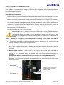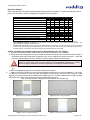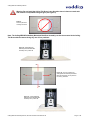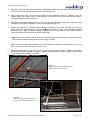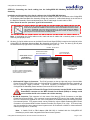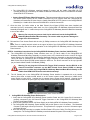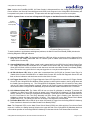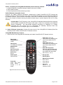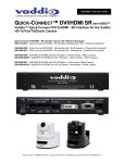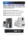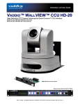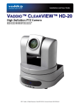
1
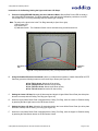
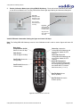
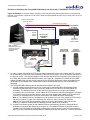
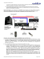
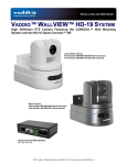
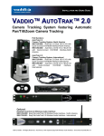
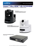
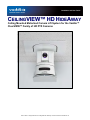
Installation and User Guide CEILINGVIEW™ HD HIDEAWAY Ceiling Mounted Motorized Camera Lift System for the Vaddio™ ClearVIEW™ Family of HD PTZ Cameras ©2011 Vaddio - All Rights Reserved ● CeilingVIEW HD HideAway ● Document Number 342-0289 Rev. B CeilingVIEW HD HideAway Manual Inside Front Cover - Blank CeilingVIEW HD HideAway Manual, Document Number 342-0289 Rev. B Page 2 of 24 CeilingVIEW HD HideAway Manual Vaddio CeilingVIEW HD HideAway Overview: Figure 1: Vaddio CeilingVIEW HD HideAway motorized camera lift system with a *Vaddio ClearVIEW HD-18AW Camera *Camera not included The Vaddio CeilingVIEW HD HideAway is a ceiling mounted motorized camera lift system that provides the ability to quietly lower a Vaddio ClearVIEW HD PTZ camera from the ceiling, retract it back into the ceiling and completely hide the camera. The CeilingVIEW HD HideAway enclosure presents a more aesthetically pleasing solution for camera mounting when compared to exposed wall ceiling mounts. It provides a more secure mount for the camera that helps deter tampering and camera theft and also provides meeting presenters and attendees assurance of their privacy. They can see when the camera is retracted or hidden in the ceiling and when the camera is no longer in use. The CeilingVIEW HD HideAway has been designed to be installed in most suspended ceilings and attached to the building structure. Choose any of Vaddio's WallVIEW HD-20/19/18 Short Range or DVI/HDMI Systems **. The CeilingVIEW CCU Image Controller for CeilingVIEW HD-18 DocCAM can be used with a Vaddio HD-18 or HD-20 Camera for the CeilingVIEW HD HideAway. The CeilingVIEW HD HideAway Power Interface provides power, video and control over Cat. 5 cables from the physical lift system to the head end. The motorized back box assembly, ceiling bridge mounting bracket and ceiling trim ring offer an easy-to-install, high definition lift solution for any presentation room. Overall, the CeilingVIEW HD HideAway is uniquely designed for applications such as classrooms, boardrooms, conference rooms, auditoriums, videoconferencing, training facilities and distance-learning applications in which security, assurance of privacy and aesthetics are room design requirements. **Not compatible with Vaddio WallVIEW CCU versions or ClearVIEW "naked" versions. Intended Use: Before operating the device, please read the entire manual thoroughly. The system was designed, built and tested for use indoors, and with the provided power supply and cabling. The use of a power supply other than the one provided or outdoor operation has not been tested and could damage the device and/or create a potentially unsafe operating condition. Important Safeguards: Read and understand all instructions before using. Do not operate any device if it has been dropped or damaged. In this case, a Vaddio technician must examine the product before operating. To reduce the risk of electric shock, do not immerse in water or other liquids and avoid extremely humid conditions. Use only the power supply provided with the system. Use of any unauthorized power supply will void any and all warranties. Please do not use “pass-thru” type RJ-45 connectors. These pass-thru type connectors do not work well for professional installations and can be the cause of intermittent connections which can result in the RS-232 control line failing and locking up, and/or compromising the HSDS™ signals. For best results please use standard RJ-45 connectors and test all cables for proper pin-outs prior to use and connection to Vaddio product. Save These Instructions: The information contained in this manual will help you install and operate your product. If these instructions are misplaced, Vaddio keeps copies of Specifications, Installation and User Guides and most pertinent product drawings for the Vaddio product line on the Vaddio website. These documents can be downloaded from www.vaddio.com free of charge. CeilingVIEW HD HideAway Manual, Document Number 342-0289 Rev. B Page 3 of 24 CeilingVIEW HD HideAway Manual Unpacking Carefully remove all parts from the packaging and identify the following parts: CeilingVIEW HD HideAway, Part Number 999-2520-000 North America includes: One (1) CeilingVIEW HD HideAway Motorized Back Box Assembly One (1) White Trim Ring Assembly with five (5) white screws (6/32” x 1/2” Phillips flat head screws) One (1) Ceiling Tile Brace One (1) Lower Décor Plate One (1) CeilingVIEW HD HideAway Power Interface (998-2520-002) One (1) PowerRite 24VDC, 2A Power Supply One (1) Power Cord Set for North America One (1) RJ-45 to DB9 EZ Camera Control Adapter (998-1001-232) Installation and User Guide (342-0289) CeilingVIEW HD HideAway, Part Number 999-2520-001 International includes: One (1) CeilingVIEW HD HideAway Motorized Back Box Assembly One (1) White Trim Ring Assembly with five (5) white screws (6/32” x 1/2” Phillips flat head screws) One (1) Ceiling Tile Brace One (1) Lower Décor Plate One (1) CeilingVIEW HD HideAway Power Interface (998-2520-002) One (1) PowerRite 24VDC, 2A Power Supply One (1) Euro Power Cord One (1) UK Power Cord One (1) RJ-45 to DB9 EZ Camera Control Adapter (998-1001-232) Installation and User Guide (342-0289) Figure 2: System Configuration with CeilingVIEW HD HideAway motorized camera lift, CeilingVIEW HD HideAway Power Interface, HD18AW PTZ Camera, Quick-Connect DVI/HDMI SR, ProductionVIEW HD MV with TeleTouch Touch Screen 22” Monitor and Projector. ¾” Conduit Connector 3-LCD Projector Three (3) Cat-5e Cables Up to 100’ (30.4m) CeilingVIEW HD HideAway Motorized Lift System YPbPr Lift Power and Contact Closure Note: A Vaddio ClearVIEW HD-18AW PTZ Camera is hidden inside the CeilingVIEW HD HideAway TeleTouch 22” Touch Screen Monitor Power to Camera, HD Video Returned Camera Control RS-232 RS-232 CeilingVIEW HD HideAway Power Interface Quick-Connect DVI/HDMI-SR DVI-D YPbPr Contact Pair for lift up/down ProductionVIEW HD MV CeilingVIEW HD HideAway Manual, Document Number 342-0289 Rev. B Page 4 of 24 CeilingVIEW HD HideAway Manual STEP BY STEP INSTALLATION INSTRUCTIONS: The CeilingVIEW HD HideAway is a motorized lift system enclosure specifically designed for Vaddio HD Cameras to be installed in a suspended acoustic ceiling tile. Recommended average room ceiling height range is between 8’ and 12’ (2.44m to 3.66m). It can also be used in larger group rooms, lecture halls or auditoriums depending on the system design requirements. Before Starting the Installation: Before starting the installation of the CeilingVIEW HD HideAway, check above the ceiling where you plan to install the motorized camera lift system and make sure the area is clear of obstructions and confirm that there is adequate room for the motorized camera lift system enclosure. Verify that you have proper building structure to attach the required seismic bracing cable and support cables for the CeilingVIEW HD HideAway. All above ceiling work must conform to local building codes and should be performed by qualified personnel. The motorized camera lift system back box and ceiling tile brace allow for superior flexibility and positioning freedom when used with 2’x 2’ and 2’x 4’ ceiling tiles. The motorized camera lift system does not have to be mounted in the center of the tile. The motorized camera lift system back box can be turned to position the camera in four directions in the ceiling tile brace as well (see Figure 10). (Please review all installation instructions prior to starting installation). When terminating the Cat-5e cabling make sure that each cable is individually marked and tested at each end for proper termination with a Cat-5e continuity tester. Important Note: It is very important to set the IR Frequency in the CeilingVIEW HD HideAway to match the IR Frequency of the Vaddio Camera in order to use the Vaddio IR Remote Commander. The Vaddio IR Remote Commander can then be utilized to set the Upper and Lower Lift Stop Settings in the CeilingVIEW HD HideAway and to provide PTZ Control/Power of the Vaddio HD Camera. STEP 1: Matching the IR Frequency of the CeilingVIEW HD HideAway and the Vaddio ClearVIEW HD Camera: A. Remove the CeilingVIEW HD HideAway Motorized Back Box Assembly from the shipping carton and position it vertically on a suitable and safe work surface. B. Remove the nine (9) Phillips screws from the Front Access Panel and remove the panel. Note: There is a safety interlock switch on the upper left side of the CeilingVIEW HD HideAway Back Box Assembly that will not allow operation of the CeilingVIEW HD HideAway with the Front Access Panel removed. C. Matching the IR Frequency: There are three (3) IR frequency settings for all Vaddio ClearVIEW HD Cameras. They are referred to as Camera 1, 2 or 3 on the Vaddio IR Remote Commander. The IR settings are set by dip switch settings on both the Vaddio HD Camera and the CeilingVIEW HD HideAway. Setting the Dip Switches on the Main Printed Circuit Board in the CeilingVIEW HD HideAway: The Main Printed Circuit Board (PCBA) is located on the left inside panel of the CeilingVIEW HD HideAway. The Dip Switches are located on the lower side of the board and faces the Front Access Panel (see Figure 3). Main Printed Circuit Board (PCBA) Figure 3: Location of dip switches on the main printed circuit board assembly (PCBA) Dip Switches 1-6 (top to bottom) CeilingVIEW HD HideAway Manual, Document Number 342-0289 Rev. B Page 5 of 24 CeilingVIEW HD HideAway Manual Dip Switch Settings: Set the dip switches to the desired settings and then apply power to the system. To make any changes, remove power from the system, make the change and re-apply power to the system. Description / Dip Switch 1 2 3 4 5 6 R** R** * * * * CeilingVIEW HD HideAway Camera 2 IR Frequency Setting L** R** * * * * CeilingVIEW HD HideAway Camera 3 IR Frequency Setting R** L** * * * * 6 CeilingVIEW HD HideAway IR Settings: CeilingVIEW HD HideAway Camera 1 IR Frequency Setting Vaddio ClearVIEW HD-20 Camera IR Settings: 1 2 3 4 5 Vaddio ClearVIEW HD-20 IR 1 Setting UP UP UP UP*** * * Vaddio ClearVIEW HD-20 IR 2 Setting UP DN UP UP*** * * Vaddio ClearVIEW HD-20 IR 3 Setting UP UP DN UP*** * * 1 2 3 4 5 6 UP UP UP*** * * * Vaddio ClearVIEW HD-18/HD-19-18/HD-19 Vaddio ClearVIEW HD-18 and HD-19 IR 1 Setting Vaddio ClearVIEW HD-18 and HD-19 IR 2 Setting DN UP UP*** * * * Vaddio ClearVIEW HD-18 and HD-19 IR 3 Setting DN DN UP*** * * * * Position not applicable - currently dip switches marked * are in reserve for future use, please leave UP or R at this time. **CeilingVIEW HD HideAway IR Settings: The dip switches are vertically mounted on the Main Circuit Board (PCBA). The switches are set to the Right or Left (see Figure 3). ***IR OUT OFF: This dip switch is UP when using the Vaddio IR Remote Commander. This switch should be down if IR Forwarding is used or if the Vaddio IR Remote Commander will not be used. Note: If the dip switch is set to DN it will disable the IR receiver in the Vaddio Camera. The Vaddio Camera will not respond to the Vaddio IR Remote Commander. STEP 2: Assembly and Installation Instructions for Suspended Acoustic Tile Ceilings: A. Determine the desired location, distance and centering of the camera for your installation. B. Check above the ceiling where you plan to install the motorized lift system and verify that the area is clear of obstructions and confirm that there is adequate room for the motorized lift system enclosure. Verify that you have proper building structure to attach the required support cables for the enclosure. Warning: Do not install the CeilingVIEW HD HideAway in any suspended acoustic tile ceiling without support cables! The support cables must be properly attached to the CeilingVIEW HD HideAway and to building structure. Verify your installation conforms to all applicable local building codes with local officials! C. Remove the suspended ceiling tile that is to be used to install the CeilingVIEW HD HideAway from the ceiling grid. D. Place the suspended ceiling tile on a suitable and safe work surface. E. Position the Ceiling Tile Brace on the top of the suspended ceiling tile to be used for installation. The Ceiling Tile Brace can be located in most any place (horizontally on the tile) from one end of the ceiling tile to the opposite end; it does not have to be centered in the middle of the tile. However, verify that the Ceiling Trim Ring will fit within the surface of the tile and not cover the suspended ceiling grid. Note: The Ceiling Tile Brace is designed to lie across the tile in a 2 ft. direction only. Figure 4: Ceiling Tile Brace on ceiling tile Figure 6: Cut-out of ceiling tile opening CeilingVIEW HD HideAway Manual, Document Number 342-0289 Rev. B Figure 5: Outline of ceiling tile opening Figure 7: Ceiling Tile Brace with opening Page 6 of 24 CeilingVIEW HD HideAway Manual Warning: Do not install the Ceiling Tile Brace in any direction where it does not reach each side of the 2 ft. suspended ceiling tile grid (see Figure 8). Figure 8: Incorrect placement of Ceiling Tile Brace Note: The CeilingVIEW HD HideAway Motorized Back Box Assembly can also be mounted in the Ceiling Tile Brace with the camera facing any one of four positions: Figure 9: CeilingVIEW HD HideAway Motorized Back Box Assembly set in position #1 #1 #4 #2 Figure 10: The four positions the CeilingVIEW HD HideAway Motorized Back Box Assembly can be placed on the Ceiling Tile Brace #3 Figure 11: CeilingVIEW HD HideAway Motorized Back Box Assembly set in position #2 CeilingVIEW HD HideAway Manual, Document Number 342-0289 Rev. B Page 7 of 24 CeilingVIEW HD HideAway Manual F. When the Ceiling Tile Brace has been placed in the desired position, trace the outline of the center opening of the Ceiling Tile Brace on the suspended ceiling tile (see Figure 5). G. Using a sharp utility knife, score the marked outline on the suspended ceiling tile. Carefully cut out the marked outline. Note: When cutting out the opening, cut out each of the four (4) corners of the outline to make the opening square (see Figure 6). H. Re-install the suspended ceiling tile that has the cutout opening back into the ceiling grid. Place the Ceiling Tile Brace on top of the tile and align it to the cutout opening (see Figure 7). I. Provide and install four (4) individual support cables for connection to the Ceiling Tile Brace (see Figure 12) Attach each of the support cables for the CeilingVIEW HD HideAway System to the appropriate building structure support. Note: The photo examples (see Figures 12 and 13) show the use of cable clamps to secure the cable to the ceiling structure and the turnbuckles. Note: Use of a turnbuckle for each of the four (4) individual support cables is highly recommended and will make it easier to adjust the cable tension on the Ceiling Tile Brace. J. Attach the four-individual support cables to the Ceiling Tile Brace utilizing the provided holes in the four (4) outer corners of the Ceiling Tile Brace (see Figure 13). K. Install the turnbuckles on each of the four (4) corners of the Ceiling Tile Brace. Tighten each cable to provide equal tension to support the Ceiling Tile Brace (without lifting the Ceiling Tile Brace off of the ceiling tile) and secure each of the four (4) cables. Figure 12: Support cable attached to building structure to support the weight of the enclosure Figure 13: Outline of Ceiling Tile Brace opening with four (4) turnbuckles attached to the brace CeilingVIEW HD HideAway Manual, Document Number 342-0289 Rev. B Page 8 of 24 CeilingVIEW HD HideAway Manual L. Carefully lower and place the CeilingVIEW HD HideAway Motorized Back Box Assembly into the Ceiling Tile Brace opening. Figure 14: CeilingVIEW HD HideAway Motorized Back Box Assembly inserted into the Ceiling Tile Brace M. Check and verify that each of the four (4) individual support cables are all equal in tension and that the weight of the CeilingVIEW HD HideAway is supported mainly by the cables and not by the suspended ceiling tile. This can be verified by looking carefully at the ceiling tile below the ceiling and checking for signs of curving or bowing of the ceiling tile (compare to other suspended ceiling tiles near your installation area). If it appears that the ceiling tile is bowing, increase the tension in equal minimal amounts for each of the fourindividual support cables and check to see if the bowing decreases. It is important to have some weight on the tile (approximately 25-50% of the total weight). Do not adjust the tension so that any corner or the entire Ceiling Tile Brace is completely off the suspended ceiling tile. N. Carefully set the Vaddio CeilingVIEW HD PTZ Camera on the Camera Lift Platform inside the CeilingVIEW HD HideAway Motorized Back Box Assembly. Connect the Gray RJ 45 jack to the RS-232 Control IN port on the Vaddio CeilingVIEW HD PTZ Camera. Connect the Black RJ-45 jack to the EZ-Power/Video port on the Vaddio CeilingVIEW HD PTZ Camera. Note: Do not connect the Black RJ-45 EZ Power/Video Cable into the RS-232 Control IN Port or damage may occur to the Vaddio CeilingVIEW HD PTZ Camera. O. Align the Vaddio CeilingVIEW HD PTZ Camera with the mounting holes in the Camera Lift Platform and insert the camera mounting screws. Check alignment of the Vaddio CeilingVIEW HD PTZ Camera to the mounting bracket and tighten the camera mounting screws (see Figures 15 and 16). CeilingVIEW HD HideAway Manual, Document Number 342-0289 Rev. B Page 9 of 24 CeilingVIEW HD HideAway Manual P. Attach the Lower Décor Plate to the bottom of the Camera Platform with three (3) white pan head screws. Camera mounting screw locations IR Sensor Circuit Board Cable Figure 15: Vaddio ClearVIEW HD-18 PTZ HD Camera mounted on the Camera Lift Platform Q. Figure 16: View of Camera Lift Platform from below ceiling with IR Sensor Circuit Board Cable exposed Attachment of the Ceiling Trim Ring Assembly to the CeilingVIEW HD HideAway Motorized Back Box Assembly: I. The IR Sensor Circuit Board is connected by a four (4) conductor Phoenix Connector on a cable that is located on the bottom rear of the CeilingVIEW HD HideAway Motorized Back Box Assembly. Attach the four (4) conductor Phoenix Connector to the IR Sensor Circuit Board and carefully feed the excess cable back into the CeilingVIEW HD HideAway Motorized Back Box Assembly. II. Align and attach the Ceiling Trim Ring Assembly to the CeilingVIEW HD HideAway Motorized Back Box Assembly with five (5) white countersunk screws. Important Note: As the Ceiling Trim Ring Assembly is attached to the CeilingVIEW HD HideAway back box Assembly, do not let the Ceiling Trim Ring Assembly hang by the IR Sensor Cable or put tension on the IR Sensor Cable, damage may occur! Provide continuous support of the Ceiling Trim Ring Assembly while installing the five (5) countersunk screws until all five (5) screws are installed and tightened firmly and evenly to prevent warping of the Ceiling Trim Ring Assembly. Figure 17: View of Ceiling Trim Ring Assembly and Lower Décor Plate attached to the CeilingVIEW HD HideAway Motorized Back Box Assembly CeilingVIEW HD HideAway Manual, Document Number 342-0289 Rev. B Page 10 of 24 CeilingVIEW HD HideAway Manual STEP #3: Connecting the Cat-5e cabling into the CeilingVIEW HD HideAway Motorized Back Box Assembly. Installation and Connection of the Cat-5e cabling to the CeilingVIEW HD HideAway: A. Insert the individually marked and tested three (3) Cat-5e cables necessary for connection to the CeilingVIEW HD HideAway Motorized Back Box Assembly through the provided ¾” conduit feed-through in the left side of the Back Box Assembly. Recommended maximum Cat-5e cable length for each cable is 100ft. Note: Please do not use “pass-thru” type RJ-45 connectors! Please do not use “pass-thru” type RJ-45 connectors. These pass-thru type connectors do not work well for professional installations and can be the cause of intermittent connections which can result in the RS-232 control line failing and locking up, and/or compromising the HSDS™ signals. For best results please use standard RJ-45 connectors and test all cables for proper pin-outs prior to use and connection to Vaddio product. Note: If terminating the Cat-5e cables on-site, mark and test all cables with a continuity tester to confirm continuity and proper pin-outs. B. All three (3) Cat-5e cables connect to the Main Printed Circuit Board (PCBA) located on the inside left of the CeilingVIEW HD HideAway Motorized Back Box Assembly (see Figure 3). Note: The three (3) RJ-45 jacks are located at the top right corner of the Main Circuit Board (see Figure 18). RS-232 - RJ-45 Jack 2 Camera Power /Video Input - RJ-45 Jack 3 Lift Power/Trigger Input - RJ-45 Jack 1 Vaddio Quick-Connect DVI/HDMI SR or Quick-Connect SR CeilingVIEW HD HideAway Power Interface Connect to Vaddio ProductionVIEW Control Consoles, Control Systems or Video Conference Codecs Figure 18: Location of RJ-45 jacks on the Main Circuit Board/Security Cover Labeling Lift Power/Lift Trigger In Connector: The RJ-45 connector on the top right side (as you face the Main Printed Circuit Board (PCBA) inside the CeilingVIEW HD HideAway Motorized Back Box Assembly) is the Lift Power/Lift Trigger Connector. This RJ-45 connector is configured for connection to the CeilingVIEW HD HideAway Power Interface Power and Lift RJ-45 Connector. Do not plug the Lift Power/Lift Trigger RJ-45 connector into the RS-232 or the Camera Power/Video connector on the Main Printed Circuit Board (PCBA) or damage could occur to either the lift or the camera and void the warranty. RS-232 IN Connector: This connector is in the center of the three (3) RJ-45 Connectors on the Main Printed Circuit Board (PCBA). This connector is used to provide PTZ control of the Vaddio ClearVIEW HD PTZ Camera that is installed for use in the CeilingVIEW HD HideAway motorized camera lift system from external devices. PTZ camera control can be provided by various Vaddio ProductionVIEW Control Consoles or a ProductionVIEW Precision Camera Controller (see Figure 27 for a list). PTZ control may also be controlled by other external control systems such as Crestron® or AMX® or videoconference codecs (see Figures 27, 28 and 29). Note: A Vaddio RJ-45 to DB-9 adapter (998-1001-232) is included with the CeilingVIEW HD HideAway to provide easier integration with external control systems. CeilingVIEW HD HideAway Manual, Document Number 342-0289 Rev. B Page 11 of 24 CeilingVIEW HD HideAway Manual The CeilingVIEW HD HideAway motorized camera lift system and the Vaddio ClearVIEW HD PTZ Camera can also be controlled by the Vaddio IR Remote Commander, which is included with all Vaddio ClearVIEW HD PTZ Cameras. Camera Power/EZ Power Video IN Connector: This connector provides a two-way function: It receives the camera power required for the Vaddio ClearVIEW HD PTZ Camera inside the CeilingVIEW HD HideAway and sends the HD video from the Vaddio ClearVIEW HD PTZ Camera in the CeilingVIEW HD HideAway to a Vaddio Quick-Connect DVI/HDMI SR or a Quick-Connect SR. C. Once the three (3) Cat-5e cables to the Main Printed Circuit Board (PCBA) have been installed and connected, pull any unnecessary cable slack out of the CeilingVIEW HD HideAway Motorized Back Box Assembly and tighten the ¾” conduit clamp on the CeilingVIEW HD HideAway Motorized Back Box Assembly to secure the cables. Warning: Do not push any excess slack Cat-5e cable back into the CeilingVIEW HD HideAway Motorized Back Box Assembly. The excess cable may become damaged or caught in the lift mechanism! D. Re-install the Front Access Panel with the nine (9) Phillips screws on the CeilingVIEW HD HideAway back box. Note: There is a safety interlock switch on the upper left side of the CeilingVIEW HD HideAway Motorized Back Box Assembly that will not allow operation of the CeilingVIEW HD HideAway with the Front Access Panel removed. STEP 4: Installation Instructions for the CeilingVIEW HD HideAway Power Interface (998-2520-002): A. The CeilingVIEW HD HideAway Power Interface uses one (1) Cat-5e cable to the CeilingVIEW HD HideAway Motorized Back Box Assembly to provide power to the motorized lift and to send a lift trigger control signal to the CeilingVIEW HD HideAway Motorized Back Box Assembly to raise and lower the lift. This RJ-45 cable is connected to the Lift Power/Lift Trigger Connector on the CeilingVIEW HD HideAway Main Printed Circuit Board (PCBA) located inside the back box. The RJ-45 connector on the top right side (as you face the Main Printed Circuit Board (PCBA)). Warning: Do not plug the Lift Power/Lift Trigger RJ-45 connector into the RS-232 or the Camera Power/Video connector on the Main Printed Circuit Board (PCBA) or damage could occur to either the CeilingVIEW HD HideAway Motorized Back Box Assembly or the Vaddio ClearVIEW HD PTZ Camera and void the warranty! B. The Lift Contact pair on the CeilingVIEW HD HideAway Power Interface is operated with a dry contact closure (from either a simple manual switch or an A/V control system contact closure) to initiate the lift control signal to lower the lift. Latching the dry contact closure keeps the lift lowered. Opening the lift contact closure raises the lift (see Figure 19). Note: RS-232 lift commands will override the contact closure. Figure 19: CeilingVIEW HD HideAway Power Interface 998-2520-002 C. CeilingVIEW HD HideAway Power On Sequence: 1. Verify that the CeilingVIEW HD HideAway Power Interface Power and Lift Contact RJ-45 connector is properly connected to the Lift Power/Lift Trigger Connector on the CeilingVIEW HD HideAway Main Printed Circuit Board (PCBA). 2. Connect the PowerRite 24VDC, 2A Power Supply to the CeilingVIEW HD HideAway Power Interface. 3. The CeilingVIEW HD HideAway Power Interface will provide power to the Lift Actuator. The Motorized Camera Lift will begin a Boot-Up Procedure. This procedure is a program to set the Lift Actuator upper and lower lift limits. 4. Once the Boot-Up Procedure is complete, the Blue Power LED on the Ceiling Trim Ring will turn on to a steady blue. The CeilingVIEW HD HideAway motorized camera lift system is then ready for use. CeilingVIEW HD HideAway Manual, Document Number 342-0289 Rev. B Page 12 of 24 CeilingVIEW HD HideAway Manual Note: Anytime the PowerRite 24VDC, 2A Power Supply is disconnected from the CeilingVIEW HD HideAway Power Interface, the Boot-Up Procedure/Upper and Lower Limits Program in the CeilingVIEW HD HideAway will be repeated once power is reconnected. This procedure will take approximately one minute to complete. STEP 5: System Power on and use of Diagnostic LED Lights on the Main Printed Circuit Board (PCBA) The Main Printed Circuit Board (PCBA) Diagnostic LED’s on the Main Printed Circuit Board (PCBA) LED’s 1-6 (Top to Bottom) Figure 20: Location of Diagnostic LED’s on the Main Printed Circuit Board (PCBA) Figure 21: Diagnostic LED’s Label on the Main Printed Circuit Board (PCBA) Security Cover. To assist installers to troubleshoot and diagnose problems, the Main Printed Circuit Board (PCBA) includes the following Diagnostic LED light indicators: 1) Camera Power Blue LED: The Camera Power Blue LED light will be on whenever there is Camera Power being sent to the Vaddio ClearVIEW HD PTZ Camera (from a Vaddio Quick-Connect DVI/HDMI SR or a Vaddio Quick-Connect SR). 2) Camera RS232 Green LED: When a serial code is transmitted from the RS-232 to the Camera Control Port of a Vaddio Quick-Connect DVI/HDMI SR or a Vaddio Quick-Connect SR, the Camera RS-232 Diagnostic Green LED will flash or blink to indicate a code has been received at the Main Printed Circuit Board (PCBA). Note: This can be a very quick blink or it may not trigger due to a very short code sequence. 3) QC RS-232 Green LED: When a serial code is transmitted from the RS-232 to Camera Control Port of a Vaddio Quick-Connect DVI/HDMI SR or a Vaddio Quick-Connect SR, the RS-232 Diagnostic Green LED will flash or blink to indicate a code has been sent from the Quick-Connect. 4) Lift Trigger Green LED: The Lift Trigger Diagnostic Green LED light will be on when the Lift Trigger Contact Closure on the CeilingVIEW HD HideAway Power Interface is closed (which results in the lift going down and the Vaddio Camera powering on). The CeilingVIEW HD Hideaway Camera Lift will continue to stay down until the Lift Trigger Contact Closure is opened. When the Lift Trigger Contact is opened, the Camera Lift will retract back into the CeilingVIEW HD HideAway and power down the Vaddio ClearVIEW HD PTZ Camera. 5) Lift Calibrate Yellow LED: The Yellow LED will turn on when lift calibration is activated. To activate Lift Calibration, the Blue Power LED must be on steady in the CeilingVIEW HD HideAway Trim Ring Assembly and the Camera Lift is inside the CeilingVIEW HD HideAway. Press and hold the Calibration push button on the IR Circuit Board in the Trim Ring Assembly until Blue Power light is flashing (see Instructions for Calibrating: Setting the Upper and Lower Lift Stops). The Yellow LED on the Main Printed Circuit Board (PCBA) will turn on. The Yellow LED will turn off when the Lift Calibration is de-activated 6) Lift Power Blue LED: A Blue LED will be on when Lift Power/Lift Trigger from the CeilingVIEW HD HideAway Power Interface is detected in the Main Printed Circuit Board (PCBA). Note: The Diagnostic LED’s on the Main Printed Circuit Board (PCBA) are visible with the Front Access Panel removed. However, the Safety Interlock Switch on the upper left side of the CeilingVIEW HD HideAway back box will not allow operation of the CeilingVIEW HD HideAway Lift Actuator with the Front Access Panel removed. CeilingVIEW HD HideAway Manual, Document Number 342-0289 Rev. B Page 13 of 24 CeilingVIEW HD HideAway Manual STEP 6: Controlling the CeilingVIEW HD HideAway with the following methods: 1) Vaddio IR Remote Commander (Setting the Upper and Lower Lift Stops) 2) Other Vaddio Products 3) Control Systems and Videoconferencing Codecs Vaddio IR Remote Commander Control: Overview: The Vaddio IR Remote Commander, included with all Vaddio ClearVIEW HD PTZ Cameras and packages, provides for simple IR remote control of the CeilingVIEW HD HideAway and the Vaddio ClearVIEW HD PTZ Camera functions. The IR Remote Commander is also used to calibrate and set the upper and lower lift stops on the Camera Lift Bracket ensuring the platform bracket stops in precise alignment with the Trim Ring Assembly. Important Note: The IR Frequency of the CeilingVIEW HD HideAway Motorized Back Box Assembly and the Vaddio ClearVIEW HD PTZ Camera must match in order to be controlled by the Vaddio IR Remote Commander! See Step-by-Step Assembly Instructions for Installation of a Vaddio ClearVIEW HD PTZ Camera into the CeilingVIEW HD HideAway Motorized Back Box Assembly/STEP #2: N through O (Pg 9) for more information. 1) Vaddio IR Remote Commander: Provides IR remote control of the CeilingVIEW HD HideAway Back Box Assembly and the Vaddio ClearVIEW HD PTZ Camera functions. CeilingVIEW HD HideAway Functions: Power On-Off for the CeilingVIEW HD HideAway and Vaddio ClearVIEW HD PTZ Camera functions Back Light Compensation: On/Off Data Screen: For OSD where available Standard Pan: Direction Pan/Tilt Controls: Burgundy buttons Auto Focus: On-Off Zoom Speed: Slow and Fast Power On: Lowers the CeilingVIEW HD HideAway and turns on the Vaddio HD PTZ Camera. Power Off: Raises the CeilingVIEW HD HideAway and turns off the Vaddio HD PTZ Camera. Select IR Frequencies: Select the same IR Setting that the CeilingVIEW HD HideAway and Vaddio HD Camera have been set to (1, 2 or 3). Reverse Pan Pan/Tilt Reset Manual Focus Control: Near and Far Preset Set: Press and hold, touch Preset 1 through 6 to set preset Preset Erase 6-Presets: Stored in the camera for recall Figure 22: Vaddio IR Remote Commander CeilingVIEW HD HideAway Manual, Document Number 342-0289 Rev. B Page 14 of 24 CeilingVIEW HD HideAway Manual Instructions for Calibrating; Setting the Upper and Lower Lift Stops: A. Place the CeilingVIEW HD HideAway into the Calibration Mode: With the Blue Power LED on steady in the CeilingVIEW HD HideAway Trim Ring Assembly, press and hold the Calibration push button on the IR Circuit Board in the Trim Ring Assembly until Blue Power light is flashing. Note: The order of the three holes in the Trim Ring Assembly is (from left to right): 1) Blue Power LED, 2) IR Sensor and 3) Calibration Switch. The Calibration Switch can be activated using a small screw driver. Calibration Switch Blue Power LED Figure 23: CeilingVIEW HD HideAway Ceiling Trim Ring/Calibration Switch Location B. Using the Vaddio IR Remote Commander (which is included with all models of Vaddio ClearVIEW HD PTZ Cameras), press the following buttons to move the lift Up or Down (see Figure 26): ▲ Pan-Tilt Up Arrow: Moves the lift up quickly ► Pan-Tilt Right Arrow: Moves the lift up slowly ▼ Pan-Tilt Down Arrow: Moves the lift down quickly ◄ Pan-Tilt Left Arrow: Moves the lift down slowly C. Setting the Lower Lift Stop: Move the lift downward and align the Upper White Décor Plate (the white plate above the camera) with the Ceiling Trim Ring (see Figure 24). D. When the Upper White Décor Plate is aligned with the Ceiling Trim Ring, save the Lower Lift Position setting by pressing the Back Light button on the IR Remote Control. E. Setting the Upper Lift Stop: Move the lift upward and align the Lower White Décor Plate (the white plate below the camera) with the Ceiling Trim Ring (see Figure 25). F. When the Lower White Décor Plate is aligned with the Ceiling Trim Ring, save the Upper Lift Position setting by pressing the Data Screen button on the IR Remote Control. CeilingVIEW HD HideAway Manual, Document Number 342-0289 Rev. B Page 15 of 24 CeilingVIEW HD HideAway Manual G. End the Calibration Mode in the CeilingVIEW HD HideAway: Press and hold the Calibration push button on the IR Circuit Board in the Trim Ring until the Blue Power light stops flashing and becomes steady blue. Figure 24: CeilingVIEW HD HideAway Lower Lift-Stop Position Upper Lift-Stop Position Align the upper décor plate to the Trim Ring Figure 25: CeilingVIEW HD HideAway Upper Lift-Stop Position Lower Lift-Stop Position Align the lower decor plate to the Trim Ring Vaddio IR Remote Commander: Setting the Upper and Lower Lift Stops Note: The CeilingVIEW HD HideAway must be in the Calibration mode in order to set the Upper and Lower Lift Stops. Back Light Compensation On/Off: Sets the Lower Lift Stop Power On: Lowers the CeilingVIEW HD HideAway and turns on the Vaddio HD PTZ Camera. Power Off: Raises the CeilingVIEW HD HideAway and turns off the Vaddio HD PTZ Camera. Select IR Frequencies: Select the same IR Setting that the CeilingVIEW HD HideAway and Vaddio HD PTZ Camera have been set to (1, 2 or 3). Data Screen: Sets the Upper Lift Stop Pan/Tilt Up: Moves the lift up quickly Pan/Tilt Left: Moves the lift down slowly Pan/Tilt Right: Moves the lift up slowly Pan/Tilt Down: Moves the lift down quickly Figure 26: Vaddio IR Remote Commander CeilingVIEW HD HideAway Manual, Document Number 342-0289 Rev. B Page 16 of 24 CeilingVIEW HD HideAway Manual Control of the CeilingVIEW HD HideAway with other Vaddio Products: The CeilingVIEW HD HideAway is virtually transparent between the Vaddio Camera Control Consoles and Automated Content Presentation Systems and the Vaddio ClearVIEW HD PTZ Cameras. A. The CeilingVIEW HD HideAway has been programmed to power on and off when it receives the power on or off command via RS-232 from the Vaddio Camera Control Consoles and Automated Content Presentation Systems. When the Camera Control Consoles or the Automated Content Presentation Systems Master Power Button is turned on, the Power On command is sent via RS-232 to the CeilingVIEW HD HideAway. It will respond by lowering the camera lift and powering on the Vaddio ClearVIEW HD PTZ Camera. When it senses the Power Off RS-232 command, it will respond by raising the camera lift and powering off the Vaddio ClearVIEW HD PTZ Camera (see Figure 27). B. The ProductionVIEW Camera Control Consoles also provide PTZ control of the Vaddio ClearVIEW HD PTZ Cameras and recall 12 preset PTZ locations, as well as auto/manual focus, auto/manual iris, back light compensation and automatic white balance. C. The Automated Content Presentation Systems (AutoPresenter and ControlVIEW XHD) provide recall of up to 72 preset PTZ locations and when combined with a ProductionVIEW Precision Camera Controller will provide PTZ control of the Vaddio ClearVIEW HD PTZ Cameras auto/manual focus, auto/manual iris, back light compensation and automatic white balance. Figure 27: System Configuration with CeilingVIEW HD HideAway Motorized Lift, CeilingVIEW HD HideAway Power Interface, HD-18W PTZ Camera, Quick-Connect DVI/HDMI SR and ProductionVIEW HD MV Three (3) Cat-5e Cables Up to 100’ (30.4m) Lift Power and Contact Closure Power to Camera, HD Video Returned ¾” Conduit Connector CeilingVIEW HD HideAway Motorized Lift System Camera Control RS-232 Quick-Connect DVI/HDMI-SR CeilingVIEW HD HideAway Power Interface RS-232 ProductionVIEW HD MV List of compatible Vaddio Camera Control Consoles and Automated Content Presentation Systems for control of the CeilingVIEW HD HideAway: ProductionVIEW Camera Control Consoles: ProductionVIEW HD-SDI MV ProductionVIEW HD-SDI ProductionVIEW HD-MV ProductionVIEW HD ProductionVIEW Precision Camera Control ProductionVIEW Super Joystick Automated Content Presentation Systems with Camera Control AutoPresenter ControlVIEW XHD CeilingVIEW HD HideAway Manual, Document Number 342-0289 Rev. B Page 17 of 24 CeilingVIEW HD HideAway Manual Examples of Integrating the CeilingVIEW HD HideAway with Polycom® or TANDBERG (Cisco®) Codecs: Figure 28; Example 1: Polycom Codec: Integration of the CeilingVIEW HD HideAway Motorized Lift, CeilingVIEW HD HideAway Power Interface, Vaddio HD-19 PTZ Camera, Quick-Connect DVI/HDMI SR and a Polycom Codec with Polycom IR Remote Control. Three (3) Cat-5e Cables Up to 100’ (30.4m) Lift Power and Lift Contact ¾” Conduit Connector CeilingVIEW HD HideAway Motorized Lift System CeilingVIEW HD HideAway Power Interface Power to Camera, HD Video Returned Camera Control RS-232 Note: A Vaddio ClearVIEW HD-19 PTZ Camera is inside the CeilingVIEW HD HideAway Quick-Connect DVI/HDMI-SR Interface Lift Contact: Open-Lift Up Closed-Lift Down YPbPr IR/RS-232 Polycom HDX8000 Series IR Remote Control Polycom HDX-8000 Series Codec Polycom Breakout Cable (PN 235-21-001) Vaddio IR Commander Remote Control Vaddio RJ-45 to DB9 Series Adapter (PN 998-1006-232) YPbPr To add the Vaddio ClearVIEW HD PTZ Camera video image and IR control of the Vaddio HD PTZ Camera, it will be necessary to connect a Polycom Breakout Cable (PN 235-21-001) to one of the camera input ports on the Polycom Codec. The Polycom Breakout Cable provides RS-232/IR and component video connectivity to the Vaddio Quick Connect DVI/HDMI SR Interface (see Figure 28). Installation of a Vaddio RJ-45 to DB9 Adapter (PN 998-1006-232) will provide connectivity of the Polycom IR Remote Control commands (Power on/off and PTZ commands) to the Vaddio Quick-Connect DVI/HDMI-SR and on to the CeilingVIEW HD HideAway. The CeilingVIEW HD HideAway can be activated and controlled in two ways: 1) Provide a latched contact closure to the Lift Contact pair on the CeilingVIEW HD HideAway Power Interface (PN 998-2520-002) in order to lower the Vaddio HD PTZ Camera in the CeilingVIEW HD HideAway. The latched closure can be provided by a control system or a simple manual switch connected to the Lift Contact pair. As the Vaddio HD PTZ Camera is lowered by latching the Lift Contact, it will power up and go to its home position. Once the lift has stopped, the Vaddio HD PTZ Camera will receive PTZ commands from the Polycom IR Remote or the Vaddio IR Remote Commander. Note 1: The Vaddio IR Remote Commander must be pointed to the front of the Vaddio HD PTZ Camera (IR receiver location) in order to be received by the camera in order to control PTZ functions. Note 2: The Polycom IR Remote must be pointed at the front of the Polycom Codec (IR Receiver location) to control the CeilingVIEW HD HideAway and the Vaddio HD PTZ Camera. 2) Use the Power Button (green) on the Vaddio IR Remote Commander to power the CeilingVIEW HD HideAway on and lower the camera lift (see Figure 22). The Vaddio IR Remote Commander must be pointed to the CeilingVIEW HD HideAway (in the direction of the IR Sensor in the Trim Plate Assembly (see Figure 23) to activate the CeilingVIEW HD HideAway and lower the camera lift. Once the camera lift CeilingVIEW HD HideAway Manual, Document Number 342-0289 Rev. B Page 18 of 24 CeilingVIEW HD HideAway Manual is lowered, the Vaddio IR Remote Commander must be pointed to the front of the Vaddio HD Camera in order to be received by the camera to control PTZ functions. 3) If IR Forwarding has been connected, you may need to point the Polycom Remote at the camera to provide codec control and PTZ control. However, the Vaddio Remote Control will be ignored including power on-off commands for lift operation. Figure 29; Example 2: Cisco TelePresence (TANDBERG) Codec integration of the CeilingVIEW HD HideAway Motorized Lift, CeilingVIEW HD HideAway Power Interface, Vaddio ClearVIEW HD-20 PTZ Camera, QuickConnect DVI/HDMI SR and a Cisco TelePresence (TANDBERG) Codec with IR Remote Control. Three (3) Cat-5e Cables Up to 100’ (30.4m) Lift Power and Lift Contact ¾” Conduit Connector CeilingVIEW HD HideAway Motorized Lift System Note: A Vaddio ClearVIEW HD-20 PTZ Camera is hidden inside the CeilingVIEW HD HideAway. Vaddio IR Remote Commander CeilingVIEW HD HideAway Power Interface Power to Camera, HD Video Returned Camera Control RS-232 Quick-Connect DVI/HDMI-SR Interface IR/RS-232 IR/RS-232 Cisco TelePresence System (TANDBERG) Codec C60 DVI-D Lift Contact: Open-Lift Up Closed-Lift Down Vaddio RJ-45 to DB9 Series Adapter (PN 998-1002-232) Cisco TelePresence (TANDBERG) IR Remote Control Example 2: Cisco TelePresence System (TANDBERG) Codec with IR Receiver: A. To add the Vaddio HD PTZ Camera video image and IR control of the Vaddio HD PTZ Camera, it will be necessary to connect a Vaddio RJ-45 to DB9 Adapter (PN 998-1002-232) to a COM port on the Cisco TelePresence (TANDBERG) Codec. This will provide connectivity of the IR Remote Control commands (Power-on-off and PTZ commands) to the Vaddio Quick-Connect DVI/HDMI-SR and CeilingVIEW HD HideAway (see Figure 29). B. The CeilingVIEW HD HideAway can be activated and controlled in two ways: 1) Provide a latched contact closure to the Lift Contact pair on the CeilingVIEW HD HideAway Power Interface (PN 998-2520-002) in order to lower the Vaddio HD PTZ Camera in the CeilingVIEW HD HideAway. The latched closure can be provided by a control system or a simple manual switch connected to the Lift Contact pair. As the Vaddio HD Camera is lowered by latching the Lift Contact, it will power up and go to its home position. Once the lift has stopped, the Vaddio HD PTZ Camera will receive PTZ commands from the Cisco TANDBERG IR Remote or the Vaddio IR Remote Commander. Note 1: The Vaddio IR Remote Commander must be pointed to the front of the Vaddio HD PTZ Camera (IR Receiver location) in order to be received by the camera and control PTZ functions. Note 2: The Cisco TANDBERG IR Remote must be pointed at the front of the Cisco TANDBERG Codec (IR Receiver location) to control the CeilingVIEW HD HideAway and the Vaddio HD PTZ Camera. If IR Forwarding is connected with an IR emitter on the codec, the Tandberg Remote may be pointed at the camera. CeilingVIEW HD HideAway Manual, Document Number 342-0289 Rev. B Page 19 of 24 CeilingVIEW HD HideAway Manual 2) Use the Power Button (green) on the Vaddio IR Remote Commander to power the CeilingVIEW HD HideAway on and lower the camera lift (see Figure 26). The Vaddio IR Remote Commander must be pointed to the CeilingVIEW HD HideAway (in the direction of the IR Sensor in the Trim Plate Assembly (see Figure 23) to activate the CeilingVIEW HD HideAway and lower the camera lift. Once the camera lift is lowered, the Vaddio IR Remote Commander must be pointed to the front of the Vaddio HD PTZ Camera in order to be received by the camera to control PTZ functions. Optional Vaddio Accessory Parts: 998-1002-232: Cisco/Tandberg RJ-45 to DB9 Series Adapter 998-1006-232: Polycom RJ-45 to DB9 Series Adapter Figure 30: Cisco/Tandberg RJ-45 to DB9 Series Adapter General Specifications: CeilingVIEW HD HideAway Part Numbers: Compatible Vaddio Camera Systems: Compatible Vaddio Quick-Connect Systems: Internal Connectors: Max. Cat-5e Cable Distance: Materials: Power Supply: Weight: Dimensions: Figure 31: Polycom HDX-8000 Series RJ-45 to DB9 Series Adapter 999-2520-000 North America (NA Power Cord) 999-2520-001 International (Euro and UK Power Cords) Vaddio's WallVIEW HD-20/19/18 Short Range or DVI/HDMI Systems Quick-Connect SR Interface 998-1105-016 Quick-Connect DVI/HDMI Interface 999-1105-018 Three RJ-45 Jacks (Power/Video, RS-232/IR, Lift Power/Closure) 100’/30m between Quick-Connect DVI/HDMI SR and the CeilingVIEW HD HideAway Black Powder Coated Aluminum Back Box with CRS Face Plate, White Trim Plating PowerRite 24VDC, 2.0 Amp Switching Power Supply 45 lbs (20.411656 kg) Approximate Weight 18.428” (468.071mm) H x 12.126” (308mm) W x 13.75” (349.25mm) D CeilingVIEW HD HideAway Manual, Document Number 342-0289 Rev. B Page 20 of 24 CeilingVIEW HD HideAway Manual Compliance and CE Declaration of Conformity Compliance testing was performed to the following regulations: FCC Part 15, Subpart B ICES-003, Issue 4: 2004 CISPR 22: 2009 European Standard EN 55103-1: 2009 European Standard EN 55103-2: 2009 EN 5502: 2006 + A1: 2007 (CISPR 22:2005/A1: 2005) EMC Directive 2004/108/EC Class A Class A Class A Class A Class A Class A Class A FCC Part 15 Compliance This equipment has been tested and found to comply with the limits for a Class A digital device, pursuant to Part 15, Subpart B, of the FCC Rules. These limits are designed to provide reasonable protection against harmful interference when the equipment is operated in a commercial environment. This equipment generates, uses, and can radiate radio frequency energy and, if not installed and used in accordance with the instruction manual, may cause harmful interference to radio communications. Operation of this equipment in a residential area is likely to cause harmful interference in which case the user will be required to correct the interference at his/her own expense. Operation is subject to the following two conditions: (1) This device may not cause interference, and (2) This device must accept any interference including interference that may cause undesired operation of the device. Changes or modifications not expressly approved by Vaddio can affect emission compliance and could void the user’s authority to operate this equipment. ICES-003 Compliance This digital apparatus does not exceed the Class A limits for radio noise emissions from digital apparatus set out in the Radio Interference Regulations of the Canadian Department of Communications. Le présent appareil numérique n’emet pas de bruits radioélectriques dépassant les limites applicables aux appareils numeriques de la classe A préscrites dans le Règlement sur le brouillage radioélectrique édicte par le ministère des Communications du Canada. European Compliance This product has been evaluated for Electromagnetic Compatibility under the EMC Directive for Emissions and Immunity and meets the requirements for a Class A digital device. In a domestic environment this product may cause radio interference in which case the user may be required to take adequate measures. Standard(s) To Which Conformity Is Declared: EMC Directive 2004/108/EC EN 55022: 2006 + A1: 2007 (CISPR 22: 2005/A1:2005) EN 55103-1: 2009 EN 55103-2: 2009; E2-Commercial and Light Industrial EN 61000-4-2: 1995 + Amendments A1: 1998 + A2: 2001 EN 61000-4-3: 2006 + A1: 2008 EN 61000-4-4: 2004 + Corrigendum 2006 EN 61000-4-5: 2006 EN 61000-4-6: 2009 EN 61000-4-11: Second Edition: 2004 Annex A of EN 55103-2: 2009 Conducted and Radiated Emissions Electromagnetic Compatibility Immunity Electrostatic Discharge Radiated Immunity Electrical Fast Transients Surge Immunity Conducted Immunity Voltage Dips, Interrupts and Fluctuations Note: For strict compliance to FCC, ICES-003 and CE radiated emissions standards, please use the provided Laird 100ohm, ¼” snap on rectangular ferrite on the DC cable of the power supply. CeilingVIEW HD HideAway Manual, Document Number 342-0289 Rev. B Page 21 of 24 CeilingVIEW HD HideAway Manual Warranty Information: Hardware* Warranty: One year limited warranty on all parts. Vaddio warrants this product against defects in materials and workmanship for a period of one year from the day of purchase from Vaddio. If Vaddio receives notice of such defects during the warranty period, they will, at their option, repair or replace products that prove to be defective. Please see Vaddio’s Service Terms and Conditions at vaddio.com for specific details and policies. Exclusions: The above warranty shall not apply to defects resulting from: improper or inadequate maintenance by the customer, customer applied software or interfacing, unauthorized modifications or misuse, operation outside the normal environmental specifications for the product, use of the incorrect power supply, improper extension of the power supply cable or improper site operation and maintenance. Vaddio Customer Service: Vaddio will test, repair, or replace the product or products without charge if the unit is under warranty and is found to be defective. If the product is out of warranty, Vaddio will test then repair the product or products. The cost of parts and labor charge will be estimated by a technician and confirmed by the customer prior to repair. All components must be returned for testing as a complete unit. Vaddio will not accept responsibility for shipment after it has left the premises. Vaddio Technical Support: Vaddio technicians will determine and discuss with the customer the criteria for repair costs and/or replacement. Vaddio Technical Support can be contacted through one of the following resources: e-mail support at [email protected] or online at www.vaddio.com. Return Material Authorization (RMA) Number: Before returning a product for repair or replacement, request an RMA from Vaddio’s technical support. Provide a technician with a return phone number, e-mail address, shipping address, and product serial numbers and describe the reason for repairs or returns as well as the date of purchase and proof of purchase. Include your assigned RMA number in all correspondence with Vaddio. Write your assigned RMA number on the outside of the box when returning the product. All products returned for credit is subject to a restocking charge without exception. Voided Warranty: The warranty does not apply if the original serial number has been removed or if the product has been disassembled or damaged through misuse, accident, modifications, or unauthorized repair. Cutting the power supply cable on the secondary side (low voltage side) to extend the power to the device (camera or controller) voids the warranty for that device. Shipping and Handling: Vaddio will not pay for inbound shipping transportation or insurance charges or accept any responsibility for laws and ordinances from inbound transit. Vaddio will pay for outbound shipping, transportation, and insurance charges for all items under warranty but will not assume responsibility for loss and/or damage by the outbound freight carrier. • If the return shipment appears damaged, retain the original boxes and packing material for inspection by the carrier. Contact your carrier immediately. Products Not Under Warranty: Payment arrangements are required before outbound shipment for all out of warranty products. *Vaddio manufactures its hardware products from parts and components that are new or equivalent to new in accordance with industry standard practices. Other General Information: Care and Cleaning Do not attempt to take this product apart at any time. There are no user-serviceable components inside. Do not spill liquids in the product Keep this device away from food and liquid For smears or smudges on the product, wipe with a clean, soft cloth Use a lens cleaner on the lens Do not use any abrasive chemicals. Operating and Storage Conditions: Do not store or operate the device under the following conditions: Temperatures above 40°C (104°F) or temperatures below 0°C (32°F) High humidity, condensing or wet environments In inclement weather Dusty environments Dry environments with an excess of static discharge Under severe vibration CeilingVIEW HD HideAway Manual, Document Number 342-0289 Rev. B Page 22 of 24 CeilingVIEW HD HideAway Manual Inside Rear Cover - Blank CeilingVIEW HD HideAway Manual, Document Number 342-0289 Rev. B Page 23 of 24 CeilingVIEW HD HideAway Manual 9433 Science Center Drive, Minneapolis, MN 55428 Toll Free: 800-572-2011 ▪ Phone: 763-971-4400 ▪ FAX: 763-971-4464 www.vaddio.com ©2011 Vaddio - All Rights Reserved. Reproduction in whole or in part without written permission is prohibited. Specifications and pricing are subject to change without notice. Vaddio, CeilingVIEW, Quick-Connect, ProductionVIEW, ClearVIEW, EZCamera, AutoPresenter, HSDS and PowerRite are registered trademarks of Vaddio. All other trademarks are property of their respective owners. Document Number 342-0289 Rev. B CeilingVIEW HD HideAway Manual, Document Number 342-0289 Rev. B Page 24 of 24