1
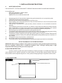
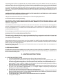
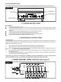
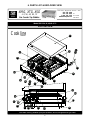
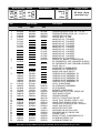
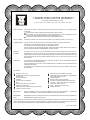
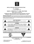
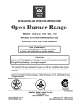
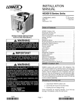
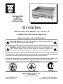
INSTALLATION
AND
OPERATING
INSTRUCTIONS
Griddles
Models: XSG, XTG, XMG-24, -36, -48, -60, -72
INTENDED FOR OTHER THAN HOUSEHOLD USE
RETAIN THIS MANUAL FOR FUTURE REFERENCE
!
FOR YOUR SAFETY: Do not store or use gasoline or other flammable vapors and
liquids in the vicinity of this or any other appliance.
!
!
WARNING: Improper installation, adjustment, alteration, service or maintenance can
cause property damage, injury or death. Read the Installation, Operating and
Maintenance Instructions thoroughly before installing or servicing this equipment.
!
This equipment has been engineered to provide you with year round dependable service when used
according to the instructions in this manual and standard commercial kitchen practices.
Instructions must be posted in a prominent location. All safety precautions must be taken in the
event the user smells gas. Safety information can be obtained from your local gas supplier.
R
CERTIFIED
SANITATION
NSF/ANSI 4
R
R
Form #U4179A 3/05
BAKERS PRIDE OVEN CO., INC.
30 Pine Street
New Rochelle, NY 10801
(914) 576-0200 Phone
(914) 576-0605 Fax
(800) 431-2745 US & Canada
www.bakerspride.com WebAddress
1
CONTENTS
SECTION
ITEM
PAGE
1. INSTALLATION INSTRUCTIONS
A
B
C
D
E
3
Safety Precautions
Unpacking Instructions
Gas Connections
Electric Installation (XSG model only)
Leveling Adjustment
3
3
3
4
4
2. LIGHTING INSTRUCTIONS
A
B
4
Lighting Instructions
Shutdown Instructions
4
5
3. CLEANING INSTRUCTIONS
5
4. MAINTENANCE INSTRUCTIONS
5
5. WIRING DIAGRAM (XSG ONLY)
5
6. PARTS LIST & EXPLODED VIEW
6
7. WARRANTY
8
GAS SPECIFICATIONS
Propane Gas
BTU/HR @ 10” W.C.
Model Number
XSG, XTG, XMG
XSG, XTG, XMG
XSG, XTG, XMG
XSG, XTG, XMG
XSG, XTG, XMG
-24
-36
-48
-60
-72
Natural Gas
BTU/HR @ 3.5” W.C.
60,000
90,000
120,000
150,000
180,000
60,000
90,000
120,000
150,000
180,000
XSG units are equipped with snap action thermostats and standing pilot systems. This griddle must have 115V, 60 Hz
electrical power to operate the main burners. This appliance will not operate during a power failure. No attempt
should bemadetooperate this gas appliance during power failure.
XTG units are equipped with throttle type thermostat and standing pilot (no pilot safety provided)
XMG units are equipped with manual gas valves, and standing pilot (no pilot safety provided). No griddle plate
temperature control is provided.
2
1. INSTALLATION INSTRUCTIONS
A.
SAFETY PRECAUTIONS
FOR YOUR SAFETY, THE FOLLOWING SAFETY PRECAUTIONS SHOULD BE FOLLOWEDAND ENFORCED.
IFYOU SMELLGAS:
·
SHUT OFF GAS SUPPLY TOAPPLIANCE
EXTINGUISH OPEN FLAMES
·
IMMEDIATELYCALLYOUR GAS SUPPLIER
1.
2.
3.
4.
5.
6.
7.
8.
9.
10.
11.
12.
Aseparate gas shut-off valve should be installed in the gas line ahead of the unit, as required by codes.
LIGHTING: Follow the instructions on page 5.
At least 24 inchesmustbeprovidedatthefrontofunitforservicing.
When installing, never enclose the bottom area of the unit with a raised curb or other construction that would
obstruct the flow of air into the unit.
This unit may be operated with 0” (side and back) minimum clearance to non-combustible construction
materials.
This installationmustconform to local codes, or in absence of local codes to the National FuelGasCodeANSI
Z223.1, latest edition. In Canada it must conform to current National Standard CAN/CGA B 149.1 (natural
gas) or CAN/CGA B 149.2 (propane) Installation Code for Gas BurningAppliances & Equipment.
Electrical diagram (model XSG only) is located on the right side of the unit.
The appliance and its individual shut-off valve must be disconnected from the gas supply piping system during
any pressure testing of that system at test pressures in excess of 1/2” psi (3.45 kPa).
The appliance must be isolated from the gas supply piping system by closing its individual manual shut-off
valve during any pressure testing of the gas supply piping system at test pressures equal to or less than 1/2”
psi (3.45kPa).
This appliancemustbeinstalledunder a ventilation hood.
Do not obstruct the flow of combustion and ventilation air.
The area around this or any other gas appliancemustalways be kept free and clear from combustibles.
RETAIN THIS MANUAL FOR FUTURE REFERENCE.
IMPORTANT: Before using your Baker's Pride griddle, the protective coating that was applied at the factory
must be completely removed with a commercial de-greaser. After a through cleaning apply a high
temperature salt free frying oil and your unit is ready to use.
B. UNPACKING INSTRUCTIONS:
Carefully unpack the griddle and inspect immediately for shipping damages. Your Griddle was shipped in a
carton designed to give maximum protection in normal handling. It was thoroughly inspected before leaving the
factory and the carrier accepted and signed for it. File any claims for shipping damage or irregularities with the carrier.
C. GAS CONNECTIONS
Figure “A”
MAIN SHUT-OFF VALVE
PRESSURE REGULATOR
FLUE
3
A separate gas shut off valve (supplied with unit) must be installed in the gas line ahead of the unit, as required by
codes (see Fig.A)..Gassupplylinemustbe¾”orlarger.Ifflexiblesemirigidconnectionsareused, the inside diameter
must be the equivalent of ¾” iron pipe or larger. All connections of the flexible and semi rigid type must be AGA listed
and comply with applicable ANSI standards. Make sure gas piping is clean and free of dirt, piping compound and
obstruction. To insuremaximum operating efficiency, this appliance must be connectedwith a Gas Supply Line of solid
pipe or with a Commercial Type Flexible Connector with I.D. (inside diameter) equal or larger than the gas pipe inlet on
this appliance.
CAUTION: BEFORE LIGHTING, CHECKALLJOINTS IN THE GAS SUPPLY LINE FOR LEAKS. USE SOAPAND
WATER SOLUTION. DO NOTUSEOPENFLAME.
If the gas connections are leak-free, the unit is ready to use. Follow the lighting instructions.
D. ELECTRIC INSTALLATION (XSG ONLY)
This appliance when installed must be electrically grounded in accordance with local codes, or in the
absence of local codes, with the National Electrical Code, ANSI/NFPA 70, or the Canadian Electrical Code,
CSAC22.2, as applicable.
The installation of electric wiring from the electric meter, the main control box, and the outlet to the electric appliance
must be electrically grounded in accordance with local codes, or in the absence of local codes with the National
Electric Code ANSI/NFPA 70. In Canada, follow the Canadian Electric Code CSA-C 22.2. All work should be done by
qualified installation personnel.
Electrical diagram (model XSG only) is located on the right side of the unit.
WARNING-ELECTRICALGROUNDING INSTRUCTION
This appliance is equipped with a three-prong (grounding) plug for your protection against shock hazard and
should be plugged directly into a properly grounded three-prong receptacle. Do not cut or remove the
grounding prong from this plug.
Thermostats do not have to be turned off to turn off your griddle. The ON/OFF toggle switch allows the thermostats to
remain set at your cooking temperature when the griddle is OFF. When the main switch is ON the griddle automatically
heats to your pre-set cooking temperature.
Red indicator lights next to the thermostats are ON when the burners are in operation. When the set temperature is
reached, the light will goOFF.
E. LEVELINGADJUSTMENT
All griddles are equipped with adjustable legs to provide a means for proper leveling during installation. The griddle can
be leveled by turning the bottom of the legs until the desired position is achieved. After leveling, the manifold should
then be connected to the gas line.
2. LIGHTING INSTRUCTIONS
A. LIGHTING INSTRUCTIONS
1. Turn off all thermostats or gas controls and main Shut-off valve and wait 5 minutes.
2. Turn the main gas valve to ON position and light standing pilots through the holes in the front panel. (FIG.
B) The pilot assembly is located about 10” into the unit from the front panel. Use a BBQ match or a lighter
at least 10” long. Alternatively pilots are also accessible from the bottom of the unit and the distance is
approximately 6”. Insert a match or a lighter from the bottom of the unit while watching through the lighting
hole in the front panel to make sure all pilots light correctly.
3. Repeat the above step for all standing pilots. There should be slight yellow tip on the pilot flame. Make sure all
the pilots are lit. Pilot should be approximately ½”- ¾” in height. Adjust as required by turning the pilot
adjusting screw located on themanifold pipe.
4. Turn the toggle switch on the front panel toONposition(XSGmodelonly)
5. Set all thermostats to desired temperature. All burners must light and burn evenly. Flames are to be blue with
little or no traces of white or yellow. If they exhibit excessivewhiteoryellow flames, adjust the burner shutters.
Re-light burners and re-check. Repeat as required.
6. The red indicator light on XSGmodel will indicate that themainburner is in operation.
7. To relight follow steps 1-5.
4
B. SHUTDOWN INSTRUCTIONS
For complete shutdown turn all thermostats, toggle switch (model XSG ONLY) andmaingasvalvetoOFFposition.
Figure “B”
Lighting Hole
Thermostat
On/Off Switch
Grease Drawer
Red Indicator Light
3. CLEANING INSTRUCTIONS
A. CLEANING
Clean the unit regularly after use.
To clean griddle plate, use a fine grain stone or warm water and cleanser. Occasionally clean the griddle
with vinegar when the griddle is cool, or club soda while the griddle is still hot. This will help maintain a clean,
new look.
Grease drawer must be emptied as required. Do not allow grease to overflow.
Usemildsoapordetergent to clean chassis and stainless steel parts.
To service burners or pilots TURNOFFGASSUPPLYandremovefrontpanel.
Disconnect the power supply before cleaning or servicing.
4. MAINTENANCE INSTRUCTIONS
A. MAINTENANCE
To provide proper operation and insure the safety of the user, this equipment must be maintained and serviced by a
trained maintenance person or an authorized service agency at regular intervals. Disconnect the power supply to
appliance before cleaning or servicing.
1.
Burner ports must be thoroughly cleaned. Venturimustbefreefromgreaseandlint.
2.
All places where oil, grease or food can accumulatemustbekeptclean all the time.
3.
Pilot light must be kept clean and adjusted at the proper flame height to assure constant ignition and to
prevent
fire flash-outs caused by delayed ignition.
4.
Appliance flue has to be kept clean and free of any obstruction to ensure unrestricted flow of combustion
products from the unit.
5.
Carelessness, abusive handling, or altering equipment can shorten the life of the equipment and jeopardize
the limited warranty offered by Baker's Pride.
If you have any questions concerning the installation, operation, maintenance or service of this product
please contact Bakers Pride’s Technical Service Department at (800) 431-2745 US & Canada.
5. WIRING DIAGRAM - MODEL XSG ONLY (See Figure C)
Figure “C”
Solenoid
Valve
Coils
120VAC
Black
72”
60”
48”
36”
24”
C1
C2
C3
C4
C5
C6
White
Electrical Box
Green
Thermostats
450°F
T6
T5
T4
T3
T2
Control Panel
N6
N4
N5
5
N3
N2
Power
Switch
T1
N1
Neon
Indicator
Lamps
6. PARTS LIST & EXPLODED VIEW
XMG, XTG, XSG
30 Pine Street • New Rochelle • New York • 10801
914 / 576 - 0200
914 / 576 - 0605 fax
1 - 800 - 431 - 2745 US & Canada
www.bakerspride.com web address
-24, 36, 48, 60, 72
Gas Counter Top Griddles
BAKERS
PRIDE
Model XSG-24,36,48,60 & 72
EXPLODED VIEW
Cookline
9
SERIES
2
1
13
11
15
21
22
10
16
8
23
4
3
24
17
7
11
13
25
14
8
28
5
Page 1 of 2
18 6
7 19 26
27
12
10
Note: When ordering, ALWAYS specify Part #, Model #, Serial #, Voltage/Phase & type of Gas.
6
2/04
Model Number - Width
XMG
-24”
XTG
-36”
XSG
-48”
Item
1
2
3
4
5
6
7
Serial Number
L.P.
-72”
XMG
XSG
M1148A
M1009A
R3205A
R3222P
R1153A
R1154A
R1155A
R1156A
R1157A
M1148A
M1009A
R3205A
R3222P
M1148A
M1009A
R3205A
R3222P
N3084A
R1142A
R1143A
R1144A
R1145A
R1146A
N3084A
PRESSURE REGULATOR, 3/4", 3.5" WC
PRESSURE REGULATOR, 3/4", 10" WC, LP
ORIFICE #38, NAT GAS
ORIFICE #52, L.P. GAS
MANIFOLD 24", T-SHAPED
MANIFOLD 36", T-SHAPED
MANIFOLD 48", T-SHAPED
MANIFOLD 60", T-SHAPED
MANIFOLD 72", T-SHAPED
MANIFOLD 24", L-SHAPED
MANIFOLD 36", L-SHAPED
MANIFOLD 48", L-SHAPED
MANIFOLD 60", L-SHAPED
MANIFOLD 72", L-SHAPED
ELBOW 3/8", BRASS, COMPRESSION
BJ THERMOSTAT, 450F (W/KNOB & SLEEVE)
KX THERMOSTAT, 450F (W/KNOB & SLEEVE)
VALVE, LML-15
KNOB 450F, BJ THERMOSTAT
KNOB 450F, KX THERMOSTAT
KNOB, GAS VALVE ON-OFF
GRIDDLE PLATE ASSEMBLY 24"
GRIDDLE PLATE ASSEMBLY 36"
GRIDDLE PLATE ASSEMBLY 48"
GRIDDLE PLATE ASSEMBLY 60"
GRIDDLE PLATE ASSEMBLY 72"
LEG 6", ADJUSTABLE
PILOT BRACKET ASSEMBLY
PILOT BURNER
BURNER, HORSE SHOE
BRASS ORIFICE FITTING, ELBOW 3/8"
HEAT SHIELD, FRONT
GREASE DRAWER
SWITCH, TOGGLE SPST ON/OFF
VALVE, PILOT DOUBLE 1/8X27 x 3/16"
VALVE, PILOT SINGLE 1/8X27 x 3/16"
PRESSURE TAP NOZZLE (NOT SHOWN)
VALVE, GAS SHUT-OFF
INDICATOR LIGHT, RED
SOLENOID VALVE, DUAL GAS
SOLENOID VALVE, SINGLE GAS
POWER CORD
BRASS FITTING, COMPRESSION 3/8"
ALUMINUM TUBING 3/16"
ALUMINUM TUBING 3/8"
M1461A
S1360A
S1361A
9
10
11
12
13
14
15
16
17
18
19
20
21
22
23
24
25
26
27
28
2/04
G8001U
G8002U
G8003U
G8004U
G8005U
S1218A
G8062U
M1463A
L5104A
N3083A
G8057K
G8061K
R3020A
R3021A
N3068P
R3206A
R3020A
R3021A
N3068P
R3206A
N3089A
N5854A
N5856A
N3089A
N5854A
N5856A
(Model XSG Only)
Description
XTG
S1094A
G8106U
G8102A
G8103A
G8104A
G8105A
S1218A
G8062U
M1463A
L5104A
N3083A
G8057K
G8061K
120 Volts, 1 Amp
Other
R3032A
8
Voltage, Amps
Natural
-60”
Part Number
N3084A
M1465A
Type of Gas
S1218A
G8062U
M1463A
L5104A
N3083A
G8057K
G8061K
M1037A
R3020A
R3021A
N3068P
R3206A
P1168A
R3201A
R3200A
P6004A
N3089A
N5854A
N5856A
Note: When ordering, ALWAYS specify Part #, Model #, Serial #, Voltage/Phase & type of Gas.
7
Page 2 of 2
7. BAKERS PRIDE LIMITED WARRANTY
30 Pine Street New Rochelle, New York 10801
914 / 576 - 0200 • US & Canada: 1 - 800 - 431 - 2745 • fax 914 / 576 - 0605
WHAT IS COVERED
This warranty covers defects in material and workmanship under normal use, and applies only to the original purchaser
providing that:
! The equipment has not been accidentallyorintentionallydamaged, altered or misused;
! The equipment is properly installed, adjusted, operated and maintained in accordance with National and local
codes, and in accordance with the installation instruction provided with the product;
! The serial number rating plate affixed to the equipment has not been defaced or removed.
WHO IS COVERED
This warranty is extended to the original purchaser and applies only to equipment purchased for use in the U.S.A.
COVERAGE PERIOD
Cyclone Convection Ovens: BCOModels: One (1) Year limited parts and labor; (1) Year limited doorwarranty.
GDCOModels: Two (2) Year limited parts and labor; (2) Year limited door warranty.
CO11 Models: Two (2) Year limited parts and labor; (5) Year limited doorwarranty.
All Other Products: One (1) Year limited parts and labor. Warranty period begins the date of dealer invoice to customer or
ninety (90) days after shipment date from BAKERS PRIDE - whichever comes first.
WARRANTY
COVERAGE
This warranty covers on-site labor, parts and reasonable travel time and travel expenses of the authorized service
representative up to (100) miles, round trip, and (2) hours travel time. The purchaser, however, shall be responsible for all
expenses related to travel, including time, mileage and shipping expenses on smaller counter models that may be carried into
a Factory Authorized Service Center, including the following models: PX-14, PX-16, P18, P22S, P24S, PD-4, PDC, WS
Series and BK-18.
EXCEPTIONS
All removable parts in BAKERS PRIDE Char-broilers, including but not limited to: Burners, Grates, Radiants, Stones and
Valves, are covered for a period of SIXMONTHS.
All Ceramic Baking Decks are covered for a period of THREE MONTHS. The installation of these replacement decks is the
responsibility of the purchaser.
The extended Cyclone door warranty years 3 through 5 is a parts only warranty and does not include labor, travel, milage or
any other charges.
EXCLUSIONS
Failures caused by erratic voltages or gas supplies,
Unauthorized repair by anyone other than a BAKERS PRIDE
Factory Authorized Service Center,
Damage in shipment,
Alteration, misuse or improper installation,
Thermostats and safety valves with broken capillary tubes,
Accessories — spatulas, forks, steak turners, grate lifters,
oven brushes, scrapers, peels, etc.,
Freight — other than normal UPS charges,
Ordinary wear and tear.
Negligence or acts of God,
Thermostat calibrations after (30) days from equipment
installation date,
Air and Gas adjustments,
Light bulbs,
Glass doors and door adjustments,
Fuses,
Char-broiler work decks and cutting boards,
Tightening of conveyor chains,
Adjustments to burner flames and cleaning of pilot burners,
Tightening of screws or fasteners,
INSTALLATION
Leveling and installation of decks, as well as proper installation and check out of all new equipment — per appropriate
installation and use materials — is the responsibility of the dealerorinstaller, notthemanufacturer.
REPLACEMENT
PARTS
BAKERS PRIDE genuine Factory OEM parts receive a (90) day materials warranty effective from the date of installation by a
BAKERS PRIDE Factory Authorized Service Center.
This Warranty is in lieu of all other warranties, expressed or implied, and all other obligations or liabilities on the manufacturers part. BAKERS PRIDE
shall in no event be liable for any special, indirect or consequential damages, or in any event for damages in excess of the purchase price of the unit. The
repair or replacement of proven defective parts shall constitute a fulfillment of all obligations under the terms of this warranty.
Form #U4177A 3/04
8