1
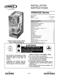
INSTALLATION
MANUAL
,?u2006 Lennox industries ]nc+
Dallas, Texas, USA
HSXB15 Series Units
CONDENSING
UNITS
504,710M
03/06
Supersedes 11/05
RETAIN THESE INSTRUCTIONS
FOR FUTURE REFERENCE
WARNING
A IMPORTANT
_
j_jj
Technical
Publications
Litho U.S.A.
HSXB15 Outdoor Unit ..........................
Shipping & Packing List ........................
General Information ...........................
Parts Arrangement & Unit Dimensions ...........
Setting The Unit ...............................
Electrical .....................................
Refrigerant Piping .............................
Flushing Existing Line Set & Indoor Coil ..........
Refrigerant Metering Device ....................
Manifold Gauge Set ...........................
Service Valves ................................
Leak Testing ..................................
Evacuation ...................................
Start-Up ......................................
Refrigerant Charging ...........................
System Operation .............................
Maintenance ..................................
Optional Accessories ..........................
Homeowner Information ........................
Thermostat Operation ..........................
Start-Up & Performance Check List ..............
1
1
2
2
3
4
4
7
9
9
9
10
10
11
11
13
15
15
15
16
16
WARNING
HSXB15 outdoor units use R-410A HFC refrigerant. This
unit must be installed with a matching indoor coil and line set
as outlined in the Lennox Engineering Handbook, HSXB15
outdoor units are designed for use in expansion valve systems only. They are not designed to be used with other refrigerant flow control devices, The filter drier is factory-installed.
The Lennox Engineering Handbook lists indoor TXV kits that
must be ordered separately.
1 - Assembled HSXB15 outdoor unit
2 - Grommets (for liquid and suction lines)
1 - Bushing (for low voltage wiring)
Check equipment for shipping damage. If you find any
damage, immediately contact the last carrier.
03/06
IIIB+IIIIIIIIIIIHIIIIIIIIIIIll
Page 1
504,710M
IIIIIIIIIIIIIIIIIIIIIIIIIIIIIII
COMPRESSOR
RUN
CAPACITOR
SYSTEM OPERATION
MONITOR
CONTACTOR
/
VAPOR LINE
" GROUND
LUG
INLET AIR
,_
VAPOR VALVE
INLET
AIR
- AND GAUGE PORT
COMPRESSOR
POWER
TERMINALS
LIQUID LINE
" SERVICE VALVE
AND GAUGE
PORT
"_ FILTER DRIER
DISCHARGE
LINE
LOW PRESSURE
SWITCH
HIGH PRESSURE
SWITCH
"_
INLETAIR
TOP VIEW
PARTS ARRANGEMENT
ELECTRICAL
t
INLETS
_'_,,
VAPOR LINE INLET'_.
\\
LIQUID LINE INLET\xX\_
C
X
_
tDISCHARGE
AIR
.........................................................................
.......................................................................................................
4-1/2
A
(114)
2-9/16
(65)
D
-
(,)
II
I
_-_142)_1_
2
F -_C142_
1-3/8..._
!_
(35) "Yll
(51)
rE.
I_,..J 6-1/16L,=
"'-I (154)I_'
SIDE VIEW
Figure
1
HSXB15 Model
Dim.
-024
-030,-036,-042
-048
-060
A
27-7/8 (708)
30-7/8 (784)
34-7/8 (886)
40-7/8 (1038)
B
25-7/8 (657)
32-1/8 (816)
32-1/8 (816)
32-1/8 (816)
C
29-7/8 (759)
34-1/16 (865)
34-1/16 (865)
34-1/16 (865)
D
12-1/4 (311 )
12-3/4 (324)
13-3/4 (349)
19-3/4 (502)
E
22-7/16 (570)
26-5/8 (676)
26-5/8 (676)
26-5/8 (676)
These instructions are intended as a general guide and do
not supersede local codes in any way. Consult authorities
who have jurisdiction before installation.
Table 1
Torque
Requirements
Part
Recommended
Service valve cap
Sheet metal screws
8 ft.- lb.
16 in.- lb.
Torque
11 NM
2 NM
F
14-7/16 (367)
18-5/8 (473)
18-5/8 (473)
18-5/8 (473)
G
22-1/8 (562)
28-1/8 (718)
28-1/8 (718)
28-1/8 (718)
Machine screws #10
28 in.- lb.
3 NM
H
2-7/8 (73)
3-7/8 (98)
3-7/8 (98)
3-7/8 (98)
Compressor bolts
90 in.- lb.
10 NM
J
5-1/2 (140)
7-1/2 (191)
7-1/2 (191)
7-1/2 (191)
Gauge port seal cap
8 ft.- lb.
11 NM
Page 2
504710M
03/06
CAUTION
Referto unitdimensions(figure1,on page2) forsizing
mounting
slab,platforms
or supports.Refertofigure2 for
installation
clearances.
Installation
Slab Mounting
Clearances
notes
see
"_
see
notes
When installing a unit at grade level, the top of the slab
should be high enough above the grade so that water from
higher ground would not collect around the unit. See figure
3. Slab may be level or have a slope tolerance away from
the building of not more than 2 degrees or 2 inches per 5
feet (51 mm per 1524 mm)+
Slab Mounting
INSTALL UNIT LEVEL OR,
IF ON A SLOPE, MAINTAIN
SLOPE TOLERANCE OF 2
DEGREES (OR 2 INCHES
PER 5 FEET [51 MM PER
1.5 M]) AWAY FROM
BUILDING STRUCTURE.
see
notes
DISCHARGE
AIR
,_
STRUCTURE
BUILDING
i-
NOTES A service access clearance of 30" (762 mm) must be maintained in
front of the service access panel, Clearance to one side must be 36+'
(914 mm), Clearance to one of the remaining two sides may be 12"
(305 mm) and the final side may be 6+'(152 mm),
MOUNTING
SLAB
/
A clearance of 24" (610 mm) must be maintained between two units.
48" (1219 mm) clearance required on top of unit. Maximum soffit
overhang is 36" (914 mm).
Figure
--r
GROUNDLEVEL
2
Figure 3
CAUTION
Roof Mounting
Install unit at a minimum of 4 inches above surface of the
roof, Care must be taken to ensure weight of unit is properly distributed over roof joists and rafters. Either redwood or
steel supports are recommended.
Page 3
HSXB15
SERIES
4. Install low voltage wiring from outdoor to indoor unit
and from thermostat to indoor unit, See figure 4,
In the U.S.A., wiring must conform with current local codes
and the current National Electric Code (NEC). In Canada,
wiring must conform with current local codes and the current Canadian Electrical Code (CEC).
Refer to the furnace or blower coil installation instructions
for additional wiring application diagrams and refer to unit
nameplate for minimum circuit ampacity and maximum
overcurrent protection size.
Typical
Wiring
Diagram
Outdoor Unit
Thermostat
/-q
Indooj.Unit
/.--.
p.....
t RJ
___
L_J
R- System
Operation
J
(R)
v
v
®
I
A, WARNING
Field Low Voltage
@
heat
[_Y1
Q
Outdoor
coolinq
indoor
tG)
(G)
blower
./_C
Q
common
Outdoor
Unit
NOTE - see unit widng diagram for power supply connections. If indoor unit is not equipped with blower relay It must
be field-provided and installed (P-8-3251 or equivalent).
Figure 4
1, Install line voltage power supply to unit from a properly
sized disconnect switch,
Outdoor
2, Ground unit at unit disconnect switch or to an earth
ground,
B4
OUTDOOR
NOTES
• Connect conduit to the control box using a proper
conduit fitting.
• Units are approved for use only with copper conductors.
• 24V, Class II circuit connections are made in the
low voltage junction box, Refer to figure 5 for field
wiring diagram.
• A complete unit wiring diagram is located inside
the unit's front access panel,
AWG #
Insulation type
less than 100' (30m)
18
more than 100' (30m)
16
color-coded,
temperature
,
o
, ,
rating 35 C minimum
3, Install room thermostat (ordered separately) on an inside wall approximately in the center of the conditioned
area and 5 feet (1,5 m) from the floor, It should not be
installed on an outside wall or where it can be effected
by sunlight, drafts or vibrations,
64OUTDOOR FAN
G)
03/06
GROUND
KI
COMPRESSOR
]APACITOR
HIGH
]OMMON
CONTACTOR
LUG,S.
L2
L1
z_
BLACK=COMMON
ORANGE-RUN
PURPLE-
206=230/60/I
Cl2
DUAL
CAPACITOR
CAPADITOR
_NOTEFOR USE WITH
COPPER
ONLY,REFER
TO UNIT
CONDUCTORS
RATING
PLATE
FOR MINIMUM
CIRCUIT
AMPACITY
AND MAXIMUM
OVERCURRENT
PROTECTION
SIZE
Z_WARNINOELECTRIC
SHUCK HAZARD,CAN
CAUSE INJURY
OR DEATH,UNIT
NUST BE GROUNDED IN
ACCORDANCE
WiTH
NATIONAL
AND LOCAL
CODES.
_LINE
VOLTAGE
FIELD
INSTALLED
Figure
5
If the HSXB15 unit is being installed with a new indoor coil
and line set, the connections should be made as outlined in
this section. If an existing line set and/or indoor coil (used
with mineral oil) is going to be used to complete the
HSXB15 system, refer to the following section which includes flushing procedures.
Page 4
504710M
Diagram
FAN
LESS
NOTE - For proper voltages, select thermostat wire
gauge per the following chart:
Wire run length
Unit Field Wiring
Fieldrefrigerantpipingconsistsof liquidandvaporlines
fromtheoutdoorunit(sweatconnections)
totheindoorcoil
(flareorsweatconnections).
UseLennoxL15(sweat,nonflare)serieslinesetsasshownintable2 or usefield-fabricatedrefrigerant
lines.Valvesizesarealsolistedintable2.
points to consider when placing and installing a high-efficiency outdoor unit:
1. Placement - Be aware that some localities are adopting sound ordinances based on how noisy the unit is
from the adjacent property not at the original installation. Install the unit as far as possible from the property
line. When possible, do not install the unit directly outside a window. Glass has a very high level of sound
transmission.
Table 2
Refrigerant
Model
No.
Line Sets
Valve Field Size
Connections
Recommended
Liquid
Line
Liquid
Line
Vapor
Line
Line Set
Vapor
Line
2. Line Set Isolation - The following illustrations demonstrate procedures which ensure proper refrigerant line
set isolation. Figure 6 shows how to place the outdoor
unit and line set. Figure 7 shows how to install line sets
on horizontal runs. Figure 8 shows how to install line
sets on vertical runs. Finally, figure 9 shows how to
make a transition from horizontal to vertical.
L15
Line Sets
-024
3/8 in.
3/4 in.
3/8 in.
3/4 in.
L15-41
-030
-036
(10mm)
(19mm)
(10mm)
(19mm)
15 ft. - 50 ft.
(4.6 m - 15 m)
-042
3/8 in.
7/8 in.
3/8 in.
7/8 in.
L15-65
-048
(10 mm)
(22 ram)
(10 ram)
(22 ram)
15 ft.-50 ft.
(4.6 m - 15 m)
-060
3/8 in.
1-1/8 in.
3/8 in.
1-1/8 in.
Field
(10 mm)
(29 ram)
(10 ram)
(29 ram)
Fabricated
Outside
NOTE - Units are designed for line sets of up to 50' (15m).
Refrigerant
Connections
- HSXB15
with New Indoor Coil and Line Set
Unit Placement
Install unit away
from windows and
neighbors' windows
Matched
and Installation
_
_x
--
NX"
If an existing indoor coil that was equipped with an
RFCI metering device is being replaced, the liquid line
must also be replaced prior to the installation of the
HSXB15 unit.
If refrigerant lines are routed through a wall, seal and isolate the opening so vibration does not transmit to building,
Installing Refrigerant
Line
During the installation of any heat pump or a/c system, it is
important to properly isolate the refrigerant lines to prevent
unnecessary vibration. Line set contact with the structure
(wall, ceiling or floor) causes some objectionable noise
when vibration is translated into sound. As a result, more
energy or vibration can be expected. Closer attention to
line set isolation must be observed. Following are some
Refrigerant
To hang line set from joist or rafter,
use either metal strapping material
or anchored heavy nylon wire ties.
Two 90 ° elbows installed in line set will reduce line set vibration.
Figure
Line Sets: Installing
Horizontal
6
Runs
WIRE TIE
(Around vapor line only)
8 feet
STRAPPING MATERIAL
(Around vapor line only)
\
feet
METAL
SLEEVE
TAPE OR WIRE TIE
Strap the vapor line to the joist or
rafter at 8 ft. intervals then strap
the liquid line to the vapor line.
FLOOR JOIST OR
ROOF RAFTER
TAPE OR WIRE TIE
Figure
7
Page 5
HSXB15
SERIES
Refrigerant
Line Sets: Installing Vertical Runs (new construction
shown)
NOTE - Similar installation practices should be used if line set is to be installed on exterior of outside wall.
OUTSIDE WALL
IMPORTANT - Refrigerant
lines must not contact wall.
VAPOR LINE
LI
UID LINE
WIRE TIE
s
INSIDEWALL
STRAP
SLEEVE
VAPOR LINE WRAPPED
WITH ARMAFLEX
IMPORTANT!
Refrigerant
lines must
not contact
structure.
WIRE TIE
LIQUID
WOOD BLOCK
OiTSIDE
WALL
iiiiiiiiiiiiiiiiiiiiiiiiiiiiiiiiiiiiiiiiiiiiiiiiiiiiiiiiiiiiiiiiiiiiiiiiiiiiiiiiiiiiiiiiiiiiiiiiiiiiiiiiiiiiiiiiii_
WIRE TIE
STRAP
CAULK
PVC PIPE
FIBERGLASS
INSULATION
SLEEVE
Figure
Refrigerant
Line Sets:
Transition
8
From Vertical
ANCHORED
HEAVY NYLON
WIRE TIE
AUTOMOTIVE
MUFFLER-TYPE
HANGER
WALL
STUD
WALL
STUD
METAL
SLEEVE
Strap Liquid
Line To Vapor Line
Strap Liquid Line
To Vapor Line
LIQUID LINE
UID LINE
VAPOR LINE - WRAPPED
IN ARMAFLEX
METAL
SLEEVE
Figure
Page 6
504710M
03/06
To Horizontal
9
VAPOR LINE - WRAPPED
IN ARMAFLEX
WARNING
IMPORTANT
Brazing Connection
Procedure
1, Cut ends of the refrigerant lines square (free from
nicks or dents). Debur the ends. The pipe must remain
round, do not pinch end of the line.
2+ Before making line set connections, use dry nitrogen
to purge the refrigerant piping. This will help to prevent
oxidation and the introduction of moisture into the system.
IMPORTANT
3+ Wrap a wet cloth around the valve body and copper
tube stub to protect it from heat damage during brazing. Wrap another wet cloth underneath the valve body
to protect the base paint.
NOTE - The tube end must stay bottomed in the fitting
during final assembly to ensure proper seating, sealing and rigidity.
4+ Install the field-provided thermal expansion valve (approved for use with R-410A refrigerant) in the liquid
line at the indoor coil.
5+ Use silver alloy brazing rods (5 or 6 percent minimum
silver alloy for copper-to-copper brazing or 45 percent
silver alloy for copper-to-brass or copper-to-steel
brazing) which are rated for use with R-410A refrigerant. Wrap a wet cloth around the valve body and the
copper tube stub. Remove light maroon washers from
service valves and shield light maroon stickers in order
to protect them during brazing. Braze the line set to the
service valve.
,WARNING
NOTE - If the indoor unit line and set is new, skip this section and go on to the Manifold Gauge Set section.
CAUTION
Required Equipment
You will need the following equipment in order to flush the
existing line set and indoor coil: two clean HCFC-22 recovery bottles, an oilless recovery machine with a pump down
feature, and two sets of gauges (one for use with HCFC-22
and one for use with the R-410A).
Flushing Procedure
1. Remove existing HCFC-22 refrigerant using the appropriate procedure below (see figure 10):
If the existing outdoor unit is not equipped with
shut-off valves, or if the unit is not operational
AND you plan to use the existing R-22 refrigerant
to flush the system • Disconnect all power to the existing outdoor unit.
• Connect to the existing unit, a clean recovery cylinder and the recovery machine according to the
instructions provided with the recovery machine.
• Remove all R-22 refrigerant from the existing system. Check gauges after shutdown to confirm that
the entire system is completely void of refrigerant.
• Disconnect the liquid and vapor lines from the existing outdoor unit.
Page 7
HSXB15
SERIES
Flushing
Connections
Inverted R-22 Cylinder
(Contains clean R-22 to
be used for flushing)
Low
Pressure
EXISTING VAPOR LINE
-
High
Pressure
HSXB15
UNIT
VaP°i_eLi_/aelve_[
EXISTING
INDOOR COIL
EXISTING
LIQUID
LINE
_ Sk_r_ii_ el-_ve
I
fr"
NOTE - The inverted R-22 cylinder
must contain at least the same
amount of refrigerant as was recovered from the existing system.
Tank
Inlet Return
Discharge
RECOVERY
CYLINDER
RECOVERY
MACHINE
Figure
10
ff the existing outdoor unit is equipped with
manual shut-off valves AND you plan to use NEW
R-22 refrigerant to flush the system • Start the existing R-22 system in the cooling mode
and close the liquid line valve,
• Pump all of the existing R-22 refrigerant back into
the outdoor unit, (It may be necessary to bypass
the low pressure switches to ensure complete refrigerant evacuation.)
• When the low side system pressures reach 0 psig,
close the vapor line valve.
• Disconnect all power to the existing outdoor unit.
Check gauges after shutdown to confirm that the
valves are not allowing refrigerant to flow back into
the low side of the system.
• Disconnect the liquid and vapor lines from the existing outdoor unit,
2. Remove the existing outdoor unit. Set the new R-410A
unit and follow the brazing connection procedure
which begins on the previous page to make line set
connections. DO NOT install the expansion valve at
this time. Make low voltage and line voltage connections to the new outdoor unit. DO NOT turn on power
to the unit or open the outdoor unit service valves
at this time.
3. Remove the existing refrigerant flow control orifice or
thermal expansion valve before continuing with flushing procedures. Theexisting devicesare not approved
for use with R-410A refrigerant and may prevent properflushing, Usea field-provided fitting to reconnect the
lines.
Page 8
504710M
03/06
IMPORTANT
4. Remove the pressure tap valve cores from the
HSXB15 unit's service valves. Connect an HCFC-22
cylinder with clean refrigerant to the vapor service
valve, Connect the HCFC-22 gauge set to the liquid
line valve and connect a recovery machine with an
empty recovery tank to the gauge set,
5. Set the recovery machine for liquid recovery and start
the recovery machine. Open the gauge set valves to
allow the recovery machine to pull a vacuum on the existing system line set and indoor coil.
6. Invert the cylinder of clean HCFC-22 and open its
valve to allow liquid refrigerant to flow into the system
through the vapor line valve. Allow the refrigerant to
pass from the cylinder and through the line set and the
indoor coil before it enters the recovery machine.
7. After all of the liquid refrigerant has been recovered,
switch the recovery machine to vapor recovery so that
all of the HCFC-22 vapor is recovered. Allow the recovery machine to pull a vacuum on the system,
NOTE -A single system flush should remove all of the
mineral oil from the existing refrigerant lines and indoor coil, A second flushing may be done (using clean
refrigerant) if insufficient amounts of mineral oil were
removed during the first flush. Each time the system
is flushed, you must allow the recovery machine
to pull a vacuum on the system at the end of the
procedure.
8, Close the valve on the inverted HCFC-22 drum and
the gauge set valves. Pump the remaining refrigerant
out of the recovery machine and turn the machine off,
9, Use dry nitrogen to break the vacuum on the refrigerant lines and indoor coil before removing the recovery
machine, gauges and HCFC-22 refrigerant drum. Reinstall pressure tap valve cores into HSXB15 service
valves.
The liquid line and vapor line service valves and gauge
ports are used for leak testing, evacuating, charging and
checking charge, Each valve is equipped with a service
port which has a factory-installed Schrader valve. A service port cap protects the Schrader valve from contamination and serves as the primary leak seal,
Front-Seated
Service Valve (Liquid Line)
The front-seated service valve is shown in figure 12. When
this valve is closed, the service port is open to the line set.
Access the service port and open and close valves as described in the following paragraphs,
10. Install the field-provided expansion valve (approved
for use with R-410A refrigerant) in the liquid line at the
indoor coil.
Front-Seated
Liquid Line Service
(Valve Shown Closed)
Valve
SERVICE
Insert hex wrench here
HSXB15 units are used in check expansion valve systems
only. See the Lennox Engineering Handbook for approved
TXV match-ups and application information,
STEM
CAP
Check expansion valves equipped with Chatlefffittings are
available from Lennox. Refer to the Engineering Handbook for applicable expansion valves for use with specific
match-ups.
To
indoor coil
To outdoor coil
(Valve Shown Open)
If you install a check expansion valve with an indoor
coil that includes a fixed orifice, remove the orifice before installing the check expansion valve.
insert hex wrench here
SERVICE
PORT
See figure 11 for installation of the check expansion valve,
STEM
CAP
Metering
Device
O-RING
EXPANSION
/
//
Installation
O-RING
VALVE &
To
indoor coil
(See NOTE)
Service port Is open to
line set when valve is
closed (front seated)
STRAINER
DISTRIBUTOR
_'_%...
Figure
_ LIQUID LINE
STUB
To Access
NOTE - If necessa04 remove R-22 flow control device (fixed
odfice/thermal expansion valve) from existing line set before
installing R-410A approved expansion valve and o-ring.
Figure
To outdoor coil
Schrader
12
Port:
1, Remove access panel,
2. Remove service port cap with an adjustable wrench,
3, Connect gauge to the service port.
11
4, When testing is completed, replace service port cap,
Tighten finger tight, then torque per table 1 (Page 2),
Manifold gauge sets used with systems charged with
R-410A refrigerant must be capable of handling the higher
system operating pressures. The gauges should be rated
for use with pressures d 0 - 800 on the high side and a low
side d 30" vacuum to 250 psi with dampened speed to 500
psi. Gauge hoses must be rated for use at up to 800 psi of
pressure with a 4000 psi burst rating,
To Open Front-Seated
Service Valves:
1, Remove stem cap with an adjustable wrench,
2, Use a service wrench with a hex-head extension
(3/16" for liquid-line valve sizes; 5/16" for vapor-line
valve sizes) to backthe stem out counterclockwise as
far as it will go,
3, Replace the stem cap, Tighten finger tight, then torque
per table 1 (Page 2),
To Close Front-Seated Service Valves:
1. Remove the stem cap with an adjustable wrench.
Page 9
HSXB15
SERIES
2, Use a service wrench with a hex-head extension
(3/16" for liquid-line valve sizes; 5/16" for vapor-line
valve sizes) to turn the stem clockwise to seat the
valve. Tighten it firmly,
6, After a few minutes, open a refrigerant port to check
that an adequate amount of refrigerant has been added fordetection (refrigerant requirements will varywith
line lengths). Checkalljoints for leaks. Purge dry nitrogen and R-410A mixture. Correct any leaks and recheck.
3, Replace the stem cap, Tighten finger tight, then torque
per table 1 (Page 2).
A IMPORTANT
After the line set has been connected to the indoor and outdoor units, the line set connections and indoor unit must be
checked for leaks,
I
WARNING
I
A.WARNING
Evacuating the system of noncondensables is critical for
proper operation of the unit. Noncondensables are defined
as any gas that will not condense under temperatures and
pressures present during operation of an air conditioning
system. Noncondensables and water vapor combine with
refrigerant to produce substances that corrode copper piping and compressor parts,
IMPORTANT
1, Connect manifold gauge set to the service valve ports:
• low pressure gauge to vapor line service valve
• high pressure gauge to liquid line service valve
2, Close manifold gauge set valves. Connect the center
manifold hose to an upright cylinder of R-410A,
3, Connect micron gauge.
Using an Electronic Leak Detector
1, Connect the high pressure hose of the manifold gauge
set to the vapor valve service port. (Normally, the high
pressure hose is connected to the liquid line port, however, connecting it to the vapor port helps to protect the
manifold gauge set from damage caused by high pressure,)
2+ With both manifold valves closed, connect the cylinder
of R-410A refrigerant, Open the valve on the R-410A
cylinder (vapor only).
3+ Open the high pressure side of the manifold to allow
R-410A into the line set and indoor unit. Weigh in a
trace amount of. [A trace amount is a maximum of 2
ounces (57 g) refrigerant or 3 pounds (31 kPa) pressure.] Close the valve on the R-41OA cylinder and the
valve on the high pressure side of the manifold gauge
set. Disconnect R-410A cylinder,
4. Connect a cylinder of dry nitrogen with a pressure regulating valve to the center port of the manifold gauge
set,
5+ Adjust dry nitrogen pressure to 150 psig (1034 kPa),
Open the valve on the high side of the manifold gauge
set in order to pressurize the line set and the indoor
coil,
Page 10
504710M
03/06
4, Connect the vacuum pump (with vacuum gauge) to
the center port of the manifold gauge set,
5, Open both manifold valves and start the vacuum
pump.
6, Evacuate the line set and indoor unit to an absolute
pressure of 23,000 microns (29,01 inches of mercury), During the early stages of evacuation, it is desirable to close the manifold gauge valve at least once to
determine if there is a rapid rise in absolute pressure.
A rapid rise in pressure indicates a relatively large
leak, If this occurs, repeat the leak testing procedure,
NOTE - The term absolute pressure means the total
actual pressure within a given volume or system,
above the absolute zero of pressure, Absolute pressure in a vacuum is equal to atmospheric pressure minus vacuum pressure.
7, When the absolute pressure reaches 23,000 microns
(29.01 inches of mercury), close the manifold gauge
valves, turn off the vacuum pump and disconnect the
manifold gauge center port hose from vacuum pump.
Attach the manifold center port hose to a dry nitrogen
cylinder with pressure regulator set to 150 psig (1034
kPa) and purge the hose. Open the manifold gauge
valves to break the vacuum in the line set and indoor
unit, Close the manifold gauge valves,
This system is charged with R410A refrigerant which operates at much higher pressures than HCFC-22, The expansion valve and liquid line filter drier provided with the unit
are approved for use with R-410A. Do not replace them
with components designed for use with HCFC-22. This unit
is NOT approved for use with coils which include metering
orifices or capillary tubes,
WARNING
8, Shut off the dry nitrogen cylinder and remove the manifold gauge hose from the cylinder. Open the manifold
gauge valves to release the dry nitrogen from the line
set and indoor unit.
9, Reconnect the manifold gauge to the vacuum pump,
turn the pump on, and continue to evacuate the line set
and indoor unit until the absolute pressure does not
rise above 500 microns (29.9 inches of mercury) within
a 20-minute period after shutting off the vacuum pump
and closing the manifold gauge valves.
10, When the absolute pressure requirement above has
been met, disconnect the manifold hose from the vacuum pump and connect it to an upright cylinder of
R-410A refrigerant. Open the manifold gauge valves
to break the vacuum from 1 to 2 psig positive pressure
in the line set and indoor unit, Close manifold gauge
valves and shut off the R-410A cylinder and remove
the manifold gauge set,
1, Rotate fan to check for frozen bearings or binding,
2, Inspect all factory- and field-installed wiring for loose
connections,
3, After evacuation is complete, open the liquid line and
vapor line service valves to release the refrigerant
charge (contained in outdoor unit) into the system.
4, Replace the stem caps and secure finger tight, then
tighten an additional one-sixth (1/6) of a turn,
5, Check voltage supply at the disconnect switch. The
voltage must be within the range listed on the unit's
nameplate. If not, do not start the equipment until you
have consulted the power company and the voltage
condition has been corrected.
6, Set the thermostat for a high stage cooling demand
(Y1 and Y2 demand). Turn on power to the indoor
blower and close the outdoor unit disconnect switch to
start the unit,
7, Recheck voltage while the unit is running. Power must
be within range shown on the nameplate,
IMPORTANT
Factory Charge
Units are factory charged with the amount of R-410A refrigerant indicated on the unit rating plate. This charge is
based on a matching indoor coil and outdoor coil with 15
feet (4.6 m) line set. For varying lengths of line set, refer to
table 3 for refrigerant charge adjustment,
Table 3
Refrigerant
Charge
per Line Set Lengths
Liquid Line
Set Diameter
Ounces per 5 feet (grams per 1.52 meter)
adjust from 15 ft. (4.57m) line set*
3/8 in. (9.5mm)
3 ounces per 5 feet (85 grams per 1.52 meter)
*Add the amount shown if line length is greater than 15' (4.57m), subtract the amount shown if less than 15'.
Units
Delivered
Void of Charge
A IMPORTANT
If the system is void of refrigerant, clean the system using the following procedure:
1, Use dry nitrogen to pressurize the system and check
for leaks, Repair leaks, if possible,
2, Evacuate the system to remove as much of the moisture as possible (triple evacuation),
3, Use nitrogen to break the vacuum and install the provided filter drier in the system.
4. Evacuate the system again. Then, weigh the appropriate amount of R-410A refrigerant (listed on unit nameplate) into the system.
5. Start the unit and monitor the system to determine the
amount of moisture remaining in the oil. Use test kit
10N46 to verify that the moisture content is within the
kit's dry color range,
6. If the moisture content is not within the dry color range,
add a new filter drier between the liquid valve and the
TXV. You may have to add a new filter drier several
times to achieve the required level of dryness,
If system dryness is not verified, the compressor
will fail in the future.
Checking
Charge
The outdoor unit should be charged during warm weather.
However, applications arise in which charging must occur
in the colder months. The method of charging is determined by the unit's refrigerant metering device and the
outdoor ambient temperature.
Measure the liquid line temperature and the outdoor ambient temperature as outlined below:
Page 11
HSXB15
SERIES
1, Connect the manifold gauge set to the service valves:
• low pressure gauge to vapor valve service port
• high pressure gauge to liquid valve service port
Close manifold gauge set valves. Connect the center
manifold hose to an upright cylinder of R-410A.
2, Set the room thermostat to call for heat. This will
create the necessary load for properly charging the
system in the cooling cycle,
2, Attach high pressure gauge set and operate unit for
several minutes to allow system pressures to stabilize.
3. Compare stabilized pressures with those provided in
table 5, "Normal Operating Pressures." Minor variations in these pressures may be expected due to differences in installations. Significant differences could
mean that the system is not properly charged or that
a problem exists with some component in the system.
Pressures higher than those listed indicate that the
system is overcharged, Pressures lower than those
listed indicate that the system is undercharged. A temperature/pressure chart for R-410A refrigerant is provided in table 6 for your convenience, Verify adjusted
charge using the approach method,
4. Use the same digital thermometer you used to check
the outdoor ambient temperature to check the liquid
line temperature.
5. The difference between the ambient and liquid temperatures should match values given in table 4, If the
values don't agree with the those in table 4, add refrigerant to lower the approach temperature, or recover
refrigerant from the system to increase the approach
temperature. Be aware d the R-410A refrigerant cylinder. It will be light maroon-colored. Refrigerant should
be added through the vapor valve in the liquid state.
3, Use a digital thermometer to record the outdoor ambient temperature.
4, When the heating demand has been satisfied, switch
the thermostat to cooling mode with a set point of 68°F
(20°C). When pressures have stabilized, use a digital
thermometer to record the liquid line temperature.
5, The outdoor temperature will determine which charging method to use. Proceed with the appropriate
charging procedure.
Charge Using the Weigh-in Method Outdoor Temperature
< 65°F (18°C)
If the system is void of refrigerant, or if the outdoor ambient
temperature is cool, the refrigerant charge should be
weighed into the unit, Do this after any leaks have been repaired.
1, Recover the refrigerant from the unit,
Table 4
2, Conduct a leak check, then evacuate as previously
outlined,
Approach
3, Weigh in the unit nameplate charge,
If weighing facilities are not available or if you are charging
the unit during warm weather, follow one of the other procedures outlined below,
HSXB15-024
Approach Temperature
Liquid Line - Outdoor Ambient °F (°C)
8 + 1 (4.5 + .5)
HSXB15-030
8 + 1 (4.5 + .5)
Charge
HSXB15-036
6 + 1 (3.3 +.5)
HSXB15-042
9 + 1 (5+ .5)
HSXB15-048
8 + 1 (4.5 + .5)
HSXB15-060
12 + 1 (6.7 + .5)
Using the Approach
Model No.
Values
Method
-
Outdoor Temperature
_>65°F (18°C)
The following procedure is intended as a general guide and
is for use on expansion valve systems only. For best results, indoor temperature should be 70°F (21°C) to 80°F
(26°C). Monitor system pressures while charging.
1, Record outdoor ambient temperature
thermometer,
NOTE - For best results, the same electronic
thermometer should be used to check both outdoor
ambient and fiquid line temperatures,
using a digital
Table 5
Normal
Mode
TXV
Operating
HSXB15-024
Pressures
HSXB15-030
(Liquid
Outdoor Coil
Entering Air
Temp. °F (°C)
HSXB15-036
Liquid
Vapor
Liquid
Vapor
Liquid
Vapor
Liquid
Vapor
Liquid
Vapor
Liquid
Vapor
65 (18.3)
253
132
232
130
235
128
241
131
226
130
240
130
75 (23.9)
288
135
271
132
276
130
282
133
266
132
279
132
85 (29.4)
330
137
314
135
320
132
326
135
310
135
321
135
95 (35.0)
376
140
360
137
367
134
373
137
356
137
368
137
105 (40.6)
425
143
412
140
421
137
424
139
407
139
418
140
Page 12
504710M
03/06
+10 and Vapor +5 psig)
HSXB15-042
HSXB15-048
HSXB15-060
Table 6
R-410A
Temperature
Filter Drier
(°F) - Pressure
A filter drier is factory-installed with each HSXB15 unit.
This filter drier is installed to ensure a clean, moisture-free system. A replacement filter drier is available as
Lennox part no, 37L5201,
(Psig)
°F
Psig
°F
Psig
°F
Psig
°F
Psig
32
100.8
63
178.5
94
290.8
125
445.9
33
102.9
64
181.6
95
295.1
126
451.8
34
105.0
65
184.3
96
299.4
127
457.6
35
107.1
66
187.7
97
303.8
128
463.5
36
109.2
67
190.9
98
308.2
129
469.5
37
111.4
68
194.1
99
312.7
130
475.6
38
113.6
69
197.3
100
317.2
131
481.6
39
115.8
70
200.6
101
321.8
132
487.8
40
118.0
71
203.9
102
326.4
133
494.0
41
120.3
72
207.2
103
331.0
134
500.2
42
122.6
73
210.6
104
335.7
135
506.5
43
125.0
74
214.0
105
340.5
136
512.9
44
127.3
75
217.4
106
345.3
137
519.3
45
129.7
76
220.9
107
350.1
138
525.8
46
132.2
77
224.4
108
355.0
139
532.4
47
134.6
78
228.0
109
360.0
140
539.0
48
137.1
79
231.6
110
365.0
141
545.6
49
139.6
80
235.3
111
370.0
142
552.3
50
142.2
81
239.0
112
375.1
143
559.1
51
144.8
82
242.7
113
380.2
144
565.9
52
147.4
83
246.5
114
385.4
145
572.8
53
150.1
84
250.3
115
390.7
146
579.8
54
152.8
85
254.1
116
396.0
147
586.8
55
155.5
86
258.0
117
401.3
148
593.8
Y
56
158.2
87
262.0
118
406.7
149
601.0
C
57
161.0
88
266.0
119
412.2
150
608.1
58
163.9
89
270.0
120
417.7
151
615.4
59
166.7
90
274.1
121
423.2
152
622.7
60
169.6
91
278.2
122
428.8
153
630.1
61
172.6
92
282.3
123
434.5
154
637.5
62
175.4
93
286.5
124
440.2
155
645.0
System Operation
Monitor
The diagnostic indicator detects the most common fault
conditions in the air conditioning system, When an abnormal condition is detected, the module communicates the
specific condition through its ALERT and TRIP lights, The
module is capable of detecting both mechanical and electrical system problems, See figure 13 for the system operation monitor,
A, IMPORTANT
System
Operation
Monitor
LED
R
LED's
Figure
13
LED Functions
See table 7 for LED troubleshooting
The outdoor unit and indoor blower cycle on demand from
the room thermostat. When the thermostat blower switch
is in the ON position, the indoor blower operates continuously.
High Pressure
Switch
HSXB15 units are equipped with a high pressure switch
that is located in the liquid line of the compressor. The
switch (SPST, manual reset, normally closed) removes
power from the compressor when discharge pressure
rises above factory setting at 640 + 10 psi.
Low Pressure
Switch
HSXB15 units are also equipped with a low pressure
switch that is located in the vapor line of the compressor.
The switch (SPST, auto-reset, normally closed) removes
power from the compressor when vapor line pressure
drops below factory setting at 40 + 5 psi.
diagnostic codes.
Power LED (green) - indicates voltage within the range of
19-28VAC is present at the power connection of the module.
Alert LED (yellow) - communicates an abnormal system
condition through a unique flash code. The alert LED will
flash a number of times consecutively, pause and then repeat the process. The number of consecutive flashes, defined as the Flash Code, correlates to a particular abnormal condition
Trip LED (red) - indicates there is a demand signal from
the thermostat but no current to the compressor is detected by the module.
Flash code number corresponds to a number of LED
flashes, followed by a pause, and then repeated.
TRIP and ALERT LEDs flashing at the same time indicates
that the control circuit voltage is too low for operation.
Reset ALERT flash code by removing 24VAC power from
monitor. Last ALERT flash code will display for 1 minute after monitor is powered on.
Page 13
HSXB15
SERIES
Table 7
Status
LED Troubleshooting
LED
Description
Troubleshooting
Green "Power"
Module has power.
Supply voltage is present at module terminals.
Red "Trip"
Thermostat demand signal
Y1 is present, but the compressor is not running.
I Compressor protector is open.
2 Outdoor unit power disconnect is open.
3 Compressor circuit breaker or fuse(s) is open.
4 Broken wire or connector is not making contact.
s Low pressure switch open if present in the system.
6 Compressor contactor has failed to close.
Yellow "Alert"
Flash Code 1
Long Run Time - Compressor is running extremely long
run cycles
I Low refrigerant charge.
2 Evaporator blower is not running.
3 Evaporator coil is frozen.
4 Faulty metering device.
s Condenser coil is dirty
6 Liquid line restriction (filter drier blocked if present)
7 Thermostat is malfunctioning.
Yellow "Alert"
Flash Code 2
System Pressure Trip - Discharge or suction pressure
out of limits or
compressor overloaded
I High head pressure.
2 Condenser coil poor air circulation (dirty, blocked, damaged).
3 Condenser fan is not running.
4 Return air duct has substantial leakage.
s If low pressure switch is present, check Flash Code 1 information.
Yellow "Alert"
Flash Code 3
Short Cycling - Compressor
is running only briefly
I Thermostat demand signal is intermittent.
2 Time delay relay or control board is defective.
3 If high pressure switch is present, check Flash Code 2 information.
4 If low pressure switch is present, check Flash Code 1 information.
Yellow "Alert"
Flash Code 4
Locked
I Run capacitor has failed.
2 Low line voltage (contact utility if voltage at disconnect is low).
3 Excessive liquid refrigerant in the compressor.
4 Compressor bearings are seized.
Yellow "Alert"
Flash Code 5
Open Circuit
Rotor
Information
1 Outdoor unit power disconnect is open.
2 Unit circuit breaker or fuse(s) is open.
3 Unit contactor has failed to close.
4 High pressure switch is open and requires manual reset.
s Open circuit in compressor supply wiring or connections.
6 Unusually long compressor protector reset time due to extreme ambient temperature.
7 Compressor windings are damaged.
Yellow "Alert"
Flash Code 6
Open Start Circuit
only in run circuit
- Current
I Run capacitor has failed.
2 Open circuit in compressor start wiring or connections.
3 Compressor start winding is damaged.
Yellow "Alert"
Flash Code 7
Open Run Circuit
only in start circuit
- Current
I Open circuit in compressor start wiring or connections.
2 Compressor start winding is damaged.
Yellow "Alert"
Flash Code 8
Welded Contactor
- Compressor always runs
1 Compressor contactor failed to open.
2 Thermostat demand signal not connected to module.
Yellow "Alert"
Flash Code 9
Low Voltage - Control circuit
< 17VAC
I Control circuit transformer is overloaded
2 Low line voltage (contact utility if voltage at disconnect is low.)
• Flash code number corresponds to a number of LED flashes, followed by a pause, and then repeated.
• TRIP and ALERT LEDs flashing at the same time indicates that the control circuit voltage is too low for operation.
• Reset ALERT flash code by removing 24VAC power from monitor. Last ALERT flash code will display for 1 minute after monitor is powered on.
Page 14
504710M
03/06
In order to ensure peak performance, your system must be
properly maintained, Clogged filters and blocked airflow
prevent your unit from operating at its most efficient level.
WARNÁNG
Before the start of each heating and cooling season, the
following service checks should be performed by a qualified service technician. First, turn off electrical power to
the unit prior to performing unit maintenance.
•
Inspect and clean the outdoor and indoor coils, The
outdoor coil may be flushed with a water hose,
1. Ask your Lennox dealer to show you where your indoor
unit's filter is located. It will be either at the indoor unit
(installed internal or external to the cabinet) or behind
a return air grille in the wall or ceiling. Check the filter
monthly and clean or replace it as needed,
2. Disposable filters should be replaced with a filter of the
same type and size,
NOTE - If you are unsure about the filter required for
your system, call your Lennox dealer for assistance,
IMPORTANT
NQ TE - It may be necessary to flush the outdoor coil
more frequently if it is exposed to substances which
are corrosive or which block airflow across the coil
(e,g,, pet urine, cottonwood seeds, etc,)
•
Visually inspect the refrigerant lines and coils for leaks,
•
Check wiring for loose connections,
•
Check voltage at the indoor and outdoor units (with
units operating),
•
Check the amperage draw at the outdoor fan motor,
compressor, and indoor blower motor, Values should
be compared with those given on unit nameplate.
•
Check, clean (or replace) indoor unit filters.
•
Check the refrigerant charge and gauge the system
pressures.
Check the condensate drain line for free and unobstructed flow; clean, if necessary,
•
•
Adjust blower speed for cooling, Measure the pressure
drop over the coil to determine the correct blower CFM
Refer to the unit information service manual for pressure
drop tables and procedure.
•
Check drive belt for wear and proper tension,
NQTE- If owner reports insufficient cooling, the unit
should be gauged and refrigerant charge checked. Refer to section on refrigerant charging in this instruction,
NQTEQutdoor fan motor is prelubricated
sealed, No further lubrication is needed,
Freezestat
Low ambient kit
Low ambient cut-off kit
•
SignatureStat"
NOTE - The filter and all access panels must be in
place any time the unit is in operation,
4. Some systems are equipped with an electronic air
cleaner, designed to remove the majority of airborne
particles from the air passing through the cleaner. If
your system is so equipped, ask your dealer for maintenance instructions.
5. Inspect and clean indoor coil, The indoor evaporator
coil is equipped with a drain pan to collect condensate
formed as your system removes humidity from the inside air. Have your dealer show you the location of the
drain line and how to check for obstructions. (This
would also apply to an auxiliary drain, if installed.)
A IMPORTANT
and
Refer to the Engineering Handbook for optional accessories that may apply to this unit, The following may or may
not apply:
•
Compressor crankcase heater
•
Mounting bases
•
Start kit
•
Timed off control
•
•
•
3. Many indoor units are equipped with reusable foam filters. Clean foam filters with a mild soap and water
solution; rinse thoroughly; allow filter to dry completely
before it is returned to the unit or grille,
room thermostat
6. Inspect and clean outdoor coil:
• Make sure no obstructions restrict airflow to the
outdoor unit. Leaves, trash or shrubs crowding the
unit cause the outdoor unit to work harder and use
more energy, Keep shrubbery trimmed away from
the unit and periodically check for debris which
collects around the unit,
• The outdoor coil may require frequent cleaning
(depending on environmental conditions). Clean
the outdoor coils with an unpressurized water
hose to remove surface contaminants and debris.
Page 15
HSXB15
SERIES
If necessary, clean the outdoor coil more frequently, especially if it is exposed to substances which
are corrosive or which block airflow across the coil
(ie, pet urine, cottonwood seeds, etc),
Thermostat operations vary from one thermostat to another. The following provides general operation procedures.
Refer to the user's information manual provided with your
thermostat for specific operation details,
Temperature
Setting
tion. The auto mode allows the system to automatically
switch from heating mode to cooling mode to maintain
predetermined comfort settings.
Temperature
Indicator
The temperature indicator
temperature,
displays
the actual
room
Programmable
Thermostats
Your Lennox system
may be controlled
by a
programmable thermostat. These thermostats provide the
added feature of programmable time-of-day setpoints for
both heating and cooling, Refer to the user's information
manual provided with your thermostat for detailed programming and operation details,
Preservice Check
Levers
Set the lever or dial to the desired temperature setpoints
for both heating and cooling. Avoid frequent temperature
adjustment; turning the unit off--then back on--before
pressures can equalize will put unusual stress on the unit's
compressor,
If your system fails to operate, check the following before
calling for service:
•
Make sure all electrical disconnect switches are ON,
Fan Switch
In AUTO or INT (intermittent) mode, the blower operates
only when the thermostat calls for heating or cooling, This
mode is generally preferred when humidity control is a
priority. The ON or CONT mode provides continuous indoor blower operation, regardless of whether the compressor or furnace is operating. This mode is required
when constant air circulation or filtering is desired.
•
Make sure the room thermostat Temperature Selector
and System Switch (Heat, Cool, Auto) are properly
set.
•
Check for and replace any blown fuses, or reset any
tripped circuit breakers.
•
•
Make sure unit access panels are in place.
Make sure air filter is clean.
System
•
Write down the unit model number and have it handy
before calling,
Switch
Set the system switch for heating, cooling or auto opera-
Job Name
Job no,
Date
Job Location
City
State
City
State
Service Technician
Installer
Unit Model No.
Serial No.
Nameplate Voltage
Rated Load Ampacity.
Amps:
Maximum Fuse or Circuit Breaker
Electrical Connections Tight?
Indoor Blower RPM
_
Compressor
Indoor Filter clean?
S.P. Drop Over Indoor (Dry)
Discharge Pressure
Vapor Pressure
Supply Voltage (Unit Off)
Outdoor Coil Entering Air Temp.
Refrigerant Charge Checked?
....
Outdoor Fan Checked?
Vo tage Wth Compressor Operat ng
....................................................................
_ .......................
Thermostat
Ca brated? _) Properly Set? _)
Page 16
504710M
Outdoor Fan
03/06
Level?