1
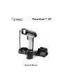
PowerScan™ RF
Systems Manual
PSC Scanning, Inc.
959 Terry Street
Eugene, Oregon 97402
Telephone: (541) 683-5700
Telefax: (541) 345-7140
PSC, the PSC logo, Quadralogic and PowerScan are registered trademarks of PSC Inc. All
other trademarks and trade names referred to herein are property of their respective owners.
All rights reserved. No part of the contents of this documentation or the procedures described
therein may be reproduced or transmitted in any form or by any means without prior written
permission of PSC Inc. Owners of PSC Inc.'s products are hereby granted non-exclusive,
revocable license to reproduce and transmit this documentation for the purchaser's own internal business purposes. Purchaser shall not remove or alter any proprietary notices, including
copyright notices, contained on this documentation and shall ensure that all notices appear on
any reproductions of the documentation.
Should future revisions of this manual be published, you can acquire printed versions by contacting PSC Customer Administration. Electronic versions will either be downloadable from the
PSC web site (www.pscnet.com) or provided on appropriate media. If you visit our web site
and would like to make comments or suggestions about this or other PSC publications, please
let us know via the “Contact PSC” page.
Disclaimer
Reasonable measures have been taken to ensure that the information included in this
manual is complete and accurate. However, PSC reserves the right to change any
specification at any time without prior notice.
TABLE OF CONTENTS
Introduction................................................................................................................................1
About This Manual ..................................................................................................1
References ..............................................................................................................1
Product Description .................................................................................................2
Laser Cautions ..............................................................................................................4
Radio Frequency Interference .......................................................................................5
Quick Start Instructions ............................................................................................................6
Unpacking and Inspecting the Base Station ...........................................................6
Installation Procedures ...........................................................................................6
Installing the Battery ......................................................................................................7
Verifying Scanner Operation .........................................................................................8
Connecting the Base Station to the Host Terminal ........................................................8
Linking the Scanner to a Base Station ........................................................................10
Verifying Scanner-to-Base Station Communications ............................................11
Using the PowerScan RF System ..........................................................................................11
Battery Charging and Maintenance .............................................................................12
Tips for Extending Battery Life ..............................................................................13
Disposing of Batteries ...........................................................................................13
Four Station Charger ............................................................................................13
How to Scan ................................................................................................................15
Depth of Field ........................................................................................................16
Active Symbologies ...............................................................................................20
Enhanced Scanning for Hard-to-Read Bar Codes ................................................20
LED and Beeper Indications ........................................................................................21
Maximizing Signal Range ............................................................................................25
Three-Position Lock ..............................................................................................26
Mounting the Base Station .....................................................................................................27
Horizontal (Table or Countertop) Mounting ...........................................................27
Vertical (Wall) Mounting ........................................................................................29
Post or Forklift Mounting .......................................................................................30
RF Programmable Features....................................................................................................31
Programming Overview ........................................................................................32
What Is Programming Mode? ...............................................................................33
The Programming Session ...................................................................................34
Programming Sequence .......................................................................................36
Systems Manual
i
Scanner vs. Base Station Features ...................................................................... 38
Interface (I/F) Selection ........................................................................................ 39
Universal Keyboard Wedge I/F Selection ............................................................. 42
Terminal/Keyboard Settings ................................................................................. 43
RF Beeper Settings .............................................................................................. 44
RF When to Beep ................................................................................................. 45
RF When to Beep Options (continued) ................................................................. 46
Radio Transmit Power .......................................................................................... 50
RF Channel Selection ........................................................................................... 51
Transmission Retries Before Message Time-out ................................................. 53
Wait Time for ACK ................................................................................................ 56
Wait Time For Scanner Power Shutdown ............................................................ 57
Wait Time Between Retries of Failed Transmission ............................................. 58
HACK Transmit Options ....................................................................................... 60
Wait Time For HACK From Host .......................................................................... 62
Drop Links on Reset Option ................................................................................. 63
Drop Oldest Links Option ..................................................................................... 64
Common Configuration ......................................................................................... 65
Set Maximum Linked Scanners ............................................................................ 67
Source-Radio Identification (ID) ........................................................................... 69
Low Battery LED Indication .................................................................................. 71
Maintenance and Troubleshooting........................................................................................ 72
Scanner Maintenance ........................................................................................... 72
Base Station Maintenance .................................................................................... 72
Four Station Charger Maintenance ...................................................................... 72
Troubleshooting .......................................................................................................... 73
If the Scanner Fails to Link with the Base Station ................................................ 74
Standard Warranty .................................................................................................................. 78
Exclusions ................................................................................................................... 78
Limitations of Liability .................................................................................................. 78
Assignment ................................................................................................................. 78
Risk of Loss ................................................................................................................. 78
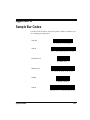
Appendix A: Sample Bar Codes ......................................................................................... A-1
Appendix B: Number Pad .................................................................................................... B-1
ii
PowerScan™ RF Scanner
Introduction
About This This systems manual provides information and instructions to connect
Manual and configure your PowerScan™ RF system. The following sections are
included in the manual:
•
Introduction presents general information about the contents of
this manual and about the system.
•
Quick Start Instructions provide easy to follow procedures for
installing your system quickly.
•
Using the PowerScan RF System provides details about scanning
basics, system controls and indicators.
•
Mounting the Base Station demonstrates ways to securely attach
the Base Station to various work surfaces.
•
RF Programmable Features is a set of procedures detailing system configuration that is unique to the RF system.
•
Maintenance and Troubleshooting provides solutions for problems that may be encountered during installation and use of
the system.
•
Standard Warranty is a statement describing the warranty policy covering the system.
References Other manuals are available for this product. Printed copies can be
ordered through your distributor. Some manuals can be downloaded
at our website address listed on the back cover of this manual. Read the
terms of use and instructions at the site to download, save, view or
print the most current manual(s) from the internet.
Configurator Express™ On-Screen Programming offers a convenient way
to program your scanner using your PC. Information about ordering a
kit (includes software, adapter and cable) for your RF scanner can also
be accessed from our website (see the back cover of this manual).
Systems Manual
1
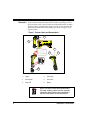
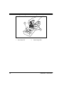
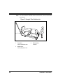
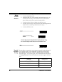
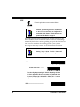
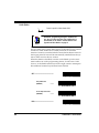
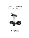
Product The PowerScan™ RF scanner is designed for durability, with high
Description impact-resistant material and protective rubber cushioning at every
point of impact, and it also provides the unleashed freedom of Radio
Frequency (RF) communication with your host system. Scanner and
Base Station nomenclature and labeling are shown in Figure 1 and
Figure 2 below.
Figure 1. Scanner Labels and Nomenclature
2
RF
1
COVERED
BY ONE OR MORE OF THE
FOLLOWING PATENTS:
4,387,297 • 4,409,470 • 4,460,120
4,593,186 • 4,652,750 • 4,673,805
4,736,095 • 4,816,660 • 4,845,350
4,861,972 • 4,866,257 • 4,879,456
5,179,270 • 5,180,904 • 5,237,161
5,247,161 • 5,247,162 • 5,258,604
5,260,554 • 5,298,728 • 5,311,000
5,330,370 • 5,468,949 • 5,475,206
5,481,098
Other patents pending
4
3
5
CAUTION—LASER RADIATION WHEN OPEN. AVOID EXPOSURE TO BEAM.
6
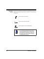
1.
Trigger
4.
Tether Hook
2.
Scan Window
5.
Yellow LED
3.
Green LED
6.
Battery
NOTE
2
Figure 1 and Figure 2 show label placement ONLY.
For actual regulatory, patent and other applicable
information, view the labels on the product itself, or
call your nearest sales or service representative.
PowerScan™ RF Scanner
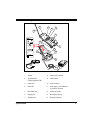
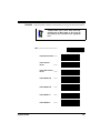
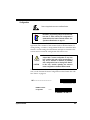
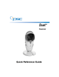
Figure 2. Base Station Labels and Nomenclature
2
3
5
4
1
6
E ID
PSC INC.
959 Terry Street
Eugene, OR 97402 U.S.A.
ACN
N263
C
BAS
X
TX/R GE
R
CHA WER
PO
US
LISTED
NWGQ 2Z78
14
This device complies with Part 15 of the FCC Rules.
Operation is subject to the following two conditions:
1. This device may not cause harmful interference.
2. This device must accept any interference, including
interference that may cause undesired operation.
7
Applicable patents are listed on label inside handheld unit.
8
FCC ID: O9NPWRSCAN-BS
CANADA38621032367A
13
9
MODEL: PowerScan RF Base Station
CLASS No.
SERIAL No.
FREQ:
Use ONLY PSC
AC/DC Power Supply
Input: +7.5V to +14V
Power: 5.5 Watts (max)
10
b
12
a
11
1.
Antenna
8.
Interface (I/F) Connector
2.
Transmit/Receive
(TX/RX)/ Diagnostics LED
9.
Cable Retainer
3.
Charge LED
10
Power Connector
4.
Power LED
11.
Power Supply - (a) AC Adapter or
(b) Forklift DC Converter
5.
Base ID Bar Code
12.
Interface (I/F) Cable
6.
Charging Pins
13.
Mounting Key Slots (3)
7.
3-Position Lock
14.
Mounting Flanges (4)
Systems Manual
3
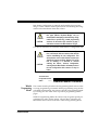
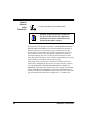
Laser Cautions
The PowerScan RF bar code scanner is certified in the U.S. to conform
to the requirements of DHHS/CDRH 21CFR Subchapter J for Class II laser
products (SR and LR) and Class IIIa (XLR). Class II and IIIa products are
not considered to be hazardous. The scanner contains a Visible Laser
Diode (VLD) at a wavelength of 650-670 nanometers and is designed so
that there can be no human access to harmful levels of laser light during normal operation, user maintenance, or during prescribed service
operations.
CAUTION
CAUTION
In the unlikely event that a bright laser spot is experienced rather than a scan line, do not stare into the
beam or attempt to repair the unit. Discontinue
operation and return the unit to your dealer. Note
that when using Marker Beam Mode, a single aiming
dot is projected momentarily preceding a scan line
and is not considered a malfunction.
Do not open or otherwise service any components
in the optics cavity. Opening or servicing any part
of the optics cavity by unauthorized personnel may
violate laser safety regulations. The optics system
is a factory only repair item.
The PowerScan™ RF scanner is required to be
used in conjunction with the PSC Base Station,
Model: PowerScan RF Base Station.
NOTE
4
PowerScan™ RF Scanner
Radio Frequency Interference
This device complies with Part 15 of the FCC Rules. Operation is subject to the following two conditions:
1.
This device may not cause harmful interference, and
2.
This device must accept any interference received, including
interference that may cause undesired operation.
This Class A digital apparatus complies with Canadian ICES-003.
Cet appareil numérique de la classe A est conforme à la norme NMB003 du Canada.
This equipment has been tested and found to comply with the limits
for a Class B digital device, pursuant to Part 15 of the FCC Rules. These
limits are designed to provide reasonable protection against harmful
interference in a residential installation. This equipment generates,
uses and can radiate radio frequency energy and, if not installed and
used in accordance with these instructions, may cause harmful interference to radio communications. However, there is no guarantee that
interference will not occur in a particular installation. If this equipment
does cause harmful interference to radio or television reception, which
can be dertermined by turning the equipment off and on, the user is
encouraged to try to correct the interference by one or more of the following measures:
Systems Manual
•
Reorient or relocate the receiving antenna.
•
Increase the separation between the equipment and receiver.
•
Connect the equipment into an outlet on a circuit different
from that to which the receiver is connected.
•
Consult the dealer or an experienced radio/TV technician for
help.
5
Quick Start Instructions
Unpacking and After unpacking your new Base Station, check the contents of the shipInspecting the ping carton to ensure all the items you ordered are included:
Base Station
• PowerScan™ Scanner Base Station
•
Interface Cable
•
Power Supply (AC Adapter or Forklift DC Converter)
•
Systems Manual (this manual)
•
Programming Guide
•
Optional Accessories that you ordered. (The Base Station can
be purchased with or without accessory kits.)
If your package contains wrong or missing components, contact your
place of purchase. If there are damaged components, immediately file a
claim with the carrier. You may want to save your packing material in
case you need to ship the scanner at some later time.
Other manuals for this product are available on our
internet website. See the back cover for our internet
address.
NOTE
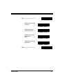
Installation The basic steps below must be performed to set up the RF scanner.
Procedures Each of these steps is detailed in this section.
6
•
Installing the Battery
•
Verifying Scanner Operation
•
Connecting the Base Station to the Host Terminal
•
Linking the Scanner to a Base Station
•
Verifying Scanner-to-Base Station Communications
•
Using the PowerScan RF System
PowerScan™ RF Scanner
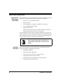
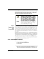
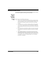
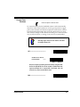
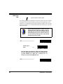
Installing the Battery
To assure maximum usage, batteries should always
be fully charged before their initial use. (See Battery
Charging and Maintenance on page 12.)
NOTE
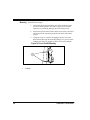
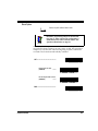
Orient the battery as shown in Figure 3, then push it into the scanner
until it snaps in place. To remove the battery, push in on the release tabs
on both sides of the battery’s base and pull it straight out of the scanner.
Figure 3. Installing the Battery
1
1.
Systems Manual
1
Battery Release Tabs
7
Verifying Scanner Operation
Once a charged battery has been installed in the scanner, scan the sample bar codes in Appendix A that correspond to the symbologies your
scanner is programmed to read. If unsure how to do this, see the section on How to Scan in this manual. The system may signal with one or
a combination of indicators depending upon how the scanner and Base
Station are programmed to respond (see LED and Beeper Indications for
details). If your scanner fails to read a sample bar code of a symbology
it’s programmed to read, turn to the section titled, Maintenance and
Troubleshooting.
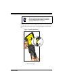
Connecting the Base Station to the Host Terminal
NOTE
1.
It is important that the interface (I/F) cable be connected to the Base Station prior to applying power
to the system. This is because the interface type
(RS-232, IBM, Keyboard Wedge, etc.) is selected by
the Base Station subject to the I/F cable it is connected to at the time of power-up.
Connect the I/F cable to the Base Station (see Figure 4A). The
I/F cable is inserted into the connector and the cable retainer
clip is rotated over the cable overmold until the retainer snaps
in place (see Figure 4B). To disconnect the cable, push in on the
retainer (away from the catch on the plastic wall) to release it
and enable it to swing upward, allowing the cable to be pulled
free (see Figure 4C).
Figure 4. Connecting/Disconnecting the Interface (I/F) Cable
a
b
c
8
PowerScan™ RF Scanner
2.
Consult your Host Terminal manual to determine the required
communication parameters for the Host Terminal (e.g., baud
rate, parity, etc.) and, if necessary, modify the programmed
parameters to be compatible with those requirements. Scanner
and Base Station programming is performed using one of the
following:
- Configurator Express™ Programming Software
- PowerScan™ Bar Code Scanner Programming Guide
See References for more information about how to
obtain software and manuals for this product.
NOTE
CAUTION
Systems Manual
The Host Terminal manual should also be consulted
as to whether power must be turned off before connecting peripheral devices. Ensure that the correct
procedure is followed to avoid damage to equipment or interruption of system functions.
3.
Connect the I/F cable to the proper port on the Host Terminal
(check your Host Terminal manual to determine hardware
requirements).
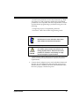
4.
Connect the AC Adapter's power cord at the Base Station and
plug the AC/DC adapter in at the wall outlet (see Figure 5).
The Base Station’s POWER LED should be illuminated when
the unit is properly connected to power.
9
Figure 5. Connecting Power to the Base Station
5.
Apply power to the Host Terminal.
6.
Verify communication with the Host Terminal by aiming the
linked scanner at a sample bar code from Appendix A, and
pulling the trigger (see How to Scan for tips about scanning bar
codes). Confirm that the scanner/Base Station sent the data to
the host terminal. If not, see the section, Maintenance and Troubleshooting. Once all communications are verified, the system is
ready for use.
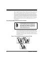
Linking the Scanner to a Base Station
To link a scanner to a Base Station, simply scan the Base Station ID bar
code located on the top of the desired Base Station (see Figure 2). As the
scanner searches for the Base Station, a short beep is heard as it seeks
for the correct channel. When the Base Station responds to the request,
the scanner’s beeper will either sound a "Link Granted," or "Link
Denied" signal (see the section, LED and Beeper Indications for more
information).
10
PowerScan™ RF Scanner
The existing Base Station system configuration can be automatically
downloaded to the scanner. This automatic download feature is configurable and can be disabled. See the section, Common Configuration for
more information about this feature. If downloading occurs, a slight
delay with link verification announcement will occur.
CAUTION
Verifying
Scanner-to-Base
Station
Communications
Since a new/replacement scanner may have been
shipped with a custom configuration or may have
been modified with other special programming, it
may not be desirable to download a potentially
older configuration from an existing Base Station.
In this case, reference the RF Programmable Features section of this manual, or the Configurator
Express™ On Screen Programming Software and
consider uploading the scanner’s newer configuration to the Base Station prior to linking.
Point the linked scanner at a sample bar code from Appendix A, and
pull the trigger (see How to Scan for tips on scanning bar codes). Watch
the TX/RX (transmit/receive) indicator LED on the Base Station and/
or scanner green LED while scanning the bar code. The LEDs should
flash momentarily as the two devices communicate. If no communication is indicated, see the section titled, If the Scanner Fails to Link with the
Base Station.
When the scanner is programmed to do so, communication can also be
indicated by a second "acknowledgement" tone 1 that is sounded after a
"good read" tone. If a transmission error beep (warble) is heard following a "good read" tone instead of the single acknowledgement tone,
communication between the devices may have failed2. Refer to the sections Using the PowerScan RF System, and Maintenance and Troubleshooting for possible remedies, should this occur.
Using the PowerScan RF System
This section covers the following topics:
•
Battery Charging and Maintenance
•
How to Scan
1. See LED and Beeper Indications for more details about beeper signals.
2. Other reasons for a "warble" are that the Base Station may be configured differently than the scanner, or that the system’s interface doesn’t support the symbology (bar code type) you’re trying to
scan.
Systems Manual
11
•
LED and Beeper Indications
•
Maximizing Signal Range
•
Three-Position Lock
Battery Charging and Maintenance
NOTE
When the scanner is in use, a low battery condition
is indicated by a repeated two-flash signal from the
scanner’s green LED every time the trigger is pulled
before the laser is enabled. This indicator may have
been disabled via custom programming. See LED
and Beeper Indications for more information.
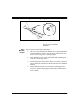
Seat the scanner in the Base Station as shown in Figure 6, ensuring that
the battery fully engages the station’s metal contacts. The CHARGE
LED on the Base Station should flash, indicating the battery is charging.
Figure 6. Charging the Battery
Rapid flashing indicates that charging is taking place. Rapid charging
occurs when the battery temperature is between 10°C (50°F) and 46°C
(115°F), and/or voltage of the battery is between 2.0 and 3.2V. Charge
time is less than 4.2 hours. Rapid charge ends with the battery at
approximately 90 to 95% capacity. The CHARGE LED remains on
steady when trickle charging or after the charge cycle is complete.
A scanner may be charged simultaneously while
other scanners are in use with the Base Station.
NOTE
12
PowerScan™ RF Scanner
NOTE
Batteries will not charge if their temperature is
below 0°C (30°F). If a battery that is too cold is
inserted into the Base Station, the Charge LED will
not illuminate.
Tips for Nickel Metal Hydride (NiMH) batteries will better hold a charge if
Extending allowed to discharge at least once a week. The chemical reactions that
Battery Life correspond to charge and discharge in a rechargeable battery should
occur to obtain the maximum number of charge/discharge cycles in
the battery. If a battery is removed from the scanner and stored, it
should be fully charged when stored. Batteries will lose the ability to
hold a charge when stored for long periods of time (weeks, months, or
longer).
Batteries will typically have about 30% charge capacity when shipped.
To assure maximum usage, the battery should be fully charged before
use.
Store your battery in a cool dry place. Do not leave your battery
exposed to direct sunlight or temperatures below 0°C (30°F) and above
38°C (100°F).
Disposing of There presently are no US, North America or World disposal requireBatteries ments for NiMH batteries, so when they won't hold a charge anymore,
the batteries can be disposed of, preferably through a recycling center.
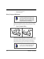
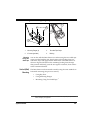
Four Station If you have a Four Station Charger, batteries are inserted for charging
Charger as shown in Figure 7. A 90% rapid charge can be achieved in only two
hours when using this optional accessory; half the time than when a
Base Station is used for charging. The LEDs at each battery station
operate the same as the CHARGE LED on the Base Station, with rapid
flashing indicating that rapid charging is taking place and on steady
during trickle charging or when the rapid charge cycle is finished.
NOTE
Systems Manual
If you insert a battery into the Four Station Charger
and no LEDs illuminate, the battery may be too
cold. Batteries must be at 0°C or higher to charge.
Do not attempt to charge cold batteries, since placing them in the charger will curtail the charging of
other batteries already present in the unit.
13
Figure 7. Using the Four Station Charger Accessory
1
2
1.
14
Device Power LED
2.
Station Charge LEDs
PowerScan™ RF Scanner
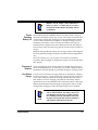
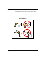
How to Scan
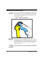
Figure 8 illustrates some tips to help get the best scanning results:
1.
The scanner must be pointed at a slight angle to the bar code.
Do not hold the scanner perpendicular to the bar code.
2.
The laser beam must cross the entire bar code. The scanner
cannot correctly read if the entire bar code is not scanned.
Figure 8. Scanning Tips
1
1
2
2
Systems Manual
15
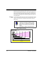
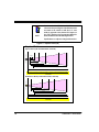
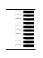
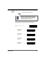
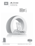
Depth of Field There are currently four different range models for the RF scanner.
Depending upon the model type of your scanner, you’ll need to hold
the unit at a given distance from the bar code to achieve optimum scanning results. The following diagrams provide depth of field information for each of the models when scanning grade A, Code 39 bar codes:
Standard Range (SR), High Density (HD), Long Range (LR) and Extra
Long Range (XLR).
Definition of
a "mil"
A "mil" is equal to 0.001 inches. In the context of the illustrations in this
section, a mil represents the minimum bar code element width. Thus a
5 mil bar code would have a minimum element width of 5 mils (or
0.005 inches).
Measurements are based on SR models set with the
standard 28° scan width (as opposed to the Half
Angle setting of 14°). Reference the Programming
Manual for more information about the Half Angle
feature.
NOTE
Specifications are subject to change without notice.
Figure 9. Depth of Field (SR)
Depth of Field
Paper Labels (SR decoded model, Code 39)
FRONT OF SCANNER
5 mil
7.5 mil
10 mil
15 mil
20 mil
40 mil
55 mil
1
0
16
10
20
30
2
40
50
60
3
FEET
70
80
90 100
CENTIMETERS
4
110
120
5
130
140
150
160
170
PowerScan™ RF Scanner
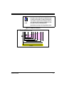
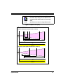
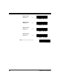
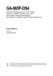
See the section titled, Definition of a "mil" for more
information about reading this chart. Measurements
are based on HD models set with the standard 28°
scan width (as opposed to the Half Angle setting of
14°). Reference the Programming Manual for more
information about the Half Angle feature.
NOTE
Specifications are subject to change without notice.
Figure 10. Depth of Field (HD)
Depth of Field
FRONT OF SCANNER
Paper Labels (HD decoded model, Code 39)
3 mil
4 mil
5 mil
7.5 mil
10 mil
20 mil
1
0
Systems Manual
2
5
3
INCHES
4
10
CENTIMETERS
5
6
15
7
8
20
17
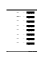
See the section titled, Definition of a "mil" for more
information about reading this chart. Measurements
are based on LR models set with the a 14° scan
width (as opposed to the alternate Full Angle setting of 28°). Reference the Programming Manual for
more information about the Half Angle feature.
NOTE
Specifications are subject to change without notice.
Figure 11. Depth of Field (LR)
Depth of Field
FRONT OF SCANNER
Paper Labels (LR decoded model, Code 39)
7.5 mil
10 mil
15 mil
20 mil
40 mil
55 mil
1
0
10
20
30
2
40 50
3
60 70
4
5
FEET
6
7
8
9
80 90 100 110 120 130 140 150 160 170 180 190 200 210 220 230 240 250 260 270 280
CENTIMETERS
FRONT OF SCANNER
Reflective Labels (LR decoded model, Code 39)
40 mil
55 mil
70 mil
100 mil
1
2
3
4
5
6
7
8
9
10
11
12 13
FEET
14
15
16
17
18
19
20
21
22
0 10 30 50 70 90 110 130 150 170 190 210 230 250 270 290 310 330 350 370 390 410 430 450 470 490 510 530 550 570 590 610 630 650 670
CENTIMETERS
18
PowerScan™ RF Scanner
See the section titled, Definition of a "mil" for more
information about reading this chart. Measurements
are based on XLR models set with a 10° scan angle
width.
NOTE
Specifications are subject to change without notice.
Figure 12. Depth of Field (XLR)
Depth of Field
FRONT OF SCANNER
Paper Labels (XLR decoded model, Code 39)
15 mil
20 mil
40 mil
55 mil
1
0
2
3
50
4
100
5
6
150
7
200
8
FEET
9
250
CENTIMETERS
10
11
300
12
13
350
400
14
15
450
FRONT OF SCANNER
Reflective Labels (XLR decoded model, Code 39)
40 mil
70 mil
100 mil
1 2 3 4 5 6 7 8 9 10 11 12 13 14 15 16 17 18 19 20 21 22 23 24 25 26 27 28 29 30 31 32 33 34 35 36
FEET
0
Systems Manual
50
100
150
200
250
300
350
400
450
500 550 600 650 700
CENTIMETERS
750
800
850
900
950 1000 1050 1100
19
Active The active (enabled) bar code symbologies in the standard factory
Symbologies defaults are:
•
Code 39 (C39)
•
Code 128 (C128)
•
Interleaved 2 of 5 (I 2 of 5)
Your scanner should be pre-programmed with these standard factory
default settings, unless...
...it was shipped to you programmed with unique, customer configuration settings.
...you or another user have made changes to scanner programming.
Enhanced
Scanning for
Hard-to-Read
Bar Codes
Decoded scanners can be programmed to decode extremely poor quality bar codes by activating advanced Quadralogic™ Decoding. To
select this feature, see the Programming Guide.
Scanner programming can also be performed using your PC and the
Configurator Express™ On-Screen Programming Kit.
Information about manuals, kits and programming
software for this product are available at our website. See the back cover for our web address.
NOTE
20
PowerScan™ RF Scanner
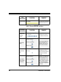
LED and Beeper Indications
The Base Station LED indicators and the scanner’s LEDs and beeper are
used to announce system status and perform other useful signals. The
tables below list the default function of each of the various indicators.
Some LED and beeper indications can be disabled
or modified via scanner programming. The tables
indicate the default behavior of the indicators, with
shaded rows representing features that are programmable.
NOTE
Table 1. Scanner GREEN LED Functions
LED
INDICATION
COMMENT
Disable
Indication
100ms on, 900 ms off
Indicates the scanner has
been disabled.
Good Read
Indication
500 ms on
Indicates a bar code has
been read and decoded.
Program Mode
Indication
Field Replaceable Unit (FRU)
Indications
Low Battery
Indication
Systems Manual
DURATION
500 ms on, 500 ms off
Continuous flashing
Indicates the scanner is in
Programming Mode.
Varies. Consists of a long
flash followed by multiple short
flashes.
Enables service technicians to identify Field
Replaceable Unit (FRU)
errors.
Two flashes at 100 ms on, 350
ms off.
Occurs at trigger pull
before the laser is enabled.
Indicates the battery is in
need of recharging.
21
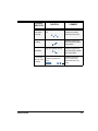
Table 2. Scanner YELLOW LED Functions
LED
INDICATION
Laser on indication
DURATION
On Steady
COMMENT
The yellow LED illuminates
whenever the laser is on.
Table 3. Scanner BEEPER Functions
SPEAKER
INDICATION
Scanner Not
Currently
Linked
DURATION
Six beeps consisting of 20 ms
on, 20 ms off
COMMENT
Indicates a bar code was
read before the scanner
was linked to a Base Station.
100 ms on (short)
Good Read
Beep
250 ms on (medium)
500 ms on (long)
Partial Read
Bip
20 ms on
100 ms on (short)
Base Station
Acknowledgement Beep
22
250 ms on (medium)
500 ms on (long)
Three programmable functions are available. This
indicates a bar code has
been read and decoded.
A very short beep ("bip") is
sounded when one bar
code of a two-bar code pair
has been successfully
decoded.
Indicates a successful bar
code transmission to the
host (configurable), a successful change of channel,
or a successful transmission of a new configuration
to the host.
PowerScan™ RF Scanner
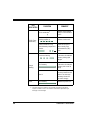
SPEAKER
INDICATION
Transmission
Error Beep
DURATION
High, then low, then high, then
low.
Indicates a scanner has
been successfully linked to
a base station.
High, then medium, then low.
Indicates a scanner has
been successfully unlinked
from a base station.
Varies. Consists of a long tone
followed by multiple short
tones.
Enables service technicians to identify Field
Replaceable Unit (FRU)
errors.
Unlink Beep
Systems Manual
Indicates unsuccessful
transmission to the host.
Low, then medium, then high.
Link Beep
Field Replaceable Unit (FRU)
Indications
COMMENT
23
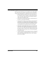
Table 4. Base Station LED Functions
LED
INDICATION
DURATION
Lit for variable timea
TX/RX (Transmit/Receive)
Continuous rapid
flashing at power-up
Varies. Consists of a long
flash followed by multiple short
flashes.
Continuous flashing
Charge
(Battery)
Power
COMMENT
Indicates communications
activity to or from the Base
Station.
Indicates a broken radio.
Enables service technicians to identify Field
Replaceable Unit (FRU)
errors.
When a scanner is nested
in the station, this indicates
its battery is being quick
charged.
Lit Constantly
When a scanner is nested
in the station, this indicates
its battery is at or near full
charge.
Not Lit
A scanner is not present or
incorrectly inserted into the
station. It can also mean
the battery is below 0°C
(too cold for charge)
Lit Constantly
Indicates that power is on.
a. The LED remains on while the unit is actively processing code which
requires a TX/RX to occur. The duration of the LED is dependent upon
the length of the message.
24
PowerScan™ RF Scanner
Maximizing Signal Range
Here are a few tips about how you can optimize your system installation to allow the scanner greater roving distance from its linked Base
Station while maintaining clear communication between the devices.
Systems Manual
•
Minimize obstructions between the scanner and its Base Station. While the system is capable of communicating through
walls, a clean line of sight will always increase the scanner’s
signal range from the Base Station.
•
Never place or install the Base Station in a metal-lined area or
enclosure, or near large metal objects.
•
Position the Base Station and experiment at various elevations,
orientations, etc. to achieve better communications between
devices. The system usually works best at heights of one meter
or more off the ground. Usually the scanner and Base Station
work optimally when operating at about the same height.
•
Ensure that programmable features are set to maximize radio
transmission. For example, if the feature Radio Transmit Power
is set to low, set it to high. Selecting a different channel using
the options under RF Channel Selection might also help. See the
section titled, RF Programmable Features, for more information
about these features.
•
Consider using a Four Station Charger accessory to charge batteries as opposed to using the Base Station for this function. It
offers faster charging (about half the time to a 90% charge as
Base Station charging).
25
Three-Position The Base Station is equipped with a three-position lock to allow a scanLock ner to be secured in the Base Station in horizontal, vertical, and forklift
installations.
Figure 13. Using the Three-Position Lock
1
2
3
26
1.
Top position:
Vertical Forklift Mount Lock
2.
Middle position:
Vertical (Wall) Mount Lock
3.
Bottom position:
Unlocked
PowerScan™ RF Scanner
Mounting the Base Station
The Base Station can be secured to varying surfaces to ensure a permanent, stable installation. Several options are available.
Horizontal
(Table or
Countertop)
Mounting
Using Key
Slots
Systems Manual
Refer to Figure 14 and follow these steps:
1.
Once you have identified the desired area for permanent Base
Station installation, use the mounting template included with
this manual to mark the position of its "key slot" mounting
screws.
2.
Install three #8 x 1" (4.1mm x 25.4mm) pan head, self-tapping
screws in the marked positions until completely threaded into
the mounting surface, then back the screws off two to three full
turns.
3.
Ensure that power and interface cables are securely connected
and routed in the channels provided in the bottom of the Base
Station.
4.
Align the Base Station key slots (wide end) with the screws,
then slide the Base Station to position the screws in the smaller
ends of the key slots. Adjust the height of the mounting screws
if needed for a secure fit. The Base Station is now secured to
the table or countertop.
27
Figure 14. Mounting Using Key Slots
2
1
BASE
ID
X
TX/R GE
CHAR WER
PO
1.
Key Slots
Using
Mounting
Flanges
28
2.
#8 x 1" (4.1mm x 25.4mm) Pan
Head Screw
Refer to Figure 15a and follow these steps:
1.
Once you have identified the desired area for permanent Base
Station installation, hold the unit in place and mark the position of screws using the "mounting flanges."
2.
Start and remove four screws (provided) at the marked positions in the mounting surface.
3.
Ensure that power and interface cables are securely connected
and routed in the channels provided in the bottom of the Base
Station.
4.
Secure the Base Station to the surface by installing the four
screws into the mounting flanges. Base Station attachment is
now complete.
PowerScan™ RF Scanner
Figure 15. Mounting Using Flanges or Two-sided Tape
4
2
3
BASE
ID
X
TX/R GE
CHAR WER
PO
1
a
b
1.
Mounting Flanges (4)
3.
Two-sided Tape Strips
2.
4 Screws (provided)
4.
Backing
Mounting
Using TwoSided Tape
You can also affix the Base Station to a surface using the two-sided tape
strips provided with the unit. Simply remove the backing from one
side of the strips and apply them to the bottom of the Base Station as
shown in Figure 15b. Remove the remaining backing from the tape,
then position and firmly press the unit against a smooth, clean surface
in the orientation desired.
Vertical (Wall) The Base Station can be mounted vertically using the same methods as
Mounting horizontal mounting (see previous section):
•
Using Key Slots
•
Using Mounting Flanges
•
Mounting Using Two-Sided Tape 1
1. Since mounting using this method offers less secure attachment, verify that your tape installation
is robust enough for your application.
Systems Manual
29
Post or Forklift To secure the Base Station to a post or forklift frame, refer to Figure 16
Mounting and follow these steps:
1.
Verify that the desired mounting area offers sufficient space
for safe forklift operation and will not present a hazard for
operators or potentially damage the mounted device(s).
2.
Ensure that power and interface cables are securely connected
and routed in the channels provided in the back of the Base
Station.
3.
Using tie-wraps or a similar strapping material, secure the
Base Station (through the mounting flanges) to a post or frame.
Tighten and adjust as needed to assure a secure installation.
Figure 16. Post or Forklift Mounting
1
1.
30
Tie Wraps
PowerScan™ RF Scanner
RF Programmable Features
Use the special programming bar codes contained in this section to set
features that are unique to RF models of PowerScan™ bar code scanners. To program other features that are common to all models, use one
of the following:
- Configurator Express™ On-Screen Programming Kit
- PowerScan™ Programming Guide
See References on page 1 for more information
about how to obtain kits, software and manuals for
this product.
NOTE
Programming features included in this manual are:
Systems Manual
•
Interface (I/F) Selection
•
RF Beeper Settings
•
Radio Transmit Power
•
RF Channel Selection
•
Transmission Retries Before Message Time-out
•
Wait Time for ACK
•
Wait Time For Scanner Power Shutdown
•
Wait Time Between Retries of Failed Transmission
•
HACK Transmit Options
•
Wait Time For HACK From Host
•
Drop Links on Reset Option
•
Drop Oldest Links Option
•
Common Configuration
•
Set Maximum Linked Scanners
•
Source-Radio Identification (ID)
•
Low Battery LED Indication
31
Programming The RF system's programmable feature settings can be modified to
Overview accommodate your unique requirements. Listed below are the various
methods to configure scanner and Base Station units:
Base Stations and the scanners linked to them must
possess compatible configuration files.
NOTE
Scanner
1.
The Base Station’s configuration files can be automatically
downloaded to the scanner at the time of linking. See the sections, Linking the Scanner to a Base Station and Common Configuration for more details.
2.
The easiest, most comprehensive way to program the scanner
is to use the Configurator Express™ On-Screen Programming
Kit. See References for more information about this product.
3.
The scanner can be configured using special programming bar
codes like those contained in this section. For the most part, the
programming instructions and bar codes on the following
pages address this method of scanner configuration.
If you program the scanner using any of the
methods above, the scanner will store the changes
until reprogrammed or returned to factory defaults.
NOTE
32
PowerScan™ RF Scanner
Base Station
Base Station configuration is primarily performed by first programming a scanner with the desired options, then downloading the configuration to the Base Station from that scanner.
CAUTION
Verify that the scanner and Base Station host interface types (RS-232, Keyboard Wedge, etc.) are
matched before attempting to download any configuration files or perform any custom programming
sessions. Go to Interface (I/F) selection on page x
and set the scanner to the Base Station’s I/F type.
Use the bar code below to overwrite a Base Station’s configuration file.
CAUTION
After the Base Station receives the entire configuration, it will drop all links to scanners other than the
scanner transmitting the new configuration. This
will require the user to relink all other scanners (see
Linking the Scanner to a Base Station). Prior to the
time of relinking, it is advisable to consider
enabling the feature, Common Configuration,
ensuring that the Base Station will attempt to share
the new configuration with scanners as they are
linked.
Transmit Scanner
Configuration to Base
Station
---------
What Is The scanner must be placed into the Programming Mode state in order
Programming to accept programming commands. When programming using the bar
Mode? code labels in this manual, the scanner is placed in Programming Mode
by scanning the "SET" label at the top of most programming feature
pages.
While in Programming Mode, the scanner only recognizes special programming bar codes. See the section, LED and Beeper Indications for
information about scanner indications while in Programming Mode.
Systems Manual
33
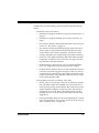
The Scanner programming allows you to customize the scanner’s configuProgramming ration to match your specific needs. A typical programming session is
Session conducted as follows:
1.
Scan the SET bar code at the top of the page. The scanner will
emit one beep, indicating it has read the bar code and the green
LED will flash on and off slowly while the scanner remains in
Programming Mode. Normal scanning functions are disabled.
2.
Scan the programming bar codes(s) to make the desired
changes. With few exceptions, the scanner will emit a triple
beep each time you scan a valid programming bar code..
NOTE
NOTE
3.
Not all features are available for all interfaces. The
scanner will sound an error tone when scanning
programming bar codes for features that cannot be
used with the currently active interface. Only features supported by the currently active interface
will be implemented.
If you are enabling a different interface (I/F), we suggest/recommend that you change the I/F designation first and then proceed with other changes.
Once a bar code is scanned that changes the scanner's I/F, all previous I/F configuration items
scanned in the programming session are lost.
Scan the END label at the bottom of the page to save any new
settings and exit Programming Mode. The scanner will sound
a beep and reset upon exiting Programming Mode, and the
green LED will return to its usual state (on steady or off).
The scanner will not exit Programming Mode unless the END
bar code is scanned or the scanner’s battery is removed.
Removing power during Programming Mode, before scanning
the END label, will cause all new settings to be ignored. On
power-up, the scanner will return to previous settings.
34
PowerScan™ RF Scanner
4.
Systems Manual
Maintain a record of all changes made to ensure that you
know if the original factory settings have been changed. Use
the following table to log your custom configuration changes.
RF
Programmable
Feature
Factory
Default
Setting
RF When to Beep
Option 7
RF Beeper Volume
Vol 3
RF Beeper Frequency
High
RF Beep Duration
50ms
Radio Transmit Power
High
RF Channel Selection
Channel 1
Transmission Retries
Before Message Timeout
3 Retries
Wait Time for ACK
200ms
Wait Time for Scanner
Power Shutdown
1 Second
Wait Time Between
Retries of Failed Transmission
90ms
HACK Transmit Options
HACK upon
Base Station
transmission to
host
Wait Time for HACK
From Host
1 Second
Drop Links on Reset
Option
Disable
Drop Oldest Links
Option
Enable
Your
Setting
Comment
35
Common Configuration
Disable
Set Maximum Linked
Scanners
8
Source-Radio Identification (ID)
Don’t Include
Low Battery LED Indication
Enable
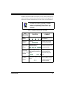
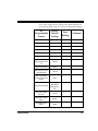
Programming To modify a scanner feature (item), the programming bar codes conSequence tained in this manual must be scanned in a given sequence depending
upon the feature being programmed (as shown in Table 5). There are
three possible programming sequences:
A. Programming sample A (the most commonly used format)
demonstrates how three bar codes are scanned in sequence to
do the following:
1.
Place the scanner in Programming Mode (SET bar code).
2.
Scan the Item Tag1 that will enable the new feature.
3.
End the programming session and reset the scanner (END
bar code).
B. Sample B provides an example of a programming feature
requiring the entry of a range value. Like sample A, the scanner is placed in Programming Mode and an Item Tag 1 is
scanned. Then, a value must be entered before ending the programming session. In the example, three digits must be
scanned from the number pad in Appendix B. This type of format, requiring a total of as many as six programming bar
codes, is necessary to allow flexible programming with larger
item value numeric ranges.
C. The programming sequence shown in example C requires
scanning of a single, extended length bar code. This special
programming bar code contains all the data necessary to enter
Programming Mode, set the Item Tag1 and Item Value, and exit
Programming Mode (all in one step).
1. An “Item Tag” is a term used to describe an assigned number, which is encoded in a programming
bar code, that toggles (selects, enables, disables, etc.) a specific programming feature.
36
PowerScan™ RF Scanner
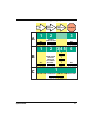
Table 5. Programming Sequence
SET
A
ITEM TAG
ITEM VALUE
END/RESET
1
2
3
SET
ENABLE
NEW FEATURE
END
1
2
345
6
0
B
SET
C
Systems Manual
ENABLE NEW
FEATURE
USING THE
FOLLOWING
SETTINGS...
0
8
END
1
ONE BAR CODE CONTAINS SET + ITEM TAG + ITEM VALUE + END
37
Scanner vs. Some programming features are specific to either the scanner (handBase Station held unit) or the Base Station, while others are applicable to both. Each
Features feature in this manual is marked with an indicator as to which unit(s) it
is applicable.
Feature is specific to scanner ONLY
Feature is specific to Base Station ONLY
Feature is applicable to scanner and Base Station.
NOTE
38
When programming using bar codes via the scanner, it is important to remember that features affecting the Base Station WILL NOT be enabled until the
new configuration is downloaded to the Base Station using the feature Transmit Scanner Configuration to Base Station on page 33.
PowerScan™ RF Scanner
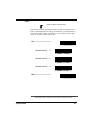
Interface (I/F) It is very important that the scanner and Base Station are each configSelection ured to operate with the same interface (I/F) type as the host terminal.
NOTE
The Base Station uses a “smart” cable, which automatically sets the Base Station to the correct I/F
upon power-up and connection to the appropriate
host.
SET -------------------------------------------
Enable Wand Emulation ---------
Enable Standard
RS-232
---------
Enable Wincor Nixdorf
RS-232
---------
Systems Manual
Enable IBM Port 5B
---------
Enable IBM Port 9B
---------
Enable IBM Port 17
---------
Enable IBM Port E
---------
39
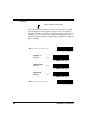
Enable Keyboard Wedge
--------Type Aa
Enable Keyboard Wedge
Type B
---------
Enable Keyboard Wedge
Type C
---------
Enable Keyboard Wedge
Type D
---------
Enable Keyboard Wedge
Type E
---------
Enable Keyboard Wedge
Type F
--------Enable Keyboard Wedge
Type G
---------
Enable Keyboard Wedge
Type H
---------
Enable Keyboard Wedge
Type I
--------Enable Keyboard Wedge
Type J
---------
END ------------------------------------------
a. See Table 6 for the specific interfaces supported by each of the keyboard
types listed above. See the following section Universal Wedge Terminal
Selection to enable that interface type.
40
PowerScan™ RF Scanner
Table 6. Keyboard Wedge I/F Selection
Systems Manual
I/F Type
PCs Supported
A
PC/XT w/Alternate Key Encoding
B
AT, PS/2 25-286, 30-286, 50, 50Z, 60, 70, 80, 90 & 95
w/Alternate Key Encoding
C
PS/2 25 and 30 w/Alternate Key Encoding
D
PC/XT w/Standard Key Encoding
E
AT, PS/2 25-286, 30-286, 50, 50Z, 60, 70, 80, 90 & 95
w/Standard Key Encoding
F
PS/2 25 and 30 w/Standard Key Encoding
G
IBM 3xxx w/122 keyboard
H
IBM 3xxx w/102 keyboard
I
PS/55 5530T w/104 keyboard
J
NEC 9801
41
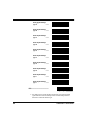
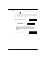
Universal To activate the Universal Wedge interface, follow these instructions:
Wedge
1. Scan the START bar code.
Terminal
2. Determine the I.D. of the terminal/keyboard. Refer to the TerSelection
minal/Keyboard Settings section below for more information
plus a listing of the most common keyboard I.D.s.
3.
Scan the Activate Universal Wedge Interface bar code.
4.
Use the Universal Wedge Number Pad to scan in the digits for the
keyboard I.D. number you determined in step 2.
5.
Scan the END bar code.
START----------------------------------------
Activate Universal Wedge
Interface
---------
Scan the digit(s) representing the desired keyboard I/F type using
the Universal Wedge Number Pad, then scan the END bar code.
END ------------------------------------------
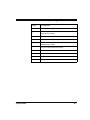
Terminal/ The list below contains the most common terminal/keyboard types. If
Keyboard your specific system is not listed below, consult the Universal KeySettings board Wedge Connectivity Guide for a detailed listing of terminal/
keyboard types. A copy of the guide can be obtained from the internet
at www.pscnet.com, or call your dealer for customer support information.
42
Keyboard
Terminal I.D.
High Speed PC/AT, PS2
591
PC AT, PS2
11
MAC
25
PowerScan™ RF Scanner
Universal The default communication mode (factory settings) is Keyboard Wedge
Wedge Number of PC AT (keyboard I.D. 11). Use the codes on this page to select the
Pad I. D. corresponding to your computer or terminal (reference the Universal Keyboard Wedge Connectivity Guide for this product or call
PSC Customer Support).
0 →
1 →
2 →
3 →
4 →
5 →
6 →
7 →
8 →
9 →
Systems Manual
43
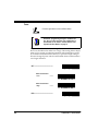
RF Beeper The RF version of the scanner exhibits different beeper behavior than
Settings standard (non-RF) models. For more information about RF beeper indications, see the section, LED and Beeper Indications.
NOTE
The following descriptions highlight configurable
beeper functions that are unique to RF handheld
scanners. All other beeper functions supported by
the standard version of the scanner are supported
by RF models.
Good Read Beep — When good read beep is enabled, this beep sounds
at the time the scanner successfully reads a bar code. Selectable settings
for the good read beep include:
•
RF When to Beep
•
Beeper Volume
•
Good Read Beep Frequency
•
Beep Duration
ACK Beep — The scanner can sound an acknowledgement (ACK)
beep to indicate when the Base Station has acknowledged to the scanner that is has received a successful data transmission from the scanner.
This beep is also sounded upon a successful channel change sequence
or a successful configuration transmission.
Transmission Error Beep — Another selectable indicator beep is the
transmission error beep. This beep sounds to indicate an error in transmission between the RF devices.
Link Beep — The handheld scanner will sound a special link beep
upon successfully linking with a Base Station. This indication cannot be
disabled and is not programmable, other than that it shares the same
Beeper Volume setting as other beeper indications set using that feature.
Unlink Beep — When a scanner is successfully unlinked from a Base
Station, a unique unlink beep is sounded. This beep is not programmable, and also sounds at the same volume set for Beeper Volume.
44
PowerScan™ RF Scanner
RF When to
Beep
Feature is specific to scanner ONLY
Several options are available to specify how the RF handheld scanner
will beep to indicate a good read. Settings are based on the enable/disable status desired for three selectable beep indications:
•
Good Read Beep
•
Acknowledgement (ACK) Beep
•
Transmission Error Beep
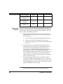
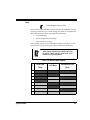
The available options are described and numbered in Table 7 to correspond with the programming bar codes provided for this feature.
These settings supersede any settings made using
the generic "When to Beep" feature listed in the
PowerScan Programming Manual.
NOTE
Table 7. RF When to Beep Options
Systems Manual
#
Good Read
Beep
ACK Beep
Transmission Error
Beep
0
Disabled
Disabled
Disabled
1
Disabled
Disabled
Enabled
2
Disabled
Enabled
Disabled
3
Disabled
Enabled
Enabled
4
Enabled
Disabled
Disabled
5
Enabled
Disabled
Enabled
6
Enabled
Enabled
Disabled
7
Enabled
Enabled
Enabled
45
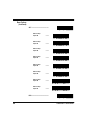
RF When to
Beep Options
(continued)
SET -------------------------------------------
When to Beep
Option #0
---------
When to Beep
Option #1
---------
When to Beep
Option #2
---------
When to Beep
Option #3
---------
When to Beep
Option #4
---------
When to Beep
Option #5
---------
When to Beep
Option #6
---------
When to Beep
Option #7
---------
END ------------------------------------------
46
PowerScan™ RF Scanner
RF Beeper
Volume
Feature is specific to scanner ONLY
The volume at which the beeper sounds for ACK, transmission error,
link, or unlink beeps (but not the good read beep1) are all affected by
this setting. Select volume #1 (25% duty cycle), volume #2 (35% duty
cycle), or volume #3 (50% duty cycle).
SET -------------------------------------------
RF Beeper Volume #1
---------
RF Beeper Volume #2
---------
RF Beeper Volume #3
---------
END ------------------------------------------
1. Good read beep volume is selectable via the features available in the PowerScan Programming
Manual (P/N R44-1840). See References for information about acquiring other manuals.
Systems Manual
47
RF Beeper
Frequency
Feature is specific to scanner ONLY
This setting affects the frequency at which the ACK beep is sounded,
and is independent of the frequency setting for the good read beep.
When the ACK beep is sounded at a different frequency than the good
read beep, this can provide a clearer distinction between the tones.
Select low frequency (760Hz), medium frequency (1250Hz), or high frequency (2400Hz).
SET -------------------------------------------
RF Beeper Low
Frequency
---------
RF Beeper Medium
Frequency
---------
RF Beeper High
Frequency
---------
END ------------------------------------------
48
PowerScan™ RF Scanner
RF Beep
Duration
Feature is specific to scanner ONLY
The duration of time that an ACK beep is sounded is selectable using
this setting. RF beep duration can be set in increments of 10 ms (tolerance of +/- 10%) from 0 to 2.55 seconds.
SET -------------------------------------------
Set RF Beep Duration
---------
Scan three digits representing the desired duration using the
Number Pad in Appendix B, padded with leading zeros (example:
008 = 80ms, 025 = 250ms, 100 = 1 second, etc.), then scan the
END bar code.
END ------------------------------------------
Systems Manual
49
Radio Transmit
Power
Feature is applicable to scanner and Base Station.
NOTE
Remember, programming changes to the Base Station have no effect until the new configuration is
downloaded via the feature Transmit Scanner Configuration to Base Station on page 33.
The power level at which the radio signal is transmitted between the
devices is selectable to be either low or high. This setting allows adjustment to a low setting to minimize potential radio interference caused
by communication between the devices, or provides a high setting to
increase the signal power which would enable clearer communication
over longer distances.
SET -------------------------------------------
Radio Transmit Power
= Low
---------
Radio Transmit Power
= High
---------
END ------------------------------------------
50
PowerScan™ RF Scanner
RF Channel
Selection
Feature is applicable to scanner and Base Station.
NOTE
Channel selection bar codes are of the type C programming sequence category (see Programming
Sequence on page 36), and do not require you to
scan accompanying SET or END bar codes.
Radio communications between the handheld scanner and its linked
Base Station can be carried over one of ten different allowable frequencies (channels). Select alternate channels to improve communications
between devices in noisy RF environments.
Available channel frequencies will vary according
to the country/model of the scanner.
NOTE
When a new channel is selected, the scanner sends a change-of-channel
message to the Base Station. After the Base Station has acknowledged
receipt of the message, both the scanner and the Base Station switch
their radio channels to the new channel (reference LED and Beeper Indications for information regarding scanner and Base Station acknowledgement signals at this point). All further communication is done on
the new channel.
NOTE
Systems Manual
Any other scanner that happens to be linked to that
Base Station will be unable to communicate with
the Base Station until it has switched to the new
channel. To accomplish this, scan the Base ID label
with each scanner you desire to be linked to the
Base Station. This action will automatically set each
scanner to the correct new channel.
51
Select Radio Channel
0
---------
Select Radio Channel
1
---------
Select Radio Channel
2
---------
Select Radio Channel
3
---------
Select Radio Channel
4
---------
Select Radio Channel
5
---------
Select Radio Channel
6
---------
Select Radio Channel
7
---------
Select Radio Channel
8
---------
Select Radio Channel
9
---------
52
PowerScan™ RF Scanner
Transmission
Retries Before
Message Timeout
Feature is applicable to scanner and Base Station.
NOTE
Remember, programming changes to the Base Station have no effect until the new configuration is
downloaded via the feature Transmit Scanner Configuration to Base Station on page 33.
When the scanner attempts to transmit data to the Base Station, communication may not always occur on the first try due to interference,
signals from other scanners in the queue, etc.. This setting defines the
number of transmission retries the scanner/Base Station will attempt
before the message gives up tryng to successfully resend/transmit the
message (times out). If the specified retry count is exceeded, the scanner will sound a transmission error beep (when transmission error
beep is enabled).
In a noisy RF environment, a large number of retries may allow a transmission to get through to the Base Station, but at the cost of increased
time-out (should the transmission fail). To maximize battery life, set
this feature to the lowest optimal number of retries.
Selectable range for this setting is 0-15 retries.
SET -------------------------------------------
Systems Manual
0 Retries
---------
1 Retry
---------
53
54
2 Retries
---------
3 Retries
(recommended)
---------
4 Retries
---------
5 Retries
---------
6 Retries
---------
7 Retries
---------
8 Retries
---------
9 Retries
---------
PowerScan™ RF Scanner
10 Retries
---------
11 Retries
---------
12 Retries
---------
13 Retries
---------
14 Retries
---------
15 Retries
---------
END ------------------------------------------
Systems Manual
55
Wait Time for
ACK
Feature is applicable to scanner and Base Station.
NOTE
Remember, programming changes to the Base Station have no effect until the new configuration is
downloaded via the feature Transmit Scanner Configuration to Base Station on page 33.
This setting defines a time period allowed once the scanner has sent
data to the Base Station for that Base Station to send an acknowledgement (ACK) back to the scanner, signalling receipt of the data. This feature is used to streamline the scanning speed of your system.
The range for this delay is 0.08 - 2.55 seconds in 10ms increments.
Selecting longer values for this feature will
decrease the battery life between charges.
NOTE
SET -------------------------------------------
Set Wait Time for ACK ---------
Scan three digits representing the desired delay using the Number Pad in Appendix B. Be sure the number is padded with leading zeros (example: 008 = 80ms, 025 = 250ms, 100 = 1 second,
etc.), then scan the END bar code.
END ------------------------------------------
56
PowerScan™ RF Scanner
Wait Time For
Scanner Power
Shutdown
Feature is specific to scanner ONLY
To conserve battery life, the handheld scanner can be automatically
shut down when it has not been in use for a given period. A trigger
pull or other stimulus will then be required to reactivate the scanner.
The idle duration determines how long the scanner stays on/active
after each use. Range for this feature is a setting of 1 to 120 seconds in
one-second increments. A setting of one second is recommended.
Selecting higher values for this feature will effect
the length of battery life.
NOTE
SET -------------------------------------------
Set Wait Time for Scanner
Power Shutdown
---------
Scan three digits representing the desired delay using the Number Pad in Appendix B. Be sure the number is padded with leading zeros (example: 001 = 1 second, 025 = 25 seconds, 100 = 100
seconds, etc.), then scan the END bar code.
END ------------------------------------------
Systems Manual
57
Wait Time
Between
Retries of
Failed
Transmission
Feature is applicable to scanner and Base Station.
NOTE
Remember, programming changes to the Base Station have no effect until the new configuration is
downloaded via the feature Transmit Scanner Configuration to Base Station on page 33.
In conjunction with the previous feature, TRANSMISSION RETRIES
BEFORE MESSAGE TIME-OUT, this feature defines the duration of
time the system must wait before re-trying a transmission of data
between the scanner and the Base Station. Consideration for this setting would be to ensure that enough time elapses between tries to
avoid encountering the source of the original transmission conflict,
while being short enough to avoid causing a substantial increase in the
time required to successfully transmit the message.
Wait range can be set from 5ms to 255ms in one-millisecond increments, and is multiplied by the amount of retries selected via the feature, TRANSMISSION RETRIES BEFORE MESSAGE TIME-OUT
(TRBMTO) to determine the total duration. For example if this feature
(WAIT TIME BETWEEN RETRIES OF FAILED TRANSMISSION) is
selected to be 80 ms, and TRBMTO feature is selected to be 3, the resulting total duration between retries would be 80 x 3, or 240ms total.
58
PowerScan™ RF Scanner
SET -------------------------------------------
Set Wait Time Between Retries
of Failed Transmission ---------
Scan three digits representing the desired delay using the Number Pad in Appendix B. Be sure the number is padded with leading zeros (example: 005 = 5ms, 065 = 65ms, 250 = 250ms, etc.),
then scan the END bar code.
END ------------------------------------------
Systems Manual
59
HACK Transmit
Options
Feature is applicable to scanner and Base Station.
NOTE
Remember, programming changes to the Base Station have no effect until the new configuration is
downloaded via the feature Transmit Scanner Configuration to Base Station on page 33.
A Host Acknowledgement (HACK) message is a signal sent to the
scanner via the Base Station indicating the host has received bar code
data previously transmitted by that scanner. This feature determines
when the Base Station should send the HACK to the scanner. Choices
are:
60
•
Send HACK as soon as the Base Station receives the scanner’s
transmission. This option is recommended for installations
where multiple scanners are linked to one Base Station.
•
Send HACK as soon as the Base Station completes transmission to the host. This option is recommended for installations
where only a single scanner is linked to one Base Station.
•
Send HACK after the host transitions the CTS line from inactive to activate (using CTS scan control). RS-232 ONLY.
•
Send HACK after host returns ACK to Base Station. RS-232
with ACK/NAK turned on ONLY.
PowerScan™ RF Scanner
SET -------------------------------------------
HACK upon receipt of scanner
transmission
---------
HACK upon Base Station
transmission to the host ---------
HACK after host transitions
CTS line (RS-232
ONLY)
---------
HACK after host returns ACK
(RS-232 ONLY)
---------
END ------------------------------------------
Systems Manual
61
Wait Time For
HACK From
Host
Feature is specific to scanner ONLY
This setting specifies the time the scanner must wait to receive a HACK
message back from the host before giving up and registering a transmission error. Selectable range for this wait time is 20ms to 5.1 seconds
in 20ms increments. It is recommended that this value be set at no less
than one second.
NOTE
Host turnaround (ACK) time is variable. This item
(HACK) should be set based on settings for the features Wait Time for ACK and Transmission Retries
Before Message Time-out. For example if ACK is set
to one second and retries are set to three, HACK
should be set at three seconds.
SET -------------------------------------------
Set Wait Time For
HACK
---------
Scan three digits representing the desired delay using the Number Pad in Appendix B. Be sure the number is padded with leading zeros (example: 001 = 20ms, 100 = 2 seconds, 255 = 5.1
seconds, etc.), then scan the END bar code.
END ------------------------------------------
62
PowerScan™ RF Scanner
Drop Links on
Reset Option
Feature is specific to Base Station ONLY
NOTE
Remember, programming changes to the Base Station have no effect until the new configuration is
downloaded via the feature Transmit Scanner Configuration to Base Station on page 33.
When enabled, this option causes the Base Station to drop its links to
any and all scanners whenever power is reset/cycled. This provides a
simple way to ensure that when reconfiguring a system, scanners do
not need to be located and individually unlinked.
SET -------------------------------------------
Drop all links on reset
(ENABLE)
---------
Do not drop all links on reset
(DISABLE)
---------
END ------------------------------------------
Systems Manual
63
Drop Oldest
Links Option
Feature is specific to Base Station ONLY
NOTE
Remember, programming changes to the Base Station have no effect until the new configuration is
downloaded via the feature Transmit Scanner Configuration to Base Station on page 33.
This feature can be enabled to better manage the linking of new scanners to a multi-point system. Here’s how it works: When a new scanner
is linked to a Base Station that is already linked to its maximum
amount of scanners, an earlier-linked scanner that has been inactive for
the longest period of time will be automatically unlinked from the system to make room for the new scanner.
When this feature is disabled, scanners can be linked up to the maximum number set via the programming feature, Set Maximum Linked
Scanners, or the default maximum, which is eight scanners. Attempts to
link additional scanners beyond these limits will fail.
SET -------------------------------------------
Drop oldest links
(ENABLE)
---------
Do not drop oldest links
(DISABLE)
---------
END ------------------------------------------
64
PowerScan™ RF Scanner
Common
Configuration
Feature is applicable to scanner and Base Station.
NOTE
Remember, programming changes to the Base Station have no effect until the new configuration is
downloaded via the feature Transmit Scanner Configuration to Base Station on page 33.
When this option is enabled, the Base Station attempts to share its configuration with a scanner as that scanner links to the Base Station. If,
during linking, a scanner’s configuration file does not match the Base
Station’s current settings, the Base Station attempts to transmit to the
scanner and overwrite the configuration file with its own.
CAUTION
Since a new/replacement scanner may have been
shipped with a custom configuration or may have
been modified with other special programming, it
may not be desirable to download a potentially
older configuration from an existing Base Station.
In this case, consider uploading the scanner’s
newer configuration to the Base Station instead.
If the need is to share the scanner’s configuration files to the Base Station, use the Transmit Scanner Configuration to Base Station bar code.
Base Station on page 33.
SET -------------------------------------------
ENABLE Common
Configuration
Systems Manual
---------
65
DISABLE Common
Configuration
---------
END ------------------------------------------
66
PowerScan™ RF Scanner
Set Maximum
Linked
Scanners
Feature is specific to Base Station ONLY
NOTE
Remember, programming changes to the Base Station have no effect until the new configuration is
downloaded via the feature Transmit Scanner Configuration to Base Station on page 33.
By default, as many as eight scanners can be linked to one Base Station.
This feature allows you to further limit allowable linked scanners. Designate a number of scanners that can link from one to eight.
SET -------------------------------------------
Systems Manual
Maximum Linked
Scanners = 1
---------
Maximum Linked
Scanners = 2
---------
Maximum Linked
Scanners = 3
---------
Maximum Linked
Scanners = 4
---------
67
Maximum Linked
Scanners = 5
---------
Maximum Linked
Scanners = 6
---------
Maximum Linked
Scanners = 7
---------
Maximum Linked
Scanners = 8
---------
END ------------------------------------------
68
PowerScan™ RF Scanner
Source-Radio
Identification
(ID)
Feature is specific to Base Station ONLY
NOTE
Remember, programming changes to the Base Station have no effect until the new configuration is
downloaded via the feature Transmit Scanner Configuration to Base Station on page 33.
This feature allows you to include source-radio identification 1 (represented by six ASCII bytes) along with bar code data transmitted to the
host. Enable this feature to identify the individual scanner sending a
given data transmission. Options for this feature are:
•
Do not include source-radio ID
•
Include source-radio ID as prefix
•
Include source-radio ID as suffix
CAUTION
When included as a prefix or suffix, the sourceradio ID is displayed immediately adjacent to the
bar code data. If an additional prefix or suffix is
included (e.g., other global prefix or suffixes are
included), any source-radio ID prefix or suffix
remains adjacent to (and is considered part of) the
bar code data.
1. Each scanner has been pre-configured at the factory with its own unique six-character identification (source-radio ID).
Systems Manual
69
SET -------------------------------------------
Do not include sourceradio ID
---------
Include source-radio as
prefix
---------
Include source-radio as
suffix
---------
END ------------------------------------------
70
PowerScan™ RF Scanner
Low Battery
LED Indication
Feature is specific to scanner ONLY
If this feature is enabled and the battery power in the scanner is low,
the scanner’s green LED flashes twice every time the trigger is pulled.
SET -------------------------------------------
ENABLE Low Battery LED
Indication
---------
DISABLE Low Battery LED
Indication
---------
END ------------------------------------------
Systems Manual
71
Maintenance and Troubleshooting
Scanner The scan window will require occasional cleaning to remove smudges,
Maintenance dust and other debris. To ensure optimal performance, clean the Scan
Window using a soft cloth or lens tissue dampened with isopropyl
alcohol (or equivalent). See Figure 17. The scanner body can also be
cleaned using this method.
Figure 17. Cleaning the Scan Window
Base Station The Base Station requires no routine maintenance. If the antenna
Maintenance becomes damaged, a kit is available for its replacement. Use only PSC
replacement antenna kits, since use of other antennas can adversely
affect performance. Repair or replacement of other items such as charging contact pins, internal components, etc. must be performed by an
authorized repair center.
Four Station Four Station Charger battery contact replacement kits are available. See
Charger the section, References, for information about attaining replacement kits.
Maintenance
72
PowerScan™ RF Scanner
Troubleshooting
Troubleshoot your RF scanning system by performing the following
checks:
For the RF system, ensure that...
•
the battery is charged. See Battery Charging and Maintenance on
page 12.
•
the battery is properly installed. See Installing the Battery on
page 7.
•
the scanner is linked to the desired Base Station. See Linking the
Scanner to a Base Station on page 10.
•
the scanner is within reasonable operating range of the Base
Station, with no major obstructions between the radio units
such as thick walls or heavy machinery. (At the time of this
writing, maximum line-of-sight range is specified at 100 feet.)
•
there is no local signal interference with other radio-operated
equipment. Consult RF Channel Selection on page 51 concerning selection of alternate channels.
•
the Base Station is powered-on. You can verify the Base Station’s AC Adapter by using a known-good AC Adapter.
•
the Base Station interface cable is securely attached to the host.
Consult your technical support manager or refer to your host
system manual to identify the proper cable connection for the
scanner. If necessary, verify interface cable function by using a
known-good interface cable.
If the problem is specific to scanning, verify that...
Systems Manual
•
the bar codes you are trying to scan are of satisfactory quality.
Bar code label verifiers are available from your dealer if you
need precise reporting of label details. Bar codes that are damaged (wrinkled, smudged, or torn) may cause the scanner to
read poorly or not at all. If bar code quality seems to be the
problem, check to see if the scanner will read a barcode from
Appendix A.
•
the programmable setting for advanced Quadralogic™ decoding is set optimally for your system. (See Enhanced Scanning for
Hard-to-Read Bar Codes on page 20.)
73
If the Scanner Here are reasons why your scanner may not be linked with the Base
Fails to Link Station:
with the Base
• There may be too many scanners attempting a link with the
same Base Station. A maximum of eight scanners may link
Station
with one Base Station at a given time. Reference the section, Set
Maximum Linked Scanners for more information..
CAUTION
•
74
The limit imposed for linked scanners is selectable
to either: 1) disallow any new, additional scanner to
be linked beyond the set limit (this is the default), or
2) drop the link with the scanner least recently
used. Be aware that in linking additional scanners
to a single Base Station, you may inadvertently
unlink another scanner from the Base Station.
Links may be dropped by the Base Station if it has been reset
(power cycled). It may be necessary to relink all scanners upon
system reset. See also, Drop Links on Reset Option.
PowerScan™ RF Scanner
NOTES
Systems Manual
75
NOTES
76
PowerScan™ RF Scanner
NOTES
Systems Manual
77
Standard Warranty
PSC warrants to Customer that PSC's products will be free from defects in materials and workmanship for a
period of two years from product shipment.
In order to obtain service under this Warranty, Customer must notify PSC of the claimed defect before the
expiration of the Warranty period and obtain from PSC a return authorization number for return of the product
to designated PSC service center. If PSC determines Customer’s claim is valid, PSC will repair or replace
product without additional charge for parts and labor. Customer shall be responsible for packaging and
shipping the product to the designated PSC service center, with shipping charges prepaid. PSC shall pay for
the return of the product to Customer if the shipment is to a location within the country in which the PSC
service center is located. Customer shall be responsible for paying all shipping charges, duties, taxes, and
any other charges for products returned to any other locations.
Warranty is subject to the limitations and exclusions set forth below. Warranty set forth above is in lieu of any
other warranties, expressed or implied, including merchantability and fitness.
Exclusions
Warranty coverage shall not apply to any claimed defect, failure or damage which PSC determines was
caused by: improper use of product; failure to provide product maintenance, including but not limited to
cleaning of the scan windows in accordance with product manual; installation or service of product by other
than PSC representatives; use of product with any other instrument, equipment or apparatus; modification or
alteration of product. External cables and replacement of scan windows due to scratching, stains or other
degradation will not be covered under the Warranty. Products returned for service must be accompanied by
the original external power supplies for performance of service.
Limitations of Liability
PSC repair or replacement of defective product as set forth above is the customer's sole and exclusive
remedy on account of claims of breach of warranty or product defect. Under no circumstances will PSC be
liable to customer or any third party for any lost profits, or any incidental, consequential indirect, special or
contingent damages regardless of whether PSC had advance notice of the possibility of such damages.
Assignment
Customer may not assign or otherwise transfer its rights or obligations under Warranty except to a purchaser
or transferee of product. No attempted assignment or transfer in violation of this provision shall be valid or
binding upon PSC.
Risk of Loss
Customer shall bear risk of loss or damage for product in transit to PSC. PSC shall assume risk of loss or
damage for product in PSC’s possession or product being returned to Customer by PSC, except such loss or
damage as may be caused by the negligence of Customer, its agents or employees. In the absence of
specific written instructions for the return of product to Customer, PSC will select the carrier, but PSC shall
not thereby assume any liability in connection with the return shipment.
78
PowerScan™ RF Scanner
Appendix A
Sample Bar Codes
Use these test bar codes to check the scanner’s ability to read the various symbologies represented.
Code 128
C o d e
1 2 8
. T e s
t
Code 39
C
O
D
E
3
9
.
T
E
S
T
Interleaved 2 of 5
0 1 2 3 4 5 6 7 8 9
Standard 2 of 5
1 2 3 4 5 6 7 8 9 0
Codabar
A $ 9 9 . 9 5 A
Code 93
C
Systems Manual
o d e
9 3
. T e s
t
A-1
MSI/Plessey
14476925
4
UPC-A
00112
0
23344
0
4 9
UPC-A with 2 digit Add-on
0
60992
01118
7
6 9 0 0 0
UPC-A with 5 digit Add-on
0
08029
51041
8
UPC-E
0
998875
0
EAN-8
0021 0126
EAN-13
1
A-2
101234 567891
PowerScan™ RF Scanner
Appendix B
Number Pad
0 →
1 →
2 →
3 →
4 →
5 →
6 →
7 →
8 →
9 →
Systems Manual
B-1
NOTES
B-2
PowerScan™ RF Scanner
DECLARATION OF CONFORMITY
PSC hereby declares that the Equipment specified below has been tested and
found compliant to the following Directives and Standards:
Directives:
EMC 89/336/EEC
Low Voltage 73/23/EEC
R & TTE 1999/5/EC
Standards:
ETS 300 683:1997 ETS 300 220-3:2000
EN60825-1:1996
EN60950:1997
Equipment
Type:
Product:
Bar Code Scanning Equipment
PowerScan™ RF Bar Code Scanner
Charles W. Vanlue
Director, Corporate Quality
PSC, Inc.
959 Terry Street
Eugene, OR 97402
U.S.A.
Nigel Davis
Vice President
Europe, Middle East & Africa
PSC Bar Code Ltd.
Axis 3, Rhodes Way
Watford, England
WD24YW
UK
Asia Pacific
Italy
PSC Hong Kong
Hong Kong
Telephone: [852]-2-584-6210
Fax: [852]-2-521-0291
PSC S.R.L.
Vimercate (MI), Italy
Telephone: [39] (0) 39/62903.1
Fax: [39] (0) 39/685496
Australia
Japan
PSC Asia Pacific Pty Ltd.
North Ryde, Australia
Telephone: [61] 0 (2) 9878 8999
Fax: [61] 0 (2) 9878 8688
PSC Japan K.K.
Shinagawa-ku, Tokyo, Japan
Telephone: 81 (0)3 3491 6761
Fax: 81 (0)3 3491 6656
France
Latin America
PSC S.A.R.L.
LES ULIS Cedex, France
Telephone: [33].01.64.86.71.00
Fax: [33].01.64 46.72.44
PSC S.A., INC.
Miami, Florida, USA
Telephone: (305) 539-0111
Fax: (305) 539-0206
Germany
United Kingdom
PSC GmbH
Darmstadt, Germany
Telephone: 49 (0) 61 51/93 58-0
Fax: 49 (0) 61 51/93 58 58
PSC Bar Code Ltd.
Watford, England
Telephone: 44 (0) 1923 809500
Fax: 44 (0) 1923 809 505
Corporate Headquarters
PSC Inc.
PSC Inc.
Portland, OR
Telephone: (503) 534-3553
Fax: (503) 534-3555
959 Terry Street
Eugene, OR
Telephone: (541) 683-5700
Fax: (541) 686-1702
www.pscnet.com
Printed on recycled paper
©2001 PSC INC.
R44-2114 (Rev. G)
Printed in USA (6/01)