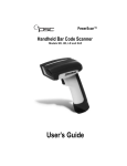
1
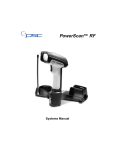
PowerScan™ RF
Handheld Bar Code Scanner
User’s Guide
PSC Scanning, Inc.
959 Terry Street
Eugene, Oregon 97402
Telephone: (541) 683-5700
Telefax: (541) 345-7140
PSC, the PSC logo, Quadralogic II and PowerScan are registered
trademarks of PSC Inc. All other trademarks and trade names
referred to herein are property of their respective owners.
All rights reserved. No part of the contents of this documentation or
the procedures described therein may be reproduced or transmitted
in any form or by any means without prior written permission of PSC
Inc. Owners of PSC Inc.'s products are hereby granted non-exclusive,
revocable license to reproduce and transmit this documentation for
the purchaser's own internal business purposes. Purchaser shall not
remove or alter any proprietary notices, including copyright notices,
contained on this documentation and shall ensure that all notices
appear on any reproductions of the documentation.
Should future revisions of this manual be published, you can acquire
printed versions by contacting PSC Customer Administration. Electronic versions will either be downloadable from the PSC web site
(www.pscnet.com) or provided on appropriate media. If you visit our
web site and would like to make comments or suggestions about this
or other PSC publications, please let us know via the “Contact PSC”
page.
Disclaimer
Reasonable measures have been taken to ensure that the
information included in this manual is complete and accurate.
However, PSC reserves the right to change any specification
at any time without prior notice.
Table of Contents
Unpack and Inspect Your Scanner .............................................. 1
References................................................................................... 1
Quick Start Instructions ................................................................ 1
Installing the Battery .............................................................. 2
Verifying Scanner Operation ................................................. 3
Connecting the Base Station to the Host Terminal................ 3
Linking the Scanner to a Base Station .................................. 5
Verifying Scanner-to-Base Station Communications............. 6
Using the PowerScan RF System................................................ 7
Battery Charging and Maintenance ....................................... 7
Tips for Extending Battery Life .............................................. 8
Disposing of Batteries............................................................ 8
Four Station Charger ............................................................. 9
How to Scan............................................................................... 10
Depth of Field ...................................................................... 11
LED and Beeper Indications ...................................................... 15
Active Symbologies ............................................................. 19
Enhanced Scanning for Hard-to-Read Bar Codes .............. 19
Laser Cautions ........................................................................... 21
Radio Frequency Interference.................................................... 22
Maintenance............................................................................... 23
Troubleshooting ......................................................................... 24
Sample Bar Codes ..................................................................... 25
User’s Guide
i
Unpack and Inspect Your Scanner
After unpacking your new scanner, check the contents of the shipping carton to ensure all the items you ordered are included:
•
PowerScan™ RF handheld scanner
•
Battery Pack(s)
•
User’s Guide (this manual)
•
Optional Accessories that you ordered. (The scanner can be
purchased with or without accessory kits.)
If your package contains wrong or missing components, contact your
place of purchase. If there are damaged components, immediately file
a claim with the carrier. You may want to save your packing material
in case you need to ship the scanner at some later time.
References
For more information about this product, its associated publications,
software, and accessories, visit our website listed on the back cover of
this manual.
Quick Start Instructions
The basic steps below must be performed to set up the RF scanner.
Each of these steps is detailed in this manual.
•
Installing the Battery
•
Verifying Scanner Operation
•
Connecting the Base Station to the Host Terminal
•
Linking the Scanner to a Base Station
•
Verifying Scanner-to-Base Station Communications
User’s Guide
1
Installing the Battery
To assure maximum usage, batteries should always
be fully charged before their initial use. (See Battery
Charging and Maintenance on page 7.)
NOTE
Orient the battery as shown in Figure 1, then push it into the scanner
until it snaps in place. To remove the battery, push in on the release
tabs on both sides of the battery’s base and pull it straight out of the
scanner.
Figure 1. Installing the Battery
1
1.
2
1
Battery Release Tabs
PowerScan™ RF Scanner
Verifying Scanner Operation
Once a charged battery has been installed in the scanner, scan the
sample bar codes in the back of this manual that correspond to the
symbologies your scanner is programmed to read. If unsure how to
do this, see the section on How to Scan in this manual. The system
may signal with one or a combination of indicators depending upon
how the scanner and Base Station are programmed to respond (see
LED and Beeper Indications for details). If your scanner fails to read a
sample bar code of a symbology it’s programmed to read, turn to the
section titled, Troubleshooting.
Connecting the Base Station to the Host Terminal
NOTE
1.
It is important that the interface (I/F) cable be connected to the Base Station prior to applying power
to the system. This is because the interface type
(RS-232, IBM, Keyboard Wedge, etc.) is selected by
the Base Station subject to the I/F cable it is connected to at the time of power-up.
Connect the I/F cable to the Base Station (see Figure 2A). The
I/F cable is inserted into the connector and the cable retainer
clip is rotated over the cable overmold until the retainer
snaps in place (see Figure 2B). To disconnect the cable, push
in on the retainer (away from the catch on the plastic wall) to
release it and enable it to swing upward, allowing the cable
to be pulled free (see Figure 2C).
Figure 2. Connecting/Disconnecting the Interface (I/F) Cable
a
b
c
User’s Guide
3
2.
Consult your Host Terminal manual to determine the
required communication parameters for the Host Terminal
(e.g., baud rate, parity, etc.) and, if necessary, modify the programmed parameters to be compatible with those requirements. Scanner and Base Station programming is performed
using one of the following:
- Configurator Express™ Programming Software
- PowerScan™ Bar Code Scanner Programming Guide
See References for more information about how to
obtain software and manuals for this product.
NOTE
CAUTION
The Host Terminal manual should also be consulted
as to whether power must be turned off before connecting peripheral devices. Ensure that the correct
procedure is followed to avoid damage to equipment or interruption of system functions.
3.
Connect the I/F cable to the proper port on the Host Terminal
(check your Host Terminal manual to determine hardware
requirements).
4.
Connect the AC Adapter's power cord at the Base Station and
plug the AC/DC adapter in at the wall outlet (see Figure 3).
The Base Station’s POWER LED should be illuminated when
the unit is properly connected to power.
Figure 3. Connecting Power to the Base Station
4
PowerScan™ RF Scanner
5.
Apply power to the Host Terminal.
6.
Verify communication with the Host Terminal by aiming the
linked scanner at a sample bar code from the back pages of
this manual, and pulling the trigger (see How to Scan for tips
about scanning bar codes). Confirm that the scanner/Base
Station sent the data to the host terminal. If not, see the section, Troubleshooting. Once all communications are verified,
the system is ready for use.
Linking the Scanner to a Base Station
To link a scanner to a Base Station, simply scan the Base Station ID
bar code located on the top of the desired Base Station. As the scanner
searches for the Base Station, a short beep is heard as it seeks for the
correct channel. When the Base Station responds to the request, the
scanner’s beeper will either sound a "Link Granted," or "Link Denied"
signal (see the section, LED and Beeper Indications for more information).
The existing Base Station system configuration can be automatically
downloaded to the scanner. This automatic download feature is configurable and can be disabled. See the Systems Manual for more
information about this feature. If downloading occurs, a slight delay
with link verification announcement will occur.
CAUTION
User’s Guide
Since a new/replacement scanner may have been
shipped with a custom configuration or may have
been modified with other special programming, it
may not be desirable to download a potentially
older configuration from an existing Base Station.
In this case, reference the Systems Manual, or the
Configurator Express™ On-Screen Programming
Software and consider uploading the scanner’s
newer configuration to the Base Station prior to
linking.
5
Verifying Scanner-to-Base Station Communications
Point the linked scanner at a sample bar code from the back pages of
this manual, and pull the trigger (see How to Scan for tips on scanning
bar codes). Watch the TX/RX (transmit/receive) indicator LED on the
Base Station and/or scanner green LED while scanning the bar code.
The LEDs should flash momentarily as the two devices communicate.
If no communication is indicated, refer to the troubleshooting section
of the Systems Manual.
When the scanner is programmed to do so, communication can also
be indicated by a second "acknowledgement" tone 1 that is sounded
after a "good read" tone. If a transmission error beep (warble) is heard
following a "good read" tone instead of the single acknowledgement
tone, communication between the devices may have failed2. Refer to
the sections Using the PowerScan RF System, and Troubleshooting for
possible remedies, should this occur.
1. See LED and Beeper Indications for more details about beeper signals.
2. Other reasons for a "warble" are that the Base Station may be configured differently than
the scanner, or that the system’s interface doesn’t support the symbology (bar code type)
you’re trying to scan.
6
PowerScan™ RF Scanner
Using the PowerScan RF System
This section covers the following topics:
•
Battery Charging and Maintenance
•
How to Scan
•
LED and Beeper Indications
Battery Charging and Maintenance
NOTE
When the scanner is in use, a low battery condition
is indicated by a repeated two-flash signal from the
scanner’s green LED every time the trigger is pulled
before the laser is enabled. This indicator may have
been disabled via custom programming. See LED
and Beeper Indications for more information.
Seat the scanner in the Base Station as shown in Figure 4, ensuring
that the battery fully engages the station’s metal contacts. The
CHARGE LED on the Base Station should flash, indicating the battery is charging.
Figure 4. Charging the Battery
User’s Guide
7
Rapid flashing indicates that charging is taking place. Rapid charging
occurs when the battery temperature is between 10°C (50°F) and 46°C
(115°F), and/or voltage of the battery is between 2.0 and 3.2V. Charge
time is less than 4.2 hours. Rapid charge ends with the battery at
approximately 90 to 95% capacity. The CHARGE LED remains on
steady when trickle charging or after the charge cycle is complete.
A scanner may be charged simultaneously while
other scanners are in use with the Base Station.
NOTE
NOTE
Batteries will not charge if their temperature is
below 0°C (30°F). If a battery that is too cold is
inserted into the Base Station, the Charge LED will
not illuminate.
Tips for Extending Battery Life
Nickel Metal Hydride (NiMH) batteries will better hold a charge if
allowed to discharge at least once a week. The chemical reactions that
correspond to charge and discharge in a rechargeable battery should
occur to obtain the maximum number of charge/discharge cycles in
the battery. If a battery is removed from the scanner and stored, it
should be fully charged when stored. Batteries will lose the ability to
hold a charge when stored for long periods of time (weeks, months,
or longer).
Batteries will typically have about 30% charge capacity when
shipped. To assure maximum usage, the battery should be fully
charged before use.
Store your battery in a cool dry place. Do not leave your battery
exposed to direct sunlight or temperatures below 0°C (30°F) and
above 38°C (100°F).
Disposing of Batteries
There presently are no US, North America or World disposal requirements for NiMH batteries, so when they won't hold a charge anymore, the batteries can be disposed of, preferably through a recycling
center.
8
PowerScan™ RF Scanner
Four Station Charger
If you have a Four Station Charger, batteries are inserted for charging
as shown in Figure 5. A 90% rapid charge can be achieved in only two
hours when using this optional accessory, half the time than when a
Base Station is used for charging. The LEDs at each battery station
operate the same as the CHARGE LED on the Base Station, with
rapid flashing indicating that rapid charging is taking place and on
steady during trickle charging or when the rapid charge cycle is finished.
NOTE
If you insert a battery into the Four Station Charger
and no LEDs illuminate, the battery may be too
cold. Batteries must be at 0°C or higher to charge.
Do not attempt to charge cold batteries, since placing them in the charger will curtail the charging of
other batteries already present in the unit.
Figure 5. Using the Four Station Charger Accessory
1
2
1.
Device Power LED
User’s Guide
2.
Station Charge LEDs
9
How to Scan
Figure 6 illustrates some tips to help get the best scanning results:
1.
The scanner must be pointed at a slight angle to the bar code.
Do not hold the scanner perpendicular to the bar code.
2.
The laser beam must cross the entire bar code. The scanner
cannot correctly read if the entire bar code is not scanned.
Figure 6. Scanning Tips
1
1
2
2
10
PowerScan™ RF Scanner
Depth of Field
There are currently four different range models for the scanner.
Depending upon the model type of your scanner, you’ll need to hold
the unit at a given distance from the bar code to achieve optimum
scanning results. The following diagrams provide depth of field
information for each of the models when scanning grade A, Code 39
bar codes: Standard Range (SR), High Density (HD), Long Range
(LR) and Extra Long Range (XLR).
Definition of a "mil"
A "mil" is equal to 0.001 inches. In the context of the illustrations in
this section, a mil represents the minimum bar code element width.
Thus a 5 mil bar code would have a minimum element width of 5
mils (or 0.005 inches).
Measurements are based on SR models set with the
standard 28° scan width (as opposed to the Half
Angle setting of 14°). Reference the Programming
Manual for more information about the Half Angle
feature.
NOTE
Specifications are subject to change without notice.
Figure 7. Depth of Field (SR)
Depth of Field
Paper Labels (SR decoded model, Code 39)
FRONT OF SCANNER
5 mil
7.5 mil
10 mil
15 mil
20 mil
40 mil
55 mil
1
0
10
User’s Guide
20
30
2
40
50
60
3
FEET
70
80
90 100
CENTIMETERS
4
110
120
5
130
140
150
160
170
11
See the section titled, Definition of a "mil" for more
information about reading this chart. Measurements
are based on HD models set with the standard 28°
scan width (as opposed to the Half Angle setting of
14°). Reference the Programming Manual for more
information about the Half Angle feature.
NOTE
Specifications are subject to change without notice.
Figure 8. Depth of Field (HD)
Depth of Field
FRONT OF SCANNER
Paper Labels (HD decoded model, Code 39)
3 mil
4 mil
5 mil
7.5 mil
10 mil
20 mil
1
0
12
2
5
3
INCHES
4
10
CENTIMETERS
5
6
15
7
8
20
PowerScan™ RF Scanner
See the section titled, Definition of a "mil" for more
information about reading this chart. Measurements
are based on LR models set with the a 14° scan
width (as opposed to the alternate Full Angle setting of 28°). Reference the Programming Manual for
more information about the Half Angle feature.
NOTE
Specifications are subject to change without notice.
Figure 9. Depth of Field (LR)
Depth of Field
FRONT OF SCANNER
Paper Labels (LR decoded model, Code 39)
7.5 mil
10 mil
15 mil
20 mil
40 mil
55 mil
1
0
10
20
30
2
40 50
3
60 70
4
5
FEET
6
7
8
9
80 90 100 110 120 130 140 150 160 170 180 190 200 210 220 230 240 250 260 270 280
CENTIMETERS
FRONT OF SCANNER
Reflective Labels (LR decoded model, Code 39)
40 mil
55 mil
70 mil
100 mil
1
2
3
4
5
6
7
8
9
10
11
12 13
FEET
14
15
16
17
18
19
20
21
22
0 10 30 50 70 90 110 130 150 170 190 210 230 250 270 290 310 330 350 370 390 410 430 450 470 490 510 530 550 570 590 610 630 650 670
CENTIMETERS
User’s Guide
13
See the section titled, Definition of a "mil" for more
information about reading this chart. Measurements
are based on XLR models set with a 10° scan angle
width.
NOTE
Specifications are subject to change without notice.
Figure 10. Depth of Field (XLR)
Depth of Field
FRONT OF SCANNER
Paper Labels (XLR decoded model, Code 39)
15 mil
20 mil
40 mil
55 mil
1
0
2
3
50
4
100
5
6
150
7
200
8
FEET
9
250
CENTIMETERS
10
11
300
12
13
350
400
14
15
450
FRONT OF SCANNER
Reflective Labels (XLR decoded model, Code 39)
40 mil
70 mil
100 mil
1 2 3 4 5 6 7 8 9 10 11 12 13 14 15 16 17 18 19 20 21 22 23 24 25 26 27 28 29 30 31 32 33 34 35 36
FEET
0
14
50
100
150
200
250
300
350
400
450
500 550 600 650 700
CENTIMETERS
750
800
850
900
950 1000 1050 1100
PowerScan™ RF Scanner
LED and Beeper Indications
The Base Station LED indicators and the scanner’s LEDs and beeper
are used to announce system status and perform other useful signals.
The tables below list the default function of each of the various indicators.
NOTE
Some LED and beeper indications can be disabled
or modified via scanner programming. The tables
indicate the default behavior of the indicators, with
shaded rows representing features that are programmable.
Table 1. Scanner GREEN LED Functions
LED
INDICATION
DURATION
COMMENT
Disable
Indication
100ms on, 900 ms off
Good Read
Indication
500 ms on
Program
Mode
Indication
500 ms on, 500 ms off
Continuous flashing
Indicates the scanner
is in Programming
Mode.
Field
Replaceable
Unit (FRU)
Indications
Varies. Consists of a
long flash followed by
multiple short flashes.
Enables service technicians to identify
Field Replaceable Unit
(FRU) errors.
Low Battery
Indication
User’s Guide
Two flashes at 100 ms
on, 350 ms off.
Indicates the scanner
has been disabled.
Indicates a bar code
has been read and
decoded.
Occurs at trigger pull
before the laser is
enabled. Indicates the
battery is in need of
recharging.
15
Table 2. Scanner YELLOW LED Functions
LED
INDICATION
Laser on
indication
DURATION
On Steady
COMMENT
The yellow LED illuminates whenever the
laser is on.
Table 3. Scanner BEEPER Functions
SPEAKER
INDICATION
Scanner Not
Currently
Linked
DURATION
Six beeps consisting of
20 ms on, 20 ms off
COMMENT
Indicates a bar code
was read before the
scanner was linked to
a Base Station.
100 ms on (short)
Good Read
Beep
250 ms on (medium)
500 ms on (long)
Partial Read
Bip
20 ms on
100 ms on (short)
Base Station
Acknowledgement
Beep
16
250 ms on (medium)
500 ms on (long)
Three programmable
functions are available. This indicates a
bar code has been
read and decoded.
A very short beep
("bip") is sounded
when one bar code of
a two-bar code pair
has been successfully
decoded.
Indicates a successful
bar code transmission
to the host (configurable), a successful
change of channel, or
a successful transmission of a new configuration to the host.
PowerScan™ RF Scanner
SPEAKER
INDICATION
Transmission Error
Beep
Link Beep
Unlink Beep
Field
Replaceable
Unit (FRU)
Indications
DURATION
High, then low, then high,
then low.
COMMENT
Indicates unsuccessful transmission to the
host.
Low, then medium, then
high.
Indicates a scanner
has been successfully
linked to a base station.
High, then medium, then
low.
Indicates a scanner
has been successfully
unlinked from a base
station.
Varies. Consists of a
long tone followed by
multiple short tones.
Enables service technicians to identify
Field Replaceable Unit
(FRU) errors.
Table 4. Base Station LED Functions
LED
INDICATION
DURATION
Lit for variable timea
TX/RX
(Transmit/
Receive)
Continuous rapid
flashing at power-up
Varies. Consists of a
long flash followed by
multiple short flashes.
User’s Guide
COMMENT
Indicates communications activity to or from
the Base Station.
Indicates a broken
radio.
Enables service technicians to identify
Field Replaceable Unit
(FRU) errors.
17
LED
INDICATION
DURATION
Continuous flashing
When a scanner is
nested in the station,
this indicates its battery is being quick
charged.
Lit Constantly
When a scanner is
nested in the station,
this indicates its battery is at or near full
charge.
Not Lit
A scanner is not
present or incorrectly
inserted into the station. It can also mean
the battery is below
0°C (too cold for
charge)
Lit Constantly
Indicates that power is
on.
Charge
(Battery)
Power
COMMENT
a. The LED remains on while the unit is actively processing code which
requires a TX/RX to occur. The duration of the LED is dependent upon
the length of the message.
18
PowerScan™ RF Scanner
Active Symbologies
The active (enabled) bar code symbologies in the standard factory
defaults are:
•
Code 39 (C39)
•
Code 128 (C128)
•
Interleaved 2 of 5 (I 2 of 5)
Your scanner should be pre-programmed with these standard factory
default settings, unless...
...it was shipped to you programmed with unique, customer configuration settings.
...you or another user have made changes to scanner programming.
Enhanced Scanning for Hard-to-Read Bar Codes
Decoded scanners can be programmed to decode extremely poor
quality bar codes by activating advanced Quadralogic II™ Decoding.
To select this feature, see the Programming Guide.
Scanner programming can also be performed using your PC and the
Configurator Express™ On-Screen Programming Kit.
Information about manuals, kits and programming
software for this product are available at our website. See the back cover for our web address.
NOTE
User’s Guide
19
Figure 11. Scanner Labeling and Nomenclature
2
RF
1
COVERED
BY ONE OR MORE OF THE
FOLLOWING PATENTS:
4,387,297 • 4,409,470 • 4,460,120
4,593,186 • 4,652,750 • 4,673,805
4,736,095 • 4,816,660 • 4,845,350
4,861,972 • 4,866,257 • 4,879,456
5,179,270 • 5,180,904 • 5,237,161
5,247,161 • 5,247,162 • 5,258,604
5,260,554 • 5,298,728 • 5,311,000
5,330,370 • 5,468,949 • 5,475,206
5,481,098
Other patents pending
4
3
5
CAUTION—LASER RADIATION WHEN OPEN. AVOID EXPOSURE TO BEAM.
6
1.
Trigger
4.
Tether Hook
2.
Scan Window
5.
Yellow LED
3.
Green LED
6.
Battery
NOTE
20
Figure 11 above shows label placement ONLY. For
actual regulatory, patent and other applicable information, view the labels on the product itself, or call
your nearest sales or service representative.
PowerScan™ RF Scanner
Laser Cautions
The PowerScan RF bar code scanner is certified in the U.S. to conform
to the requirements of DHHS/CDRH 21CFR Subchapter J for Class II
laser products (SR and LR) and Class IIIa (XLR). Class II and IIIa products are not considered to be hazardous. The scanner contains a Visible Laser Diode (VLD) at a wavelength of 650-670 nanometers and is
designed so that there can be no human access to harmful levels of
laser light during normal operation, user maintenance, or during prescribed service operations.
CAUTION
CAUTION
In the unlikely event that a bright laser spot is experienced rather than a scan line, do not stare into the
beam or attempt to repair the unit. Discontinue
operation and return the unit to your dealer. Note
that when using Marker Beam Mode, a single aiming dot is projected momentarily preceding a scan
line and is not considered a malfunction.
Do not open or otherwise service any components
in the optics cavity. Opening or servicing any part
of the optics cavity by unauthorized personnel may
violate laser safety regulations. The optics system
is a factory only repair item.
The PowerScan™ RF scanner is required to be used
in conjunction with the PSC Base Station, Model:
PowerScan RF Base Station.
NOTE
User’s Guide
21
Radio Frequency Interference
This device complies with Part 15 of the FCC Rules. Operation is subject to the following two conditions:
1.
This device may not cause harmful interference, and
2.
This device must accept any interference received, including
interference that may cause undesired operation.
This Class A digital apparatus complies with Canadian ICES-003.
Cet appareil numérique de la classe A est conforme à la norme NMB003 du Canada.
This equipment has been tested and found to comply with the limits
for a Class B digital device, pursuant to Part 15 of the FCC Rules.
These limits are designed to provide reasonable protection against
harmful interference in a residential installation. This equipment generates, uses and can radiate radio frequency energy and, if not
installed and used in accordance with these instructions, may cause
harmful interference to radio communications. However, there is no
guarantee that interference will not occur in a particular installation.
If this equipment does cause harmful interference to radio or television reception, which can be dertermined by turning the equipment
off and on, the user is encouraged to try to correct the interference by
one or more of the following measures:
22
•
Reorient or relocate the receiving antenna.
•
Increase the separation between the equipment and receiver.
•
Connect the equipment into an outlet on a circuit different
from that to which the receiver is connected.
•
Consult the dealer or an experienced radio/TV technician for
help.
PowerScan™ RF Scanner
Maintenance
The scan window will require occasional cleaning to remove
smudges, dust and other debris. To ensure optimal performance,
clean the Scan Window using a soft cloth or lens tissue dampened
with isopropyl alcohol (or equivalent). See Figure 12. The scanner
body can also be cleaned using this method.
Figure 12. Cleaning the Scan Window
User’s Guide
23
Troubleshooting
Troubleshoot your RF scanning system by performing the following
checks:
For the RF system, ensure that...
•
the battery is charged. See Battery Charging and Maintenance
on page 7.
•
the battery is properly installed. See Installing the Battery on
page 2.
•
the scanner is linked to the desired Base Station. See Linking
the Scanner to a Base Station on page 5.
•
the scanner is within reasonable operating range of the Base
Station, with no major obstructions between the radio units
such as thick walls or heavy machinery. (At the time of this
writing, maximum line-of-sight range is specified at 150 feet.)
•
there is no local signal interference with other radio-operated
equipment. Consult the Systems Manual concerning selection of alternate channels.
•
the Base Station is powered-on. You can verify the Base Station’s AC Adapter by using a known-good AC Adapter.
•
the Base Station interface cable is securely attached to the
host. Consult your technical support manager or refer to
your host system manual to identify the proper cable connection for the scanner. If necessary, verify interface cable function by using a known-good interface cable.
If the problem is specific to scanning, verify that...
24
•
the bar codes you are trying to scan are of satisfactory quality.
Bar code label verifiers are available from your dealer if you
need precise reporting of label details. Bar codes that are
damaged (wrinkled, smudged, or torn) may cause the scanner to read poorly or not at all. If bar code quality seems to be
the problem, check to see if the scanner will read a sample
bar code from the following pages.
•
the programmable setting for advanced Quadralogic II™
decoding is set optimally for your system. (See Enhanced
Scanning for Hard-to-Read Bar Codes on page 19.)
PowerScan™ RF Scanner
Sample Bar Codes
Use these test bar codes to check the scanner’s ability to read the various symbologies represented.
Code 128
C o d e
1 2 8
. T e s
t
Code 39
C
O
D
E
3
9
.
T
E
S
T
Interleaved 2 of 5
0 1 2 3 4 5 6 7 8 9
Standard 2 of 5
1 2 3 4 5 6 7 8 9 0
Codabar
A $ 9 9 . 9 5 A
Code 93
C
o d e
9 3
. T e s
t
MSI/Plessey
14476925
User’s Guide
4
25
UPC-A
00112 23344
0
0
4 9
UPC-A with 2 digit Add-on
60992
0
01118
7
6 9 0 0 0
UPC-A with 5 digit Add-on
0
08029
51041
8
UPC-E
0
998875
0
EAN-8
0021 0126
EAN-13
1
26
101234 567891
PowerScan™ RF Scanner
User’s Guide
27
DECLARATION OF CONFORMITY
PSC hereby declares that the Equipment specified below has
been tested and found compliant to the following Directives
and Standards:
Directives:
EMC 89/336/EEC
Low Voltage 73/23/EEC
R & TTE 1999/5/EC
Standards:
ETS 300 683:1997 ETS 300 220-3:2000
EN60825-1:1996
EN60950:1997
Equipment
Type:
Product:
Bar Code Scanning Equipment
PowerScan™ RF Bar Code Scanner
Charles W. Vanlue
Director, Corporate Quality
PSC, Inc.
959 Terry Street
Eugene, OR 97402
U.S.A.
Nigel Davis
Vice President
Europe, Middle East & Africa
PSC Bar Code Ltd.
Axis 3, Rhodes Way
Watford, England
WD24YW
UK
Asia Pacific
Italy
PSC Hong Kong
Hong Kong
Telephone: [852]-2-584-6210
Fax: [852]-2-521-0291
PSC S.p.A.
Vimercate (MI), Italy
Telephone: [39] (0) 39/62903.1
Fax: [39] (0) 39/685496
Australia
Japan
PSC Asia Pacific Pty Ltd.
North Ryde, Australia
Telephone: [61] 0 (2) 9878 8999
Fax: [61] 0 (2) 9878 8688
PSC Japan K.K.
Shinagawa-ku, Tokyo, Japan
Telephone: 81 (0)3 3491 6761
Fax: 81 (0)3 3491 6656
France
Latin America
PSC S.A.R.L.
LES ULIS Cedex, France
Telephone: [33].01.64.86.71.00
Fax: [33].01.64 46.72.44
PSC S.A., INC.
Miami, Florida, USA
Telephone: (305) 539-0111
Fax: (305) 539-0206
Germany
United Kingdom
PSC GmbH
Darmstadt, Germany
Telephone: 49 (0) 61 51/93 58-0
Fax: 49 (0) 61 51/93 58 58
PSC Bar Code Ltd.
Watford, England
Telephone: 44 (0) 1923 809500
Fax: 44 (0) 1923 809 505
Corporate
Headquarters
PSC Inc.
Portland, OR
Telephone: (503) 534-3553
Fax: (503) 534-3555
PSC Inc.
959 Terry Street
Eugene, OR
Telephone: (541) 683-5700
Fax: (541) 686-1702
www.pscnet.com
Printed on recycled paper
© 2001 PSC INC.
R44-2100 (Rev. A)
Printed in USA (8/01)