1
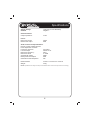
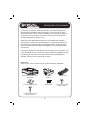
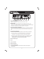
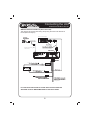
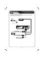
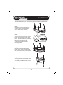
ASS1008
8” SLIMLINE ACTIVE SUBWOOFER
WITH BUILT IN AMPLIFIER
Instruction Manual
ACTIVE
E
SUBWO
OOFER
R
MAX
www.dnaaudio.com.au
Index
Specifications………...................…………………………..…………...…4
Introduction & Inclusions……….………...................…..…………...……5
Safety……….………...................…..…………................................……6
Unit Features…………………...…………………......………....…….....…7
Connecting The Unit: RCA Sub Outputs......………..........…...........……8
Connecting The Unit: Speaker Outputs..…………...……................……9
Installation……………......................................……...……….....……...10
Trouble Shooting……......................................……...……….....….…...11
Thank you for purchasing this DNA Designer Audio product. It is
designed to give you many years of enjoyment. DNA Designer Audio
recommends installation by a professional installer.
Read all instructions fully before installation.
RCA leads and power cable are recommended for the installation of
this product. Sold separately.
See www.dnaaudio.com.au for our complete product range.
3
Specifications
Supply Voltage:
Ground:
13.8V DC (10-16V allowable)
Negative
General features:
Output impedance:
4 ohm
Power:
Max Power output
RMS Power output
320W
80W
Audio controls and specifications:
Remote control supplied for bass
boost adjustment in vehicle
Frequency response:
30~120Hz
Low level input:
200mV~2.0V
Bass boost frequency:
50Hz
Bass boost level:
0~12dB
S/N Ratio @ 100Hz:
98dB
RMS power consumption
80W
Quiescent Power Dissipation:
5W
Measurements:
Weight:
319mm L x 215mm W x 70mm H
4.3kg
NOTE: Specifications and design are subject to modification without notice due to improvement in technology.
4
Introduction & Inclusions
An extremely compact, slimline subwoofer. The ASS1008 has been
developed with flexibility and functionality in mind. The 70mm high
active subwoofer can be mounted vertically or horizontally. It takes up
a minimum amount of space in the boot, under the parcel shelf and
virtually disappears under the seat.
Inside the ASS1008 sealed enclosure is a 320 Watt Max amplifier
that supports a powerful sound experience. The subwoofer delivers a
clear and strong sounding bass. Equipped with RCA & speaker level
inputs this subwoofer can easily be integrated using existing speaker
connections.
If your goal is quality sound without compromising your boot space, this
is the subwoofer for you. Small and compact allowing installation under
the passenger seat. Don’t be fooled by the size the 320 Watt Max
amplifier ensures you are not short on power.
Inclusions
Here is a list of the contents in your 8” Slimline Active subwoofer.
MAX
MIN
Slimline Active subwoofer
(ASS1008)
Bass Boost
Control
4 x Mounting Brackets
15Amp Fuse
10 x Mounting Screws
(4mm x 15mm)
5
Wiring Loom
8 x Mounting Screws
(4mm x 8mm)
Safety
Alteration or modifications carried out without appropriate authorisation may
invalidate the users right to operate the equipment and void warranty.
CAUTION
•
Never replace the fuse with one of greater value. Use of improper fuse
could result in overheating, smoke and could cause injury including burns.
WARNING
•
Do not touch amplifier with wet hands. Risk of shock.
•
For traffic safety and to maintain safe driving conditions, keep the volume
low enough so that you can hear normal traffic sounds.
•
Check the connections of the power supply and speakers regularly. If a
fuse blows solve the problem before replacing with a new fuse of the same
rating.
•
To prevent malfunction of the amplifier and speakers, the protective
circuit will cut the power supply to the amplifier. In such case, switch off
the system and check all connections. Detect the cause and solve the
problem.
•
Contact your installer or dealer if you can not solve the problem.
•
To prevent an electric shock or short circuit during installation be sure to
disconnect the negative battery terminal beforehand.
•
Confirm that no parts are behind the panel when drilling holes for
installation of the amplifier. Be sure to protect cables and important
equipment such as fuel lines, brake lines and electrical wiring from
damage.
•
DO NOT allow amplifier to come into contact with liquids. Electrical shock,
amplifier damage and speaker damage could result. In addition, the
amplifier surface and of any attached speakers could become hot to touch
and minor burns could result.
•
If there is smoke or any peculiar odor present during use unplug the
power cord.
6
Unit Functions
1. Remote Control Input
Plug in to operate the remote subwoofer volume control.
2. Phase Switch
Use this switch to help compensate for time alignment issues in your
system. Such problems usually occur when the subwoofer is further away to
the listener compared to the vehicle speakers in the system.
3. Crossover Frequency Adjustment
This control permits you to define the frequency you want the subwoofer to
receive. The subwoofer will reproduce all sound below the frequency you
set.
4. Gain (Volume) Adjustment
a.) After you have installed your system, turn this control to a minimum.
b.) Turn the head unit on; the subwoofer will turn on via the remote
connection. Turn the head unit volume to about 66% full level.
c.) Slowly turn up the subwoofer gain control unit, you will hear a small
amount of distortion. Then reduce the level until the distortion is
completely gone. Leave the control at this setting.
5. Power indicator light
6. Fuse
7. Power Terminals
8. High Level Inputs
9. Low Level RCA Inputs
Low level RCA inputs are recommended to deliver audio signal to
the subwoofer.
7
Connecting the Unit
USING RCA SUB OUTPUTS
WIRING USING RCA SUB OUT (Recommended)
This diagram shows the ideal wiring setup using the head units SUB OUT
RCA’s (External Output)
Head Unit Audio Outputs
Connect to run the bass
volume control
2x
negative
2x
2x
Dont need to be connected for this
wiring method
IF YOUR HEAD UNIT DOES NOT HAVE RCA OUTPUTS SEE THE
SPEAKER OUTPUT WIRING METHOD ON THE NEXT PAGE.
8
Connecting the Unit
USING SPEAKER OUTPUTS
WIRING USING SPEAKER OUTPUTS
If your head unit does not have RCA outputs use the wiring diagram below.
This method wires into speaker outputs.
Head Unit Audio Outputs
Connect to run the bass
volume control
2x
(Yellow) + & - speaker
wires to head unit
(Grey) + & - speaker
wires to head unit
negative
2x
2x
9
Installation
Before you drill or cut any holes, investigate your car’s layout very carefully.
Take special care when you work near the gas tank, fuel lines, hydraulic lines
and electric wiring.
Step 1:
Place the mounting brackets on the
aluminum base and fix them tightly
with the 4mm x 8mm screws.
Step 2.
Find a suitable location in the vehicle in
which to mount the subwoofer. A typical
location is shown (right). Other areas
include: boot and under the parcel shelf.
Make sure there sufficient air
circulation around the intended
mounting location.
Step 3.
Place the subwoofer in the desired
location. Mark screw mounting points
and drill out with 2.5mm (1/8 inch) drill.
Mount using the 4 x 15mm screws.
MIN
10
MAX
Step 4
Attaching the bass boost remote control,
mount with mounting screws (4mm x 15mm)
at an easily accessible location such as
under the dashboard.
Trouble Shooting
For advice on simple problems during the course of installation, debugging and
general use of the active subwoofer please check the table below:
ISSUE
OPTIONS
Ensure ground wired is earthed correctly.
Power Indicator
Light Off
Check the bass boost and wiring loom is fully plugged in,
please check the connection.
Fuse has blown, please change the fuse.
Check +12V wiring connection.
Sound Distortion Adjust the GAIN control. See page 7 for details.
Ensure the bass boost control is plugged in properly.
Speakers are
out of sound
Adjust the PHASE control. See page 7 for details.
Head unit audio output wires.
Sound noise
(only when
starting the
engine)
The signal input line is placed too close to the power
cables. Keep them as far away as possible.
11
www.dnaaudio.com.au