1
Operating Instructions
InRoom Controller
for DX 21-86
and CW 40-150
Contents
1. Presentation of the system ........................................................................................5
2. Hardware components ...............................................................................................6
2.1 I/O controller ......................................................................................................................................6
2.1.1 Board design .............................................................................................................................6
2.1.2 Assignment - I/O controller ........................................................................................................7
2.2 EDIO - Extension board for digital in- and outputs ............................................................................9
2.2.1 Board design .............................................................................................................................9
2.2.2 Assignment - EDIO1................................................................................................................10
2.2.3 Assignment - EDIO2................................................................................................................11
2.3 EAIO - Extension board for analogous in- and outputs ...................................................................12
2.3.1 Board design ...........................................................................................................................12
2.3.2 Assignment - EAIO ..................................................................................................................13
2.4 EBUS - Extension board for 2x RS485 bus .....................................................................................14
2.4.1 Board design ...........................................................................................................................14
2.4.2 Assignment - EBUS.................................................................................................................14
2.5 InRoom Controller Board .................................................................................................................15
2.5.1 Board design ...........................................................................................................................15
3. Operator interface ....................................................................................................16
3.1 I/O Controller ...................................................................................................................................16
3.2 Operational elements of the InRoom Controller ..............................................................................18
4. Bus communication .................................................................................................19
4.1 Bus with InRoom Controller + IOC ..................................................................................................20
4.2 Special cases ..................................................................................................................................20
5. Controller start ..........................................................................................................21
6. Operation ...................................................................................................................25
6.1 Info level ..........................................................................................................................................25
6.1.1 Info commands ........................................................................................................................25
6.1.2 Info overview ...........................................................................................................................26
6.2 Control level .....................................................................................................................................32
6.2.1 Overview structure ..................................................................................................................32
6.2.2 Control commands ..................................................................................................................33
6.2.3 Control overview ......................................................................................................................34
6.3 Service level ....................................................................................................................................54
6.3.1 Service overview .....................................................................................................................54
6.4 Default configurations ......................................................................................................................81
6.4.1 Preconfigurations ....................................................................................................................89
7. Alarm treatment ........................................................................................................90
7.1 Alarm display ...................................................................................................................................90
7.2 Alarm messages..............................................................................................................................91
7.3 Component-related alarms ..............................................................................................................92
7.4 Alarm Reset.....................................................................................................................................92
7.5 Alarm texts in case of hardware errors ............................................................................................93
8. Configuration notes .................................................................................................94
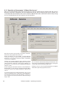
8.1 Loading a new Software ..................................................................................................................95
8.1.1 Operation of the program "C7000-Service.exe" ......................................................................96
9. Network Management Card .....................................................................................97
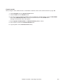
9.1 Quick Configuration .........................................................................................................................97
9.2 Access a Configured Unit ..............................................................................................................102
9.3 Recover From a Lost Password .....................................................................................................105
InRoom Controller - Operating Instructions
3
This manual is based on the software versions IOC-V2.23 and AT-V0.90.
4
InRoom Controller - Operating Instructions
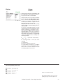
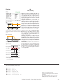
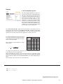
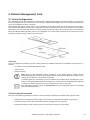
1. Presentation of the system
The InRoom Controller offers maximum possible operating safety for industrial applications and a versatile
operator interface. There are two interfaces with one
controller.
The InRoom Controller works by having each cooling
unit possess its own controller while all controllers can
be linked together in a bus system.
This way a natural redundancy is obtained that causes
the system to function with the least expense.
The second interface can be accessed using a computer. Using the screen of a Laptop or PC provides the
best way of visualizing parameter settings. This is the
most comfortable way of doing a component-related
configuration.
Beyond the basic air conditioning functions, the control
system provides some interesting features like an intelligent management of high/low pressure-alarms, a proportional fan speed control which opens a wide spectrum
of applications and time-based functions like:
- week timer
- unit sequencing within definable unit groups
The heart of the control system is the I/O controller on
which up to 4 EAIO/EDIO boards for additional in- and
outputs can be installed. The exploitation of the third
dimension provides maximum accessibility and an easy
board exchange in case of modifications.
The control systems manages four busses:
1. IIC-bus for the communication between the I/O
controller and the EAIO/EDIO boards.
2. RS485 IO-bus for the communication among the
cooling units.
3. RS485 BMS-bus for the communication with a
building management system.
4. RS485 Aux-bus for the communication with optional components capable of bus connection.
For service purposes like software download and control
by a remote computer a RS232 interface is located on
the I/O controller in the same way as on the InRoom
Controller interface.
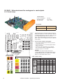
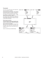
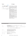
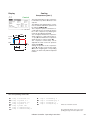
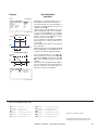
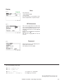
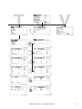
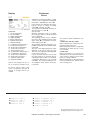
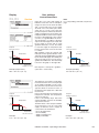
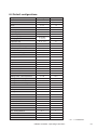
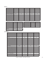
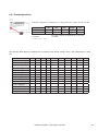
Analogous (A) and digital (D) in- and outputs
A-IN
A-OUT
D-IN
D-OUT
Interfaces
IOC-board
5
4
11
7
EAIO-board
4
4
/
/
EDIO-board
/
/
8
6
2 x RS485 IO-bus, terminals
4 x IIC-Bus, DB-15
EBUS conn. DB-15
RS232, DB-9
M a x i mu m e q u i p m e n t
IOC + 4 EAIO
21
20
11
7
IOC + 4 EDIO
5
4
43
31
IOC-board
EAIO-board
IIC-Bus, DB-15
EDIO-board
IIC-Bus, DB-15
EBUS-board
I/O board conn. DB-15
RS485 BMS-bus, terminals
RS485 Aux.-bus, terminals
Operator interface board
2 x RS485 IO-bus + BMS,
terminals
2 x RS232 BMS + service,
DB-9
InRoom Controller - Operating Instructions
5
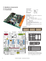
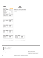
2. Hardware components
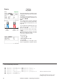
2.1 I/O controller
Technical Data:
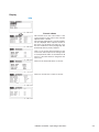
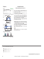
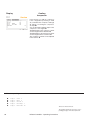
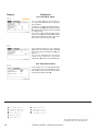
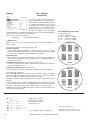
2.1.1 Board design
Voltage supply:
Power consumption:
Fuse:
Operating temp.:
Storage temp.:
24(+15%) VAC
9.6 VA
2 A time-lag
5°C...40°C
-30°C...60°C
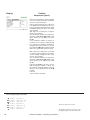
Onboard LEDs
The function of the digital inputs is displayed by
green LEDs:
ON:
Voltage present
OFF:
No voltage (alarm, failure)
The function of the digital outputs is displayed by
red LEDs:
ON:
Relay active
OFF:
Relay passive
The OK-LED displays the I²C-bus clock.
The TX1/RX1-LEDs indicate data traffic on the
I/O bus (port 1).
The Error-LED lights up at any time, when an alarm
has occurred.
Pin position
Service port
RS232
JP 7
DIP-switches
for bus ID
1
10 21
30 41
50
11
20 31
40 51
60
plug for EBUS JP 9 JP 8
ext. board
Jumper setting depending on sensor types
OK-LED
TX1-LED
RX1-LED
Error-LED
Bus driver
2
AIN 2
3
AIN 3
4
AIN 4
5
AIN 5
6
0-10V
4 sockets
for
EDIOs/
EAIOs
AIN 1
4-20mA
Analogous input
Jp n° Pos.1-2 Pos.2-3
PT1000 PT100
Jumper for software download
Jp n°
Pos. 1-2
Pos. 2-3
7
operation
download
Termination jumper
Jp n°
Function, when set
JP 6
1
I/O-bus Port 1 termin. (Pos.1-2)
JP 1
8
EBUS Port 2 termination
9
EBUS Port 3 termination
Jp 1 has to be set if the I/O controller represents
the first or last unit in the I/O bus.
green LEDs for
digital inputs 1-11
6
JP 2 3 4 5
red LEDs for
digital outputs 1-7
Jp8 and Jp9 have to be set if no EBUS extension
board is present. On the contrary, they have to
be removed to enable the two extension RS485
busses on a plugged EBUS extension board.
InRoom Controller - Operating Instructions
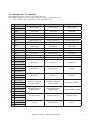
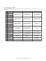
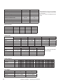
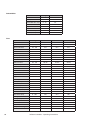
2.1.2 Assignment - I/O controller
The assignment depends on the unit version (DX1, DX2, CW).
DX1 - Single refrigerant circuit. DX2 - Dual refrigerant circuit. CW - Chilled water circuit.
E.g.: PA311D -> DX1, PGCW452U -> DX2, PCW900D -> CW
Pin Designation
DX1
DX2
CW
Power supply
Power supply
Power supply
1
24VAC
2
GND
3
GND
Reserved
Reserved
Reserved
4
Din 1
Fan failure
Fan failure
Fan failure
5
Din 2
Compressor failure
Compressor failure 1
Pump failure 1
6
Din 3
Low pressure
Low pressure 1
Chiller failure
7
Din 4
E-reheat failure 1-3
E-reheat failure 1-3
E-reheat failure 1-3
8
Din 5
Filter alarm
Filter alarm
Filter alarm
9
Din 6
Humidifier failure/
ENS 20µS
Humidifier failure/
ENS 20µS
Humidifier failure/
ENS 20µS
10
Din 7
Water detection
Water detection
Water detection
11
Din 8
Ext. alarm 1
Compressor failure 2
Ext. alarm 1
12
Din 9
Ext. alarm 2
Low pressure 2
Ext. alarm 2
13
Din 10
Remote on/off
Remote on/off
Remote on/off
14
Din 11
Fire stat
Fire stat
Fire stat
15
Dout 1 (NO)
16
Dout 1 (COM)
Enable fan
Enable fan
Enable fan
17
Dout 1 (NC)
18
Dout 2 (NO)
19
Dout 2 (COM)
Compressor
Compressor 1
Pump 2
20
Dout 2 (NC)
21
Dout 3 (NO)
22
Dout 3 (COM)
E-reheat 1
E-reheat 1
E-reheat 1
23
Dout 3 (NC)
24
Dout 4 (NO)
25
Dout 4 (COM)
Dout 4 (NC)
E-reheat 2 / Hot gas
reheat / HWR*
E-reheat 2 or HWR*
26
E-reheat 2 / Hot gas
reheat / HWR*
27
Dout 5 (NO)
28
Dout 5 (COM)
Dout 5 (NC)
Dehumidification or
Hotgas-bypass
On/off Humidifier or ENS
29
Dehumidification or
Hotgas-bypass
30
Dout 6 (NO)
31
Dout 6 (COM)
Common alarm 1
Common alarm 1
Common alarm 1
32
Dout 6 (NC)
33
Dout 7 (NO)
34
Dout 7 (COM)
Louver
Compressor 2
Louver
35 Dout 7 (NC)
*HWR - hot water reheat
InRoom Controller - Operating Instructions
7
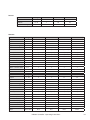
Assignment - I/O controller (continued)
Pin Designation
DX2
CW
Active sensor 1
Active sensor 1
Active sensor 1
36
+15V
37
GND
38
Ain 1
Room/return air temp.
Room/return air temp.
Room/return air temp.
39
Ain 2
Room/return air humidity
Room/return air humidity
Room/return air humidity
40
+15V
41
GND
Active sensor 2
Active sensor 2
Active sensor 2
42
Ain 3
Supply temperature
Supply temperature
Supply temperature
43
Ain 4
Supply humidity
Supply humidity
Supply humidity
44
+Ub
45
GND
46
Ain 5
47
GND
Passive sensor 3
Water temperature (CW)
Pt100 / 1000
3 or 4 conductors
Passive sensor 3
Water temperature (CW)
Pt100 / 1000
3 or 4 conductors
Passive sensor 3
Water temperature 1 (CW)
Pt100 / 1000
3 or 4 conductors
48
Aout 1
49
GND
Fan
Fan
Fan 1
50
Aout 2
51
GND
GE/CW valve/pump 1 or
actual temp.
GE/CW valve/pump 1 or
actual temp.
CW valve/pump 1
or actual temp.
52
Aout 3
53
GND
Humidifier/ENS or
actual humidity
Humidifier/ENS or
actual humidity
Humidifier/ENS or
actual humidity
54
Aout 4
55
GND
G-valve/pump 2
G-valve/pump 2
CW2-valve/pump 2
56
Port 1-H
57
Port 1-L
RS485-I/O-bus
RS485-I/O-bus
RS485-I/O-bus
58
Port 1-H
59
Port 1-L
RS485-I/O-bus
RS485-I/O-bus
RS485-I/O-bus
60
+15V
X10 SUB-D 15
X11 SUB-D 15
X12 SUB-D 15
Reserved
Bus 3
I2C
Bus 3
I2C
Bus 3
I2C
Reserved
EDIO1 (socket1) Bus 3
I2C
EDIO2 (socket2) Bus 3
I2C
EAIO1 (socket3)
I2C
Bus 3
Reserved
EDIO1 (socket1) Bus 3
I2C
EDIO1 (socket1)
EDIO2 (socket2) Bus 3
I2C
EDIO2 (socket2)
EAIO1 (socket3)
I2C
EAIO1 (socket3)
Bus 3
X13 SUB-D 15
Bus 3 I2C EDIO/EAIO
(socket 4)
Bus 3 I2C EDIO/EAIO
(socket 4)
Bus 3 I2C EDIO/EAIO
(socket 4)
X14 SUB-D 15
EBUS exp. (plug)
EBUS exp. (plug)
EBUS exp. (plug)
X15 SUB-D 9
8
DX1
RS232 service port (plug) RS232 service port (plug) RS232 service port (plug)
InRoom Controller - Operating Instructions
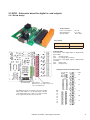
2.2 EDIO - Extension board for digital in- and outputs
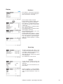
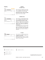
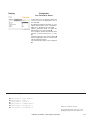
2.2.1 Board design
Technical Data:
Power consumption:
Operating temp.:
Storage temp.:
10.1 VA
5°C...40°C
-30°C...60°C
Pin position
1
10 21
30
11
20 31
40
Onboard LEDs
The function of the digital inputs is displayed by
green LEDs:
ON:
Voltage present
OFF:
No voltage (alarm, failure)
The function of the digital outputs is displayed by
red LEDs:
ON:
Relay active
OFF:
Relay passive
Enlarged section for onboard LEDs
LDO
13
12
green LEDs for
red LEDs for
digital inputs 12-19 digital outputs 8-13
of the first EDIO-board
The EDIO-board is an expansion board for digital
inputs and outputs. It can be attached to the I/O
controller board at any of the four sockets and will
be recognized by the IOC after a self test.
11
LDI
19
18
17
16
15
14
13
12
InRoom Controller - Operating Instructions
8
10
9
9
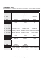
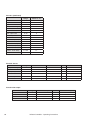
2.2.2 Assignment - EDIO1
The assignment depends on the unit version (DX1, DX2, CW). For more information, see „2.1.2 Assignment - I/O Controller“
on page 7.
Pin Designation
DX1
DX2
CW
1
Din 12
UPS
UPS
UPS
2
Din 13
Pump 1 failure
Pump 1 failure
Free
3
Din 14
Pump 2 failure
Pump 2 failure
Pump 2 failure
4
Din 15
Drycooler failure
Drycooler failure
Free
5
Din 16
CW disable/DX enable or
Ext. alarm 3
CW disable/DX enable or
Ext. alarm 1
Ext. alarm 3
6
Din 17
Ext. alarm 4
Ext. alarm 2
Ext. alarm 4
7
Din 18
ENS 5µS
Ext. alarm 3/ENS 5µS
ENS 5µS
8
Din 19
Phase control
Phase control
Phase control
9
Dout 8 (NO)
10
Dout 8 (COM)
Pump 1
Pump 1
Free
11
Dout 8 (NC)
12
Dout 9 (NO)
13
Dout 9 (COM)
Drycooler 1
Drycooler 1
Free
14
Dout 9 (NC)
15
Dout 10 (NO)
Drycooler 2 or winter
operation
Drycooler 2 or winter
operation
Winter operation
16
Dout 10 (COM)
17
Dout 10 (NC)
18
Dout 11 (NO)
19
Dout 11 (COM)
20
Dout 11 (NC)
21
Dout 12 (NO)
22
Dout 12 (COM)
23
Dout 12 (NC)
24
Dout 13 (NO)
25
Dout 13 (COM)
26
Dout 13 (NC)
27
PWM1
28
GND
29
PWM2
30
GND
X10 SUB-D 15
10
Drycooler 2 or winter/sum- Drycooler 2 or winter/sumWinter/summer operation
mer operation
mer operation
Drycooler 2 or summer
operation
Drycooler 2 or summer
operation
summer operation
Pump 2
Pump 2
Pump 2
E-reheat 3
E-reheat 3
E-reheat 3
Humidifier on/off /ENS
Louver
Free
Electrical
expansion valve
Electrical
expansion valve
Free
E-reheat 1 (proportional)
E-reheat 1 (proportional)
E-reheat 1 (proportional)
Bus 3 I2C (plug)
Bus 3 I2C (plug)
Bus 3 I2C (plug)
InRoom Controller - Operating Instructions
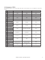
2.2.3 Assignment - EDIO2
The assignment depends on the unit version (DX1, DX2, CW). For more information, see „2.1.2 Assignment - I/O Controller“
on page 7.
Pin Designation
DX1
DX2
CW
1
Din 20
Free
Ext. alarm 4
Free
2
Din 21
Free
Free
Free
3
Din 22
Pump failure 3
Pump failure 3
Free
4
Din 23
Pump failure 4
Pump failure 4
Free
5
Din 24
Free
Free
Free
6
Din 25
Free
Free
Free
7
Din 26
Free
Free
Free
8
Din 27
Free
Free
Free
9
Dout 14 (NO)
10
Dout 14 (COM)
Pump 3
Pump 3
Free
11
Dout 14 (NC)
12
Dout 15 (NO)
13
Dout 15 (COM)
Pump 4
Pump 4
Free
14
Dout 15 (NC)
15
Dout 16 (NO)
16
Dout 16 (COM)
Free
Humidifier on/off /ENS
Free
17
Dout 16 (NC)
18
Dout 17 (NO)
19
Dout 17 (COM)
Drycooler 3
Drycooler 3
Free
20
Dout 17 (NC)
21
Dout 18 (NO)
22
Dout 18 (COM)
Drycooler 4
Drycooler 4
Free
23
Dout 18 (NC)
24
Dout 19 (NO)
25
Dout 19 (COM)
Free
Free
Free
26
Dout 19 (NC)
27
PWM3
28
GND
Electrical
expansion valve 2
Electrical
expansion valve 2
Free
29
PWM4
30
GND
Free
Free
Free
Bus 3 I2C (plug)
Bus 3 I2C (plug)
Bus 3 I2C (plug)
X10 SUB-D 15
InRoom Controller - Operating Instructions
11
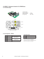
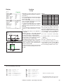
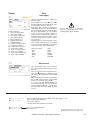
2.3 EAIO - Extension board for analogous in- and outputs
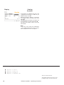
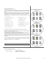
2.3.1 Board design
Technical Data:
Power consumption:
Operating temp.:
Storage temp.:
10.1 VA
5°C...40°C
-30°C...60°C
Pin position
1
10 21
30
11
20 31
40
The EAIO-board is an extension board for analogous
inputs and outputs. It can be attached to the I/O
controller board at any of the four sockets and will
be recognized by the IOC due to a self test.
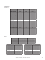
There are several jumpers on board - five for each
input - which serve to adapt the board to different
sensor types.
How to use the Jumper setting table:
- Choose the analogous input at which you have
connected a sensor.
- In the same line you can see the jumpers which
relate to this input.
- In the lower part of the table you can read in
each column the jumper setting depending on
the sensor type you connected.
Example:
You have connected a PT100 at AIN 8. The
corresponding jumpers are 301-304, 300. Jumper
301,303,304 must be set on position 2-3, Jumper
300 on 1-2 and Jumper 302 not at all.
AIN 9
AIN 8
AIN 7
AIN 6
12
Jumper 101-404
(enlarged section)
Table: Jumper setting
Jumper designation
Analogous
input
corresp.
input
AIN 6
101
102
103
104
100
AIN 7
201
202
203
204
200
AIN 8
301
302
303
304
300
AIN 9
401
402
403
404
400
Connected sensor type at anal.
input
Jumper 100-400
(enlarged section)
0-10V
1-2
2-3
1-2
1-2
0
4-20mA
1-2
1-2
1-2
1-2
0
PT100
2-3
0
2-3
2-3
1-2
PT1000
2-3
0
2-3
2-3
2-3
InRoom Controller - Operating Instructions
2.3.2 Assignment - EAIO
The assignment depends on the unit version (DX1, DX2, CW). For more information, see „2.1.2 Assignment - I/O Controller“
on page 7.
Pin Designation
1
+Ub/Ib
2
Ain 6
3
GND
4
GND
5
+Ub/Ib
6
Ain 7
7
GND
8
GND
9
+Ub/Ib
10
Ain 8
11
GND
12
GND
13
+Ub/Ib
14
Ain 9
15
GND
16
GND
17
Aout 5
18
GND
19
Aout 6
20
GND
21
Aout 7
22
GND
23
Aout 8
24
GND
X10 SUB-D 15
DX1
DX2
CW
Universal sensor 4
Outside temperature
Universal sensor 4
Outside temperature
Universal sensor 4
Outside temperature
Universal sensor 5
Condensation pressure
Universal sensor 5
Condensation pressure 1
Universal sensor 5
Water temp. 2 (CW2)
Universal sensor 6
Evaporation pressure
Universal sensor 6
Condensation pressure 2
Universal sensor 6
- free -
Universal sensor 7
Water temp. (G)
Universal sensor 7
Water temp. (G) or evaporation pressure 1
Universal sensor 7
- free -
Suction valve / compressor1 or actual humidity
Suction valve / compressor1 or actual humidity
Actual humidity
Actual temperature
Suction valve /
compressor 2/ act. temp.
Actual temperature
HWR valve
HWR valve
HWR-valve
EEV (with 0-10V) or pro- EEV (with 0-10V) or proportional dehumidification portional dehumidification
Bus 3 I2C (plug)
Bus 3 I2C (plug)
InRoom Controller - Operating Instructions
Proportional
dehumidification
Bus 3 I2C (plug)
13
2.4 EBUS - Extension board for 2x RS485 bus
2.4.1 Board design
Technical Data:
Power consumption:
Operating temp.:
Storage temp.:
11.3 VA
5°C...40°C
-30°C...60°C
JP1
Port 2
Port 3
JP2
2.4.2 Assignment - EBUS
Termination jumper
14
Pin
Designation
1
Port 2-H
2
Port 2-L
1
Port 3-H
2
Port 3-L
X10
SUB-D 15
Function
RS485 BMS-bus
Jp n°
Function in position 1-2
1
EBUS Port 2 termination
2
EBUS Port 3 termination
RS485 Aux-bus
(e.g. EC-motor)
Jp 1 has to be set, if the cooling unit represents
the first or last element in the BMS bus.
EBUS extension (socket)
Jp 2 has to be set, if the cooling unit represents
the first or last element in an Aux-bus.
InRoom Controller - Operating Instructions
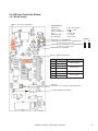
2.5 InRoom Controller Board
2.5.1 Board design
RS232 - service port (SUB-D 9)
Technical Data:
Dimensions:
Voltage supply:
Power consumption:
Fuse:
Operating temp.:
Storage temp.:
270 x 110 x 40 mm
24(+15%) VAC
14 VA
2 A time-lag
5°C...40°C
-30°C...60°C
Position
RS485 Driver for the BMS bus
B
Jumper X2: bus termination for RS 485 I/O-bus A
Pos. A: set, Pos. B: not set
Jumper X3: bus termination for RS 485 BMS-bus
Pos. A: set, Pos. B: not set
RS485 Driver for the IO bus
X4
X12
CPU
Realtime
clock
Pin
14
13
12
11
10
9
8
7
6
5
4
3
2
1
RS232 - BMS port (SUB-D 9)
Pin
Designation
14
Port 2-L
13
Port 2-H
12
Port 1-L
11
Port 1-H
10-3
Free terminal
2
GND
1
+24VAC
Function
RS485 BMS-bus
RS485 I/O-bus
none
Power supply
Fuse T1A
Jumper X6: Pos. A: Board in download mode
Contrast adjustment for display
InRoom Controller - Operating Instructions
15
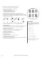
3. Operator interface
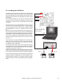
3.1 I/O Controller
A keyboard is used to operate the I/O controller by using
specified commands that follow an easily understood
syntax.
To establish the connection from a PC to the IOC a 9-line
cable with SUB-D 9 connectors at both ends (crossed
type), which can be obtained as an option, is needed.
A terminal program is also needed. You can download
the terminal program "Service" from the APC website
www.apc.com. Connect the cable at a serial port of
your PC and at the service port X15 on the IOC. Start
the terminal program.
You can now communicate with the connected I/O controller (ioc), and in return the IOC sends the following
prompt to your PC:
"ioc ##:>", where ## represents the bus id.
The commands can be classified into three major categories:
1. Bus specific control commands
2. Commands related to cooling unit components
3. Commands concerning the whole cooling unit
1. Bus command
invite ##
del ##
iobus
checkbus
spreadbusconf
2. Component command
sensor 1
comp 1
suctionv 1
gecwv
gvalve
drycool 1
pump 1
eheat 1
gasheat
pwwheat
humi 1
dehumi
fan 1
louver 1
Each command displays a detailed help for further
parameters (if there are any) when it is followed by "h"
such as "comp h".
A command of the second (component command) or
third category (Cooling unit command) which is typed
in without any parameters displays all the information
about its subject (except "loaddefault ###" which is an
execution command).
16
3. Cooling unit command
equip
is 1
state
ups
wprg
event
log 1
option
exalarmin 1
zone 1
loaddefault dx1
The commands on a light-gray (yellow) background need
no further parameters. The commands which are followed
by a number need this number because there are several
components of the same type.
The bus commands except for „iobus“ are control commands that are executed after pressing the enter key.
The bus commands on a dark-gray (green) background
need the bus I.D.s of their respective units in order to
execute.
InRoom Controller - Operating Instructions
Now the bus commands in detail:
- The invite command plus bus I.D. adds a bus participant.
- The del command plus bus I.D. excludes the participant from the bus and sends the new I/O-bus
configuration to all participants.
- The checkbus command checks every I.D. address
from 00 to 31 for the presence of a bus participant and
updates the stored bus configuration accordingly.
- The spreadbusconf command distributes the bus
configuration to all participants.
- The iobus command edits the stored I/O-bus configuration.
General
The numbering of any digital or analogous in- or output
begins with number 1. Despite this the digital/analogous
in- or output 0 can be assigned to any component. This
will allow the component to stay part of the configuration
even if it does not take part in the control.
A double assignment of in- and outputs is not possible
with the exception of in-/output 0 and the alarm priorities
(relays).
Whenever a parameter is expressed by a logical function,
0 means no, disabled; 1 means yes, enabled.
If at unit start no valid configuration is found, the configuration for single refrigerant circuit-units DX1 is loaded.
Note that no year below 2000 can be entered.
InRoom Controller - Operating Instructions
17
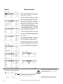
3.2 Operational elements of the InRoom Controller
Audible indicator
<>
=
Selector key
Ok
=
Confirmation key
Reset
=
Reset key
LED
=
Alarm
LED
=
On/off
=
On/off key
Display
Selector key
Selects menus and changes parameters.
Confirmation key
Acitvates the functions/parameters selected with the selector key.
Reset key
Press once to silence the alarm tone. Press a second time to clear the alarm message
(if the cause has been eliminated).
LED alarm
Lights up in the event of an alarm.
LED on/off
Lights up when the selected IOC is switched on.
On/off key
Turns off the selected cooling unit.
Audible indicator
Issues an alarm tone when an alarm has occurred.
Display
The display shows data, operating conditions and information to guide the operator.
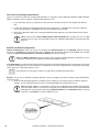
Operation - Navigation through the menus
Use the selector and confirmation keys to navigate in and across the menus.
The cursor is represented by the inverse display of field content. This field
may contain an expression, a number or a symbol.
There are two types of menus: Selection menus and parameter menus. In
selection menus you can choose a menu point using the selector key and
the confirmation key to navigate the next submenu. To get back to a higherlevel menu there is a "Return" field in the top left corner of every menu.
In parameter menus, which represent the end of a menu branch, you can
select parameters with the selector key, but if you press the confirmation
key, the parameter is displayed black on a clear background with a black
frame and indicates the change mode. Use the selector key to change the
parameter value. Pressing the confirmation key finishes the modification and
re-displays the inverse cursor.
Select „more“ in some parameter menus using the selector key to display a
new window with more information.
18
InRoom Controller - Operating Instructions
Selection menu
Parameter menu
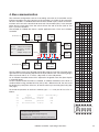
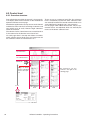
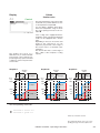
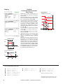
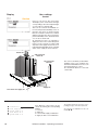
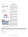
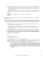
4. Bus communication
The maximum configuration consists of 16 cooling units with an I/O controller and an
InRoom Controller. One of the features of the controller is its facility for bus operation.
All that is needed is a shielded cable with two lines twisted in pairs, which are connected from unit to unit at the terminals 56-59 of each I/O controller (IOC). In the example
below the bus termination of the two units that form the end of the bus (IOC 01 and
IOC 17) must be enabled.
The example of a RS485 bus shows a typical application with 7 IOCs and 1 InRoom
Controller.
IOC
JP1 Pos.1-2!
bus ID:01
IOC
bus ID:03
IOC
bus ID:07
RS 485
IOC
bus ID:08
Bus termination:
InRoom Jumper X2 on InRoom
Controller: Controller board in
position A
IOC:
Jumper 1 in pos. 1-2
terminals
on IOC
Screen
56 57 58 59
status
passive
active
passive
active
4
5
0
0
0
0
0
0
1
1
0
0
0
0
2
0
1
0
0
0
3
1
1
0
0
0
4
0
0
1
0
0
5
1
0
1
0
0
6
0
1
1
0
0
7
1
1
1
0
0
8
0
0
0
1
0
0
0
1
0
10
0
1
0
1
0
56 57 58 59
11
1
1
0
1
0
12
0
0
1
1
0
13
1
0
1
1
0
14
0
1
1
1
0
15
1
1
1
1
0
16
0
0
0
0
1
17
1
0
0
0
1
18
0
1
0
0
1
19
1
1
0
0
1
20
0
0
1
0
1
21
1
0
1
0
1
22
0
1
1
0
1
23
1
1
1
0
1
24
0
0
0
1
1
25
1
0
0
1
1
26
0
1
0
1
1
27
1
1
0
1
1
28
0
0
1
1
1
29
1
0
1
1
1
30
0
1
1
1
1
31
1
1
1
1
1
IOC
bus ID:15
InRoom
Controller
bus ID:31
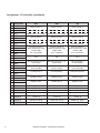
To control the presence of each bus member, type iobus and you will see a list as
follows:
type
unknown
IO-controller
unknown
IO-controller
3
1
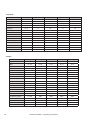
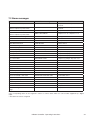
The bus address or bus ID is adjusted with the dip-switches on the IOC. The table at the
right shows the corresponding adjustment for all possible bus IDs. The counting begins
with 0 and ends with 31. A "1" means a dip-switch is in the ON position.
On an InRoom Controller the bus-ID is adjusted in the global status line (See chapter
5. Controller Start).
An IOC is delivered with the ID 01 as standard, an InRoom Controller has the ID 31 as
standard. After having provided all units (IOCs) with a different bus-ID, the units must
be declared as participants of the bus, for the bus exists up to now only physically. (See
next page).
ID
00
01
02
03
2
DIP-switch
9
LOW
IOC
bus ID:14
1
terminals
on IOC
HIGH
IOC
JP1 Pos.1-2!
bus ID:17
Bus
ID
availability
000
255
000
me
In short:
1. Connect units by bus lines
2. Set bus terminations (beginning/end)
3. Adjust bus-IDs
4. Generate bus configuration (declare participants)
InRoom Controller - Operating Instructions
19
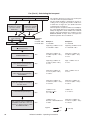
4.1 Bus with InRoom Controller + IOC
Configuration of the bus participants
1. Configure the address of the bus participants with the DIP-switches or in the global status line at the InRoom
Controller.
2. Declare the bus participants; there are 3 ways to do this:
a. Move DIP-switch 6 from ON to OFF.
b. Use the selector key to mark all units from an InRoom Controller when the bus with ID 31 is marked. Press
the confirmation key OK and enter the Service password.
c. Connect a laptop to any IOC and enter the command "invite me" or "invite ##", where ## represents
the bus-ID of the IOC to which you are connected. Then use the command invite ## with each bus-ID of
the connected elements to declare other participants.
3. Check the presence of the bus participants in the overview on the display of the InRoom Controller or by using
the command iobus.
Deleting bus participants from the bus configuration
1. Delete a bus participant by typing the command del ## .
Adding bus participants to the bus configuration
1. Adjust a free bus-ID. If the bus participant, which will be added, is an IOC, adjust the DIP-switches. If the bus
participant, which will be added, is an InRoom Controller, adjust the bus-ID in the global status line. (See „Controller start“ on page 21).
2. Declare the bus participant by using the command invite ## with the adjusted bus-ID.
Address modification of participants
1. Delete the bus participant from the configuration.
2. IOC: change the dip-switch adjustment correspondingly. InRoom Controller: change the bus-ID in the global
status line.
3. Declare the bus participant by the command invite ## with the adjusted bus-ID.
4.2 Special cases
Adding an IOC with invalid bus configuration to a consisting InRoom Controller/IOC-configuration
1. Separate the new unit with invalid configuration from the bus.
2. Delete the IOC with invalid configuration from another IOC (with valid configuration) del ##.
3. Adjust a free address with the DIP-switches at the new IOC.
4. Delete the stored bus configuration of the new IOC (either each single address with del ## or globally with
the command checkbus; this command scans the addresses and deletes every unit that is not present).
5. Connect the new unit to the bus.
6. Invite the new IOC by another IOC by typing the "invite ##" command.
General Note:
If there is data traffic on the bus, a new unit can only be invited by a valid/active bus member. A bus member is
valid/active if the TX1-LED on the IOC board is red.
20
InRoom Controller - Operating Instructions
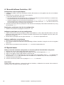
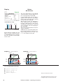
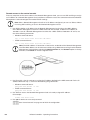
5. Controller start
After having switched on the power supply of the InRoom Controller the window
illustrated at the right will appear. This window displays the maximum number
of 32 bus participants (bus ID 0-31).
An I/O controller is displayed by a square frame containing the local temperature and humidity. A gray frame signifies that the unit is in a stop state, and
a black frame indicates that the unit is in operation. An IOC symbol without
measured values indicates that the IOC is not reachable, either because it is
switched off (no voltage) or due to a bus fault. The other symbols contain an
abbreviation for the controller type:
context status line
AT - InRoom Controller,
ME - InRoom Controller at which these windows are displayed.
The bus-ID can be deducted from the location in the scheme. Line 1 contains
the bus participants 0 - 7 from left to right; line 2, 8-15; line 3, 16-23; line 4,
24-31.
A space signifies that a unit with a corresponding bus-ID does not exist.
A symbol/unit that is selected displays inversely. In the window on top of the
page the InRoom Controller is selected. It appears inversely with white letters
on a black background. In the window below, the IOC is selected.
The context status line contains the bus-ID and the global address of the
selected bus participant.
The global status line contains the bus-ID, the global address of the InRoom
Controller, and the clock.
global status line
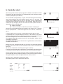
Mark the last bus participant position 31 to access the screen illustrated to
the right. The entire system can be switched off in this state by using the local
on/off key.
All units are switched on and off by pressing the on/off key.
If you press the OK-button when all positions are marked the checkbus function
is carried out (after the request and entry of the service master password).
Use the selector key to navigate to the bus-ID of the InRoom Controller which
can be adjusted (after the request and entry of the service master password).
The global address cannot be adjusted here, for safety reasons.
The time can be adjusted by selecting the clock.
The following items can be adjusted in sequence:
bus-ID
global address
- Year
- Month
- Day
- Hour
- Minute
- Second
InRoom Controller - Operating Instructions
21
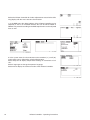
Select the InRoom Controller for further adjustments to receive the following display with the menu structure shown below.
1. In the BMS menu the global address of the InRoom Controller can be
adjusted as well as an available interface that can be either RS232 or
RS485. The protocol according to the BMS requirement can be adjusted
here as well.
3. In the system menu, the alarm buzzer can be turned on (-1-) or off (-0-)
and its pitch can be adjusted by selecting Buzzertone.
Select Temp.unit to display temperature readings in Fahrenheit or Celsius.
Select Languages to change the operator language.
Select Info to display the software version of the InRoom Controller.
22
InRoom Controller - Operating Instructions
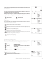
If you select an I/O controller the main menu will display as illustrated to the
lower right with the option to choose one of the three submenus "Info", "Control" or "Service".
This menu screen displays the control type (Room or Supply air) and the corresponding actual values of the control type.
Below the actual values is a symbol that indicates whether the unit operates
during the day or night. Day operation corresponds to operation at the first
setpoint temperature. Night operation corresponds to operation at the second
setpoint.
Day operation
Night operation
Stop states
The I/O-controller can be stopped by several functions or devices, which are
displayed on the InRoom Controller.
Indicates that the IOC has been stopped.
Stopped by remote On/Off (remote switch connected to digital input 10).
Stopped by PC (by BMS program).
Stopped by internal timer (week program).
Stopped by the on/off-key at the InRoom Controller or by the command
"state stop" using the IOC service port.
Stopped by the sequencing.
Symbols for operating states
When the control is in operation, the following symbols indicate the unit status
on the main menu. These symbols are not displayed in the submenus.
Cooling
Heating
Humidification
Dehumidification
Parameter values
Instead of numerical values two other displays
are possible:
1. ??? - value requested at the IOC, without
response yet.
2. XXX - component not configured.
Symbols for alarm messages
When an alarm has occurred the following symbol is displayed in the
left bottom corner of the menu screen.
InRoom Controller - Operating Instructions
23
Passwords
To access the Control level and the Service
level a password is required.
There are four passwords total, a user-specific
password for both the Control- and Service
level and a master password for each level.
The default user-specific password is „0000“
for both levels. It can be modified.
The master passwords are for service staff
only and give them authorization to adjust the
bus-ID and to execute the checkbus function
at the InRoom Controller.
Entering the password
Use the selector key to change the digits in the
password. After the digit adjustment confirm
with the confirmation key and use the selector
key to move to the next digit.
When you have reached the last digit in the
password, you access the main menu of the
Control or Service level by pressing the selector key ">".
There is no limit on password attempts.
24
InRoom Controller - Operating Instructions
6. Operation
6.1 Info level
6.1.1 Info commands
Generally each component- or cooling unit-command that is entered without parameters only displays information
without changing adjustments. However, the following commands give a general overview about the unit state and
configuration.
equip state is 1 is 2 is 3 -
Shows the components and their numbers and the extension cards (digital/analogous).
Shows the unit and functional (cooling, heating etc.) runtimes and the unit/component state.
- Setpoints, actual zone/unit values, limit values.
- Alarm delay, priority, common alarm assignment for each limit value alarm.
- Control type, sensor limitation values, cooling priority, winter operation, UPS mode, outside temperature for condensation pressure reduction, gradient for pressure reduction, winter start delay, bus/global
address, temperature difference for overload activation, last service, service interval.
- Assignment of in/outputs: common alarm, winter operation, remote on/off, UPS operation, actual
temperature/humidity, CW cooling off.
wprg Shows the programmed timer function for the week.
events - Shows all registered events (maximum 200, alarms & unit on/off).
ups Shows the UPS (uninterrupted power supply) configuration.
InRoom Controller - Operating Instructions
25
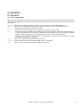
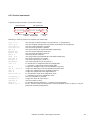
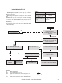
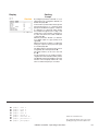
6.1.2 Info overview
A
B
26
InRoom Controller - Operating Instructions
A
B
InRoom Controller - Operating Instructions
27
Display
Data logger
Info
Use the data logger to save measured
values or average values (zone data)
calculated by the controller and have
these values displayed in the shape of a
graphical curve so as to show their time
course.
Values of two different sensors can be
simultaneously recorded.
You set the lapse of time which will be
displayed. Further parameters (type of
measured value and cycle) can be adjusted in the service menu.
You can choose among 5 different lapses
of time: hour (adjusting this lapse displays
the recent 3 hours), day, week, month
and year.
The time lapse is displayed in a horizontal
direction; a vertical dashed line marks the
actual time.
The range of the measured value within
the limit values (if existant for this type of
value) is displayed vertically.
Two exterior dashed lines mark the limit
values. An interior dotted line marks the
set value, if existant.
The course of the measured value is displayed by a continuous line.
The corresponding commands:
log 1
log 1 1
For data logger 1 each
- Displays adjustments, number of data and date
of recent and eldest value.
- Displays the 20 recent values as follows.
Type.............:1 (Unit room temp)
Store cycle......:15 Min
Number of values.:938
Youngest.........:11.08.2004 15:33:00
Eldest...........:01.08.2004 02:18:00
0001. 11.08.2004 15:33:00 Room temperature 22.9°C
0002. 11.08.2004 15:18:00 Room temperature 23.0°C
0003. 11.08.2004 15:03:00 Room temperature 23.1°C
log 1 2
log 1 72
- Edits 20 values before the last 20 values (value
21 to 40 going from the actual point of time).
- Edits the eldest 20 values (value 1421 to 1440
going from the actual point of time).
log 1 15.05.2006 - Edits all values of this day as far as stored.
log 1 1 13
log 1 clear
28
- Edits the values 1 to 13 going from the actual
point of time.
- Deletes all stored values.
InRoom Controller - Operating Instructions
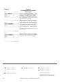
Display
Info
Current values
This window shows the actual values of the
connected sensors the same as the setpoints
adjusted at the controller.
The setpoints shifted by the controller (CORR.)
are also displayed. These setpoints are due to
the week cycle program (see page 72) or by
the sensor limitation control (see page 69). The
shifted setpoints are priority setpoints.
Here you can see the measured values for the
zone. These values represent an average value
for each parameter, which is calculated from all
sensors of the units which are assigned to the
same zone.
These are the measured values for the unit.
These are several sensor values of the unit.
InRoom Controller - Operating Instructions
29
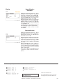
Display
Module state
Info
InRoom Controller gives a detailed representation of the operating states of the
components.
In the following windows you can see the
operating state of each component:
-0- means component is off.
-1- means component is on.
xxx means component does not exist.
This window displays the opening degree
of the valves in a percentage from 0 to
100.
If your cooling unit is equipped with a
heater, the operating state is displayed in
this window. For proportional heaters the
actual capacity is shown from 0-100%.
For the hot water reheat the actual capacity is displayed in the shape of the
opening degree of the HWR valve.
On/off state of the dry coolers
On/off state of the pumps + actual capacity
in %, if the pumps are speed controlled.
If your cooling unit is equipped with a humidifier, the operating state and the degree
of steam production of the humidifier is
displayed in this window.
In addition the display indicates whether
the dehumidification is switched on or
off.
The operating state of the fans with the
actual speed from 0-100% is indicated in
this window. If your cooling unit is equipped
with louvers, -1- indicates that the louver
is open.
This table shows digital and analog inputs/outputs and displays 0 or 1 for each
digital input/output, which could be helpful
for diagnosis purposes.
In the first line the inputs from 1 to 4 are
displayed, in the second line the inputs
from 5 to 8 etc.
D-IN
D-OUT
A-IN
A-OUT
30
InRoom Controller - Operating Instructions
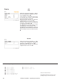
Display
Signification
1
voltage present -> no
alarm
1
relay activated -> component in service
0-4095
0-20mA, 4-20mA, 0-10V
corresp. to sensor type
0-4095
0-10V
Display
Info
Runtimes
The runtimes of the listed components
are shown in hours in the following windows at the bottom of the page.
The functional runtimes in detail:
The unit runtime comprises all times when
at least one component is operating.
The stoptime is counted when the unit is
in local stop or timer stop or remote stop
or bms-stop.
The cooling runtime is counted each time
that cooling is requested.
The heating runtime is counted each time
that heating is requested.
The humidification runtime is the total
runtime of all humidifiers.
The dehumidification runtime is counted
each time the solenoid valve for cutting a
part of the evaporator is activated/closed
or the fan speed is reduced for dehumidification reasons (DX-size 1 and all
CW-units).
Event-Log
All alarm messages and events of one
cooling unit are listed in this window. The
messages contain the following information: alarm text, day and time.
When the unit was started and stopped
is also displayed.
Up to 200 events can be stored.
System
In this menu the software version, the
hardware version and the unit type are
displayed.
The field "more" shows that there is another window.
Here the number of connected EAIO-,
EDIO- and EBUS-boards is indicated, the
same as optional extensions of the software.
InRoom Controller - Operating Instructions
31
6.2 Control level
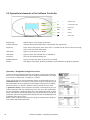
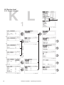
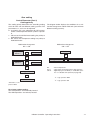
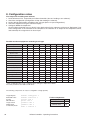
6.2.1 Overview structure
Due to limited space within the manual, it is not possible to display entire menu branches of the two different
operator interfaces on one page.
We therefore applicated a city map screen on the Control
and Service menu overview, consisting of columns and
rows which serve to easily relocate single submenus
within the overview.
The columns for the Control menu are named from A to
F, the columns for the Service menu from K to V.
On each page there is one top row without a number,
which contains the top level menu and seven rows for
the submenus which are named from 1 to 7.
There are up to 4 submenu levels.The first submenu
level is horizontally located. All other submenu levels
are vertically located. The second submenu level on an
arrow indicates the beginning of a new submenu.
On the pages which follow the overview, only the parameter menus are explained, which are normally the
menus of the lowest submenu level.
top level menu
1st submenu level
sector A2
47
page, on which
there is a detailed
menu description
sector
The submenus can also
continue to the right on the
following page.
4th submenu
level
3rd submenu
level
2nd submenu
level
A2
32
InRoom Controller - Operating Instructions
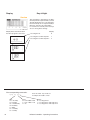
6.2.2 Control commands
A typical control command is structured as follows:
top command
sub-command
drycool 1 startsum 32.0
command component parameter
number designation
parameter
value
Following a summary of the most frequent sub-commands:
type 1/2/3..
start #,#
startsum #,#
startwin #,#
hys #,#
hyssum #,#
hyswin #,#
press #
grad #,#
pretime #
preopen #
prespeed #
conf 0/1
ain #
din # / alarm #
aout #
dout #
basicalarm 0/1
alarmdelay #
alarmprio #
runtime #
hand 0/1
handon 0/1/#
sets the type of control (mostly 1=2-point control, 2 = proportional)
sets the startpoint (temperature or humidity according to the component)
sets the summer operation startpoint
sets the winter operation startpoint
sets the hysteresis (for on/off-controlled components)
sets the summer operation hysteresis
sets the winter operation hysteresis
sets the pressure startpoint
sets the gradient (for proportionally controlled components)
sets the pre-start time in seconds
sets the pre-opening of a valve in %
sets the pre-speed of a fan or pump in %
0 = deactivates a component from the configuration
1 = activates a component for the configuration
assigns the analogous input # to the component (sensor)
assigns the digital input # to the component related alarm
assigns the component to the analogous output #
assigns the component to the digital output #
0 = no common alarm when component alarm
1 = common alarm when component alarm
sets the alarmdelay in seconds
assigns the alarm to alarm relay #
sets the runtime in hours
0 = disables manual operation, 1 = enables manual operation
0/1/# = switches off/on the component in manual operation or sets a value in % for proportionally controlled components
InRoom Controller - Operating Instructions
33
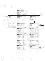
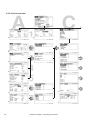
A1B C
6.2.3 Control overview
36
37
38
39
40
41
42
43
34
36
2
3
4
5
6
7
1
2
3
4
52
52
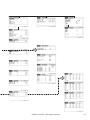
InRoom Controller - Operating Instructions
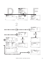
53
D1E F
53
2
3
4
5
6
7
53
1
44
E-heating 2
E-heating 3
E-heating 4
2
45
3
48
49
Fan 2 54
Fan 3
52
Louver 2
Louver 3
Humidifier 2
Humidifier 3
44
44
4
52
InRoom Controller - Operating Instructions
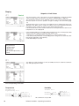
35
Display
A1
Setpoint & Limit Values
Control
The first two items of the control menu concern the adjustment of setpoints and limit
values. The limit values are decisive for the alarms "temp/humidity too high/low".
Two temperature setpoints can be adjusted, setpoint 1 concerns the operation by day,
whereas setpoint 2 concerns operation at night according to the week timer (page
72).
The limit values for the room air sensor, the supply air sensor, and the water sensor are
displayed. The "MIN" column contains the values for the lower temperature limit and
the "MAX" column contains the values for the upper temperature limit.
If the measured value is lower than the minimum room air temperature, the alarm "Room
temperature too low" is displayed.
In the following window you can adjust three parameters for the room temperature limit
alarms and for the supply air temperature limit alarms each.
1. Whether the corresponding alarm shall release a common alarm (1=yes).
2. The alarm priority, where the corresponding alarm is assigned to an alarm relay with
this number (adjusted as alarm priority).
3. The alarm delay in seconds.
For the water limit alarm the following parameters:
- Common alarm
- Alarm priority
- Alarm delay
can only be adjusted by commands.
B1
You adjust the same parameters for the air humidity. However no difference between
day- and night-setpoint is made.
The corresponding commands:
Temperature
Humidity
settemp 24.3
nightsettemp 27.0
sethumi 45.1
mintemp
maxtemp
36
room
supply
water
temp 15.0
alarmprio 8
alarmdeleay 4
commonalarm 1
minhumi
maxhumi
All combinations are possible.
InRoom Controller - Operating Instructions
room
supply
humi 3.0
alarmprio 8
alarmdelay 4
commonalarm 1
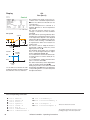
Display
Cooling
A2
Comp.
Compressor (part 1)
Control
➋a
➊a
ON
OFF
T/°C
setpoint
➊
➋
The start temperature for the compressor
is entered as a positive difference to the
setpoint.
Two different start temperatures + hysteresis for summer and winter operation can
be entered. (➊,➊a,➋,➋a)
The compressor pause is entered in seconds and serves to increase the service
life of the compressor by delaying the
restart by the adjusted value. ➌
You can adjust, whether the compressor
alarm releases a common alarm (0= no,
1 = yes) ➍ and, whether the low pressure
alarm releases a common alarm. ➍a
The compressor alarm delay can be
adjusted the same as the low pressure
alarm delay. ➎,➎a
Setting the priorities for the compressor
alarm ➏ and the low pressure alarm
➏a means assigning the corresponding
alarm to an alarm relay with the adjusted
number.
The corresponding commands:
➊
➊a
➋
➋a
➌
➍
➍a
comp
comp
comp
comp
comp
comp
comp
1
1
1
1
1
1
1
startsum 0.6
hyssum 0.7
startwin 1.2
hyswin 0.7
pause 180
commonalarm 1
commonalarmlp 1
➎
➎a
➏
➏a
comp
comp
comp
comp
1
1
1
1
alarmdelay 5
alarmdelaylp 5
alarmprio 1
alarmpriolp 1
InRoom Controller - Operating Instructions
Times are entered in seconds.
The numbered callouts refer to the corresponding passages in the descriptive text.
37
Display
Cooling
A2
Control
Compressor (part 2)
The low pressure alarm can be managed
in a way to avoid a premature and unnecessary service intervention.
If the LP switch releases, the compressor
is stopped and restarted after the compressor pause has elapsed. The LP alarm
is inhibited during the winter start delay
(see page 70).
This way the controller tries to bypass
temporary LP alarms.
You can limit the number od compressor
restarts in "RESTARTS" ➐b within a time
space which you can adjust in the first
line ➐.
If the maximum number of restarts is
reached, the LP alarm is released and
the compressor is definitely switched off.
Using the optional LP-sensor you can adjust a threshold ➐a which marks the lower
limit for the permissible pressure range.
With a HP sensor (either part of G-valve
or separate option) high pressure alarms
can be equally managed for the same
reasons as LP alarms.
You can limit the number od compressor
restarts in "RESTARTS" ➑b within a time
space which you can adjust in the fourth
line ➑.
If the threshold ➑a of the HP is exceeded the adjusted number of times, the
HP alarm is released and the measure
which you have adjusted in HP mode ➒
is taken.
0: unit off
1: unit continues operation
The corresponding commands:
➐
➐a
➐b
➑
➑a
➑b
➒
38
comp
comp
comp
comp
comp
comp
comp
1
1
1
1
1
1
1
lptime 2
lppress 4.6
lptries 6
hptime 2
hppress 21
hptries 3
hpmode 1
Times are entered in seconds.
The numbered callouts refer to the corresponding passages in the descriptive text.
InRoom Controller - Operating Instructions
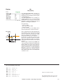
Display
Valves
A3
Control
Suction valve
The start temperature for the suction valve
is entered as a positive difference to the
room temperature setpoint. ➊
You can adjust a gradient, which determines the temperature range in which
the valve opening increases from 0 to
100%.➋
The graphics A-C show, for a
DX2-unit, how you obtain a double
proportional control range by approaching the stop point of the 2nd
compressor to the start point of the
suction valve.
Graphic A
Cool.
cap.
200%
Graphic B
Suction
valve
Comp. 1
If the cooling unit is equipped with two
refrigerant circuits, only the first refrigerant
circuit can be equipped with a suction
valve.
Depending on how you choose the start
points for the compressors you can
exploit the proportional control range of
the suction valve to a maximum. (See
examples.)
The suction valve has a control range of
50% - 100% of the compressor cooling
capacity.
Comp. 1
Comp. 2
Cool.
cap.
200%
Setpoint
Suction
valve
Graphic C
Comp. 2
Comp. 1
Cool.
cap.
200%
Setpoint
Suction
valve
Comp. 2
Setpoint
175%
Comp. 2
Comp. 2
150%
Comp. 2
100%
100%
100%
75%
75%
75%
Comp. 1
50%
Comp. 1
50%
50%
Comp. 1
➊
➋
➊
➋
➊
➋
The corresponding commands:
➊
➋
suctionv 1 start 0.2
suctionv 1 grad 0.9
Times are entered in seconds.
The numbered callouts refer to the corresponding passages in the descriptive text.
InRoom Controller - Operating Instructions
39
Display
Valves
A4
Dehumidification range
min
5
GE-CW valve
Control
max
10
14
GE-off
20
24 °C
water temp.
On the InRoom Controller you can
adjust the water temperature limits
for dehumidification here. However,
this is also possible in the dehumidification menu.
Graphic A
"close at comp = 0"
setpoint
"close at comp = 1"
setpoint
comp.
lve
va
GE
➋
➊
200%
100%
Graphic B
comp.
GE
➊
The start temperature for the GE/CW
valve is entered as a positive difference to
the room temperature setpoint. ➊
For the GE/CW valve you can adjust a
gradient, which determines the temperature range in which the valve opening
increases from 0 to 100%.➋
With the GE-off value you determine a
water temperature which establishes
the limit for GE-operation. If this value is
exceeded, the GE-operation is switched
off by closing the valve and stopping the
glycol pump. ➌
The actual water temperature is shown for
a better orientation.
Additionally you can prevent mixed operation of Freecooling and compressor cooling by setting the "Close at comp" value
to "1". (see Graphics below). ➍
lve
va
➋
200%
comp.
100%
GE valve
comp.
GE valve
comp.
The corresponding commands:
➊
➋
➌
➍
gecwv
gecwv
gecwv
gecwv
1 start 0.2
1 grad 0.9
off 22
compoff 1
Times are entered in seconds.
The numbered callouts refer to the corresponding passages in the descriptive text.
40
InRoom Controller - Operating Instructions
Display
A5
Valves
Control
G-valve
The pressure setpoint is entered in the 2nd
line and relates to the refrigerant condensation pressure in the condenser. ➊
The pre-start serves to provide a sufficient
flow for the heat absorbing medium and to
pre-cool the heat absorbing medium. When
compressor operation is requested, the
G-valve opens and the compressor start is
delayed by the pre-start time. ➋
The pre-open value is the G-valve opening
which should be obtained during the prestart time. ➌
To avoid a constant discrepancy from the
set value there are three parameters, which
imitate the behavior of an integral control.
The control factor ➍ is the decisive value, by
which the extent of the control correction is
adjusted in the way of calculating the actuating variable after the lapse of an adjustable
control cycle ➎ (0-10 sec) according to the
following formula:
Snew = Sold - f • (set value - actual value)
S: actuating variable - in this case, valve
opening
f: control factor
Set value: condensation pressure
To avoid a drastical change you can adjust
a maximum control correction ➏ (0 - ±10%).
This control correction relates to the old
actuating variable in each cycle.
The corresponding commands:
➊
➋
➌
➍
➎
➏
gvalve
gvalve
gvalve
gvalve
gvalve
gvalve
press 18.4
pretime 15
preopen 40
fact 2
concyc 5
maxc 5
Times are entered in seconds.
The numbered callouts refer to the corresponding passages in the descriptive text.
InRoom Controller - Operating Instructions
41
Display
Cooling
A6
Drycooler
Control
The start temperature for the drycooler is
entered as an absolute value for the water
temperature.
Two different start temperatures for summer and winter operation + hysteresis can
be entered. ➊,➋,➌
Note:
The summer/winter operation depends
on the setting in the menu Service/General settings/control/parameters. (see
page 70)
Drycooler
➌
➌
ON
OFF
➊
➋
winter
operation
summer
operation
T/°C
water
temp.
You can determine, whether the drycooler
alarm shall generate a common alarm
(0 = no, 1 = yes). ➍
The drycooler alarm delay can be adjusted. ➎
Setting the priority for the drycooler alarm
➏ means assigning the alarm to an alarm
relay with the adjusted number.
The parameters:
- control factor ➐
- control cycle ➑
- max. control correction ➒
- pre-speed ➓
are only necessary for the GEp-control,
which is explained in a separate manual.
The corresponding commands:
➊
➋
➌
➍
➎
➏
42
drycool
drycool
drycool
drycool
drycool
drycool
1
1
1
1
1
1
startwin 15.0
startsum 32.0
hys 3.0
commonalarm 1
alarmdelay 3
alarmprio 3
➐
➑
➒
➓
drycool
drycool
drycool
drycool
1
1
1
1
fact 3
concyc 10
maxc 4
prespeed 100
InRoom Controller - Operating Instructions
Times are entered in seconds.
The numbered callouts refer to the corresponding passages in the descriptive text.
Display
Cooling
A7
Pump
Control
Depending on which pump type you have
configured, different parameters are decisive.
(See table 1).
The start temperature for the pump is entered
as a positive difference to the room temperature setpoint. ➊
The corresponding hysteresis for the pump
stop is only valid for pumps with on/off-control
such as the glycol pump.➋
For speed controlled pumps you can adjust
a gradient, which determines the range in
which the pump speed increases from 0 to
100%.➌
You can determine, whether the pump alarm
releases a common alarm (0= no, 1 = yes).
➍
GE-pump
Pump
speed setpoint
100%
0%
➊
➌
T/°C
Glycol-pump
Pump
➋
ON
OFF
➊
The pump alarm delay can be adjusted in
seconds. ➎
Setting the priority for the pump alarm ➏
means assigning the corresponding alarm to
an alarm relay with the adjusted number.
The pressure setpoint is entered in the 1st
line and relates to the refrigerant condensation pressure in the condenser. ➐
The pump pre-start serves to pre-cool the
heat absorbing medium. When compressor
operation is requested, the G-pump starts
and the compressor start is delayed by the
pump pre-start time. ➑
The pre-speed is the G-pump speed which
should be obtained during the pre-start
time. ➒
Table 1
Pump type
G (1) GE (2) Glycol (3)
Start temp.
➊
Hysteresis
Gradient
Press. setpoint
Pre-start
Pre-speed
➊
➋
➌
➐
➑
➒
The control factor ➓ a is the decisive
value, by which the extent of the control
correction is adjusted in the way of calculating the actuating variable after the lapse
of an adjustable control cycle ➓b (0-10
sec) according to the following formula:
Snew = Sold - f • (set value - actual value)
S: actuating variable - in this case pump
speed
f: control factor
Set value: condensation pressure
To avoid a drastical change you can adjust a maximum control correction ➓c (0
- ±10%). This control correction relates to
the old actuating variable in each cycle.
T/°C
setpoint
The corresponding commands:
➊
➋
➌
➍
➎
➏
pump
pump
pump
pump
pump
pump
1
1
1
1
1
1
start 0.1
hys 0.7
grad 0.6
commonalarm 0
alarmdelay 6
alarmprio 3
➐
➐a
➑
➒
➓a
➓b
➓c
pump
pump
pump
pump
pump
pump
pump
1
1
1
1
1
1
1
press 18.4
speed 96
pretime 5
prespeed 60
fact 2
concyc 5
maxc 5
InRoom Controller - Operating Instructions
Times are entered in seconds.
The numbered callouts refer to the corresponding passages in the descriptive text.
43
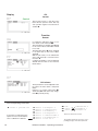
Heating
Display
F3 F5 F6
Control
On/Off-control
Heating
➋
ON
OFF
setpoint
T/°C
➊
E-heating/Hotgas reheat/Hot
water reheat
Illustration 1
Depending on which heating type you
have configured, different parameters
are decisive.
The start temperature for every heating
type is entered as a negative difference to
the room temperature setpoint. ➊
The hysteresis for the heating stop is only
valid for heatings with on/off-control.➋
For proportional e-heatings/hot water
reheats you can adjust a gradient, which
determines the temperature range in
which the heating capacity increases from
0 to 100%.➌
You can determine, whether the e-heating
alarm releases a common alarm (0= no,
1 = yes). ➍
The e-heating alarm delay can be adjusted in seconds. ➎
Setting the priority for the heating alarm
➏ means assigning the corresponding
alarm to an alarm relay with the adjusted
number.
Only the first heating can be proportional.
If this is the case and if there are several
heatings (up to 4), only the start value
and the gradient of the first heating are
decisive for the control. Each time the proportional heating reaches 100% heating
capacity another reheat is added and the
first heating is reset to 0%. This way up to
four individual heatings act as one proportional heating. (See illustration 1).
Added heat capacities
setpoint
on
3rd reheat
off
on
2nd reheat
off
100%
1st reheat
0%
300%
total
➌ ➌ ➌
➊
200%
100%
0%
T/°C
Proportional
Heating
100%
setpoint
0%
➊
➌
T/°C
The corresponding commands:
➊
➋
➌
➍
➎
➏
eheat
eheat
eheat
eheat
eheat
eheat
1
1
1
1
1
1
start 0.2
hys 0.7
grad 0.9
commonalarm 1
alarmdelay 3
alarmprio 3
➊
➋
gasheat 1 start 1.3
gasheat 1 hys 0,6
➊
➋
➌
pwwheat 1 start 1.3
pwwheat 1 hys 0.6
pwwheat 1 grad 0.5
Times are entered in seconds.
The numbered callouts refer to the corresponding passages in the descriptive text.
44
InRoom Controller - Operating Instructions
Display
Humidification
E4
Humidifier
Control
On/Off-control (type 1)
Humidifier
➋
ON
OFF
%r.h.
setpoint
➊
Depending on which humidifier type you
have, different parameters are decisive.
The start humidity for every humidifier is
entered as a negative difference to the room
humidity setpoint. ➊
The hysteresis for the humidifier stop is only
valid for humidifiers with on/off-control.➋
For proportional humidifiers you can adjust
a gradient, which determines the humidity
range in which the humidifying capacity
increases from 0 to 100%.➌
You can determine, whether the humidifier
alarm releases a common alarm (0 = no,
1 = yes). ➍
The humidifier alarm delay can be adjusted
in seconds. ➎
Setting the priority for the humidifier alarm ➏
means assigning the corresponding alarm to
an alarm relay with the adjusted number.
Proportional (type 2)
Humidifier
100%
setpoint
0%
➌
➊
%r.h.
In the following window you can adjust the
three parameters: common alarm ➍a ➍b,
alarm delay ➎a ➎b and alarm priority ➏a
➏b for the conductivity alarm at 5µS and
at 20µS.
These alarma are available with the application of a conductivity measuring instrument,
which is required to control the water conductivity for Ultrasonic humidifiers.
The corresponding commands:
➊
➋
➌
➍
➎
➏
humi
humi
humi
humi
humi
humi
1
1
1
1
1
1
start 7.3
hys 9.0
grad 10.0
commonalarm 1
alarmdelay 6
alarmprio 5
➍a
➎a
➏a
➍b
➎b
➏b
humi
humi
humi
humi
humi
humi
1
1
1
1
1
1
commonalarm5 1
alarmdelay5 6
alarmprio5 5
commonalarm20 1
alarmdelay20 6
alarmprio20 5
Times are entered in seconds.
The numbered callouts refer to the corresponding passages in the descriptive text.
InRoom Controller - Operating Instructions
45
Display
Humidification
E6
Control
Dehumidification (Part 1)
The start humidity for dehumidification is
entered as a positive difference to the room
humidity setpoint. ➊
The hysteresis for the dehumidification stop
is entered in the 2nd line.➋
To avoid a feedback circle of dehumidification
and cooling, you can adjust a stop temperature, which is entered as a negative difference
to the air temperature setpoint. ➌
With a fixed hysteresis of 1 Kelvin the dehumidification is switched on again, when the
room temperature rises.
On/Off-control
Dehumidific.
➋
ON
OFF
%r.h.
setpoint
➊
Dehumidif. -Stop
Deh.
1K
ON
Adjusting the water temperature limits for
the dehumidification refers to the possibility
of dehumidifying the air by the free cooling
coil with fan speed reduction. ➍➎
If the water temperature limits are exceeded,
the controller commutes to dehumidification
by compressor operation.
See a detailed description on the next
page.
OFF
T/°C
➌
Note:
The dehumidification fan speed is adjusted
in the Air/Fan-menu.
Dehumidification range
min
5
max
10
14
GE-off
20
24 °C
water temp.
The corresponding commands:
➊
➋
➌
➍
➎
dehumi
dehumi
dehumi
dehumi
dehumi
start 7.0
hys 7.0
stop 2.0
min 4
max 10
The surrounded numbers refer to the corresponding passages in the descriptive text.
46
InRoom Controller - Operating Instructions
Dehumidification (Part 2)
There two ways of achieving dehumidification:
1. By reducing the fan speed, this is the only way of dehumidification for CW-units.
2. By shutting down a part of the evaporator with a solenoid
valve.
Dehumidification type is chosen by the controller according
to the following conditions: Fan speed reduction or compressor operation with a dehumidification valve present. The two
dehumidification types can never be applied simultaneously.
(See table 2.)
Table 2
Fan speed reduction
Dehum. valve
A, G, ACW, GCW, GE
units without dehum. valve
(e. g. cabinet size 1)
ACW, GCW, GE units in
mixed op. and 100% free
cooling
A,G units
ACW, GCW, GE units
in 100% compressor
operation
CW units
The decision processes of the controller are displayed in detail
in the scheme below.
Start
A/G
Start compressor 1
Can the air be dehumidified by the
water temperature ?
Is a GE/CW-valve or a pump
configured ?
N
Y
GE1/GE2
ACW/GCW
CW/CW2
Does the compressor run and is
the GE/CW-valve closed or the
pump switched off ?
Y
N
Is a dehumidification valve
configured ?
N
Tw is supposed to be
okay.
Is a water temperature sensor
configured ?
Y
Y
N
Cooling priority
Y
0 (GE)
1(CW)
Y
Y
N
2(DX)
Is Tw < TRTset
and Tw < TGEoff
and Twmin < Tw < Twmax ?
Y
Y
Fan speed is reduced by "DEHUM
SPEED".
Dehumidification
valve is closed.
GE/CW-valve is opened 100%.
GE-pump runs with 100% speed.
Fan speed is reduced by "DEHUM
SPEED".
GE/CW-valve is closed.
no dehumidification
Legend:
Tw
TRTset
TGEoff
Twmin
Twmax
- Water temperature
- Room temperature set point
- upper water temperature limit for GE-operation
- lower water temperature limit for dehumidification
- upper water temperature limit for dehumidification
Y
N
yes
no
InRoom Controller - Operating Instructions
47
Display
Air
D5
Control
Fan (Part 1)
The maximum fan speed can be set in accordance to the calculated required airflow.
➊➋ For the distinction DX/CW see the
overnext page.*
The start temperature is entered as a
negative difference to the air temperature
setpoint. ➌
The start fan speed is entered as a percentage of reduction from the maximum
Fan speed
speed. ➍
This reduced fan speed is gradually obtaisetpoint
ned with a decreasing temperature from the
room temperature setpoint to the adjusted
temperature difference ➌ below the setpoint.
➍
➊ or ➋
However, when heating or humidification
+➎
is requested, the airflow is increased to its
original value.
➌
T/°C The offset is used to adapt the airflow to
heating
unexpected conditions on the site ( lower/
start
higher pressure loss).➎
The minimum speed, which you can adjust
Humidif.
here, can only be bypassed by the adjusthumidity
ment in "REDUCE SPEED". ➏
setpoint
You can determine, whether the airflow failuON
re alarm releases a common alarm (0= no,
1 = yes). ➐
You can determine, whether the filter alarm
OFF
starts a common alarm. ➐a
%r.h.
The airflow alarm delay can be adjusted the
humidif.
same as the filter alarm delay. ➑,➑a
start
Setting the priorities for the airflow alarm ➒
*In the InRoom Controller the CW- and the filter alarm ➒a means assigning the
maximum speed is actually located in corresponding alarm to an alarm relay with
the adjusted number.
the sixth line of the second menu.
The corresponding commands:
➊
➋
➌
➍
➎
➏
➐
➐a
48
fan
fan
fan
fan
fan
fan
fan
fan
1
1
1
1
1
1
1
1
nmax 85
nmaxcw 90
start 3
speed 15
offset -5
min 60
commonalarm 1
commonalarmfi 1
➑ fan 1 alarmdelay 6
➑a fan 1 filteralarmdelay 6
➒ fan 1 alarmprio 3
➒a fan 1 filteralarmprio 4
Times are entered in seconds.
The numbered callouts refer to the corresponding passages in the descriptive text.
InRoom Controller - Operating Instructions
Air
Display
D6
Control
Fan start phase
100%
nmax
➊
➋
fan
start
control
start
t/sec
compon.
start*
Fan (Part 2)
With the parameter "START 100%" ➊ you
adjust a time which must elapse before the
control begins. This way an airflow alarm is
avoided which could occur due to the fan
inertia. During this time the fan is operated
with 100% speed.
Using the "PRERUN" parameter ➋ you
adjust the delay for the inhibited start of
all components, except the glycol pump, in
relation to the control start with alarm monitoring. This way the Pre-run parameter has
the effect of a cooling unit start delay. Using
different pre-runtimes for different units
saves power and ensures that the power
supply of the building will not overcharge.
The fan over-run time ("HUNTING TIME")
➌, which you can adjust, serves to reject
hot or cold air in the cooling unit and avoids
an accumulation of heat at the reheat or of
cold at the evaporator.
If during a time which you adjust with "REDUCE TIME" ➍ no action (cooling, heating,
humidification, dehumidification) has been
taken, the fan speed is reduced by the pert/sec centage which you adjust with "REDUCE
SPEED" ➎.
The "FILTER OFFSET" ➏ is entered as a
positive difference to the maximum speed.
If a filter alarm is released, the maximum
%
speed will be increased by the filter offset
100
in order to overcome the higher resistance
of a clogged filter.
90
*start of all other control-relevant components
except the glycol pump, which can be started
earlier.
Fan stop phase
➌
over-run due
to fan inertia
fan stop
unit stop
Speed levels
filter offset ➏
offset ➎a*
nMax
reduced speed ➎
80
dehumidif. speed **
70
65
UPS speed **
55
*this item refers to the previous page.
** these parameters are explained on
the overnext page.
The corresponding commands:
➊
➋
➌
➍
➎
➏
fan
fan
fan
fan
fan
fan
1
1
1
1
1
1
100 5
pre 15
after 20
redtime 30
redspeed 20
filteroffset 15
Times are entered in seconds.
(except the reducing time which is entered
in minutes)
The numbered callouts refer to the corresponding passages in the descriptive text.
InRoom Controller - Operating Instructions
49
Fan (Part 3) - Calculating the fan speed
Cooling priority
1 (CW)
2 (DX)
Are the conditions for
a malfunction changeover met for DualFluid-units ?
Are the conditions for
a malfunction changeover met for DualFluid-units ?
Y
N
CW standby management enabled?
N
N
nmax DX
Parametersetting:
Y
nmax CW
The following decision processes are used by the
controller for the fan speed calculation.
The fan speed nmaxDX or nmaxCW is chosen according to the cooling priority and the conditions for
a malfunction change-over. (For details about the
cooling priority, see page 71.)
Then four queries are passed, which use a multiplication of the speed with a factor, if positively answered.
Finally the algorithm checks whether the minimum
speed is kept and whether the conditions for the
REDUCE SPEED are kept, which can bypass the
minimum speed as the sole reduction.
0 (GE)
Example 1:
Example 2:
n = nmaxDX
n = nmaxCW
supposing: condition not ok
n = nmaxDX = 100%
supposing: condition not ok
n = nmaxCW = 90%
supposing: condition ok
n = 100% x (100% - 10%)
n = 90%
supposing: condition ok
n = 90% x (100% - 10%)
n = 81%
supp.: condition not ok
n = 81%
20%
supposing: condition ok
n = 90% x (100% - 20%)
n = 72%
supp.: condition not ok
n = 81%
30%
supposing: condition ok
n = 72% x (100% - 30%)
n = 50.4%
10%
supposing: condition ok
n = 50.4% x (100% + 10%)
n = 55.44%
supposing: condition ok
n = 81% x (100% + 10%)
n = 89.1%
condition ok
so n = 89.1%
60%
condition not ok
because n < 60%
so n = 60%
50%
condition not ok
because of dehumidification
n = 60%
supposing: condition ok
n = 89.1% x (100% - 50%)
n = 44,55%
nmaxDX: 100%
nmaxCW: 90%
nmax zone
Is Tair > Tset + EMERSTART ?
(overload service)
Are the conditions for
STARTSPEED met?
10%
Does a dehumidification request
exist with the speed reduction
DEHUMSPEED?
Does the unit run in UPS operation with the speed reduction
USV-SPEED?
Has a filter alarm occurred and
must the speed be increased by
the filter offset ?
Is the minimum speed kept ?
Can a speed reduction REDUCESPEED be made due to the nonrequest of climatic functions within
the REDUCE TIME ?
Legend:
yes
no
50
InRoom Controller - Operating Instructions
next step
Display
Air
D6
Control
Fan (Part 4)
The "DEHUM.SPEED" ➊ is entered as a
negative difference in % to the maximum
speed. This is the fan speed for the first option
of dehumidification.
The "UPS SPEED" ➋ is also entered as a
negative difference in % to the maximum
speed. When the controller receives a UPS
signal the controller will apply this reduced
speed for an emergency operation.
The parameters:
- control cycle ➌
- max. control correction ➍
- control factor ➎
are only necessary for the GEp-control,
which is explained in a separate manual.
Fan speed
Setpoint
➑
DXmax/
CWmax
➏
➐
If the cooling unit has low airflow during nominal operation, the fan speed can be raised
when the temperature setpoint is exceeded.
The fan speed increase depends on the
temperature difference to the setpoint.
For this way of cooling the room by increasing the fan speed you adjust a positive
temperature difference ➏ to the setpoint,
T/°C which represents the start point of the speed
increase.
Then you adjust a maximum speed ➑ for the
overload operation and another temperature
difference ➐ to the setpoint, which marks the
end of the proportional fan speed increase.
Having attained the second temperature
difference, the fan is operated with the
maximum speed for the overload operation.
This speed is kept even if the temperature
continues to rise.
The corresponding commands:
➊
➋
➌
➍
➎
➏
❼
❽
fan
fan
fan
fan
fan
fan
fan
fan
1
1
1
1
1
1
1
1
dehum 25
ups 35
concyc 8
maxc 2
fact 2
emerstart 0.7
emerend 2.0
emernmax 95
Times are entered in seconds.
The numbered callouts refer to the corresponding passages in the descriptive text.
InRoom Controller - Operating Instructions
51
Display
D7
Air
Louver
Control
The pre-start serves to open the louver
before the fan operation starts. This way
a fan operation against a closed louver is
avoided. ➊
Function
C6
F7
Sensor
In combination with these alarms a common alarm can be released. ➊➍
The alarm delay for the limit alarm ➋ and
for the sensor failure alarm ➎ is entered
in seconds.
The limit value alarms ➌ can be assigned
to an alarm relay as the sensor failure
alarm ➏.
With the trim offset you can calibrate the
sensor with the help of a reference thermometer. ➐
Compare the display of the PHYSICAL
VALUE with the value of the reference
thermometer.
C7
Unit alarms
Three parameters can be adjusted for the
fire alarm, the water alarm, and phase
failure.
Release of a common alarm (0/1) ➊a,
alarm delay ➋a and alarm relay assignment ➌a (named priority).
The corresponding commands:
➊ louver 1 pretime 100
If, instead of a temperature, the
expression "reset" is entered, the
sensor calibration is deleted.
52
➊
➋
➌
➍
➎
➏
➐
sensor
sensor
sensor
sensor
sensor
sensor
sensor
1
1
1
1
1
1
1
alarmprio 2
commonalarm 1
alarmdelay 7
alarmpriobr 3
commonalarmbr 1
alarmdelaybr 8
trim 22.3
➊a fire
➋a water
➌a phase
InRoom Controller - Operating Instructions
commonalarm 1
alarmdelay 7
alarmprio 8
Times are entered in seconds.
The numbered callouts refer to the corresponding passages in the descriptive text.
Display
D1
Zone
Control
The parameters:
- Start temperature ➊
- Hysteresis ➋
are only necessary for the GE2p-control,
which is explained in a separate manual.
AT-Preferences
E1
The acoustic signal which resounds in the
case of an alarm and the beep for pressing
a key can be switched off (0=off, 1= on).
The pitch of the buzzertone can be adjusted
as desired.
Further on you can adjust the temperature
display in °C or °F ➊.
The operator language ➋ can also be
selected.
Password
F1
At this menu item you can adjust the password for the control level.
The default password is „0000“.
The corresponding commands:
➊ zone 1 gestart 3.0
➋ zone 1 gehys 2.0
➌ unit c / unit f
➍ language e / language g
c for °Celsius, f for °Fahrenheit
e for English, g for German
The surrounded numbers refer to the corresponding passages in the descriptive text.
InRoom Controller - Operating Instructions
53
K1L M
6.3 Service level
6.3.1 Service overview
58
59
59
59
60
61
54
2
3
4
5
6
7
InRoom Controller - Operating Instructions
1
2
3
4
5
1
62
N1O P
2
E-heating 2
E-heating 3
62
62
3
63
2
3
4
5
6
7
64
Humidifier 2
Humidifier 3
63
Fan 2
Fan 3
64
Louver 2
Louver 3
5
66
4
65
66
67
66
InRoom Controller - Operating Instructions
55
Q1R S
2
3
4
5
6
7
68
73
73
7477
69
79
70
79
78
78
78
56
etc.
InRoom Controller - Operating Instructions
T 1U V
89
80
80
80
2
3
4
5
6
7
80
80
80
80
80
80
InRoom Controller - Operating Instructions
57
Display
Cooling
K2
Service
Compressor
In the first line you add the compressor
to the configuration by entering "1". With
"0" you disable the compressor although
all settings concerning the compressor
are kept. ➊
You can determine a digital output for the
compressor on/off signal. ➋
The digital input for the compressor alarm
can be assigned in the third line. ➌
The digital input for the low pressure alarm
can be assigned in the fourth line. ➍
The compressor runtime can be adjusted
in the last line. ➎
The corresponding commands:
➊
➋
➌
➍
➎
comp
comp
comp
comp
comp
1
1
1
1
1
conf 1
dout 3
alarm 5
alarmlp 7
runtime 10
Times are entered in hours.
The numbered callouts refer to the corresponding passages in the descriptive text.
58
InRoom Controller - Operating Instructions
Display
K3
Valves
GE-CW valve
Service
In the first line you add the suction valve
to the configuration by entering "1". With
"0" you disable the suction valve. ➊
With the parameter "A-OUT" you adjust
the analogous output of the proportional
signal for the suction valve. ➋
GE/CW-valve
K4
In the first line you add the GE/CW-valve
to the configuration by entering "1". With
"0" you disable the GE/CW valve. ➌
With the parameters "A-OUT 1" and "AOUT 2" you adjust the first and second
analogous output of the proportional
signal for the GE/CW-valve. ➍➎ Two
GE/CW-valves exist in A/C-units of the
CW2-type only.
The digital input, which receives the signal
for the commutation from output 1 to output 2, can be assigned in the last line. ➏
With the reception of the signal the
alarm message "CHILLER FAILURE" is
displayed.
G-valve
K5
In the first line you add the G-valve to the
configuration by entering "1". With "0" you
disable the G-valve. ➐
With the parameter "A-OUT" you adjust
the analogous output of the proportional
signal for the G-valve. ➑
The corresponding commands:
➊
➋
suctionv 1 conf 1
suctionv 1 aout 3
➌
➍
➎
➏
gecwv
gecwv
gecwv
gecwv
➐
➑
gvalve conf 1
gvalve aout 4
conf 1
aout1 3
aout2 4
din 17
The numbered callouts refer to the corresponding passages in the descriptive text.
InRoom Controller - Operating Instructions
59
Display
Cooling
K6
Service
Drycooler
In the first line you add the drycooler to the
configuration by entering "1". With "0" you
disable the drycooler. ➊
With the parameter "D-OUT" you determine a digital output for the drycooler on/off
signal. ➋
The digital input for the drycooler alarm can
be assigned by the "D-IN" parameter. ➌
The drycooler runtime can be set in the
last line. ➍
Note:
For the dry cooler control, the configuration
of an outside temperature sensor and a
water temperature sensor is required.
The corresponding commands:
➊
➋
➌
➍
drycool
drycool
drycool
drycool
1
1
1
1
conf 1
dout 10
alarm 5
runtime 150
Times are entered in hours.
The numbered callouts refer to the corresponding passages in the descriptive text.
60
InRoom Controller - Operating Instructions
Display
Cooling
K7
Service
Pumps
By setting the parameter "ACTIVE" on 1 you
add a pump to the configuration. With "0" you
disable the pump. ➊
In the next line you determine which type the
pump shall belong to (1 = G-pump, which
pumps the medium through the condenser
in a GE2-unit, 2 = GE-pump, which pumps
the medium through the free cooling coil in
a GE2-unit, 3 = Glycol-pump - all pumps for
G-, GE1 units which are located outside the
cooling unit). ➋
With the parameter "D-OUT" you determine a digital output for a glycol pump on/off
signal. ➌
With the parameter "A-OUT" you adjust the
analogous output of the proportional signal
for a G/GE-pump. ➍
The digital input for the pump alarm can be
assigned by the "D-IN" parameter. ➎
The pump runtime can be set in the next
line. ➏
For glycol pumps you can enable a sequencing based on time and failure. With "partner
unit" ➐ and "partner pump" ➑ you select the
number of the 2nd pump and the ID of the
unit from which this pump is controlled.
The corresponding commands:
➊
➋
➌
➍
➎
➏
➐
➑
pump
pump
pump
pump
pump
pump
pump
pump
1
1
1
1
1
1
1
1
conf 1
type 2
dout 3
aout 4
alarm 3
runtime 60
partunit 17
partpump 1
Times are entered in hours.
The numbered callouts refer to the corresponding passages in the descriptive text.
InRoom Controller - Operating Instructions
61
Display
N1
Heating
E-heating/Hotgas reheat/Hot
water reheat
Service
Setting the parameter ACTIVE to 1 adds
a reheat to the configuration. Setting this
parameter to 0 disables the reheat. ➊
In the next line you determine the reheat
type (1: reheat with on/off control, 2: reheat
with proportional control). ➋
With the parameter "D-OUT" you determine
a digital output for the reheat. As the proportional electric reheat is controlled by pulse
width modulation, the reheat receives the
control signal by the digital output. ➌
The digital input for the electric reheat alarm
can be assigned by the "D-IN" parameter.
N2
➎
The electric reheat runtime can be set in
the last line. ➏
N3
With the parameter "A-OUT" you adjust the
analogous output of the proportional signal
for the pww-valve of a pww-reheat. ➍
The corresponding commands:
➊
➋
➌
eheat 1 conf 1
eheat 1 type 1
eheat 1 dout 3
➎
➏
eheat 1 alarm 7
eheat 1 runtime 0
➊
➋
gasheat 1 conf 1
gasheat 1 dout 10
➊
➋
➌
➍
pwwheat
pwwheat
pwwheat
pwwheat
1
1
1
1
conf
type
dout
aout
2
1
5
8
Times are entered in hours.
The numbered callouts refer to the corresponding passages in the descriptive text.
62
InRoom Controller - Operating Instructions
Display
Humidification
O1
Service
Humidifier
Setting the parameter ACTIVE to 1 adds a
humidifier to the configuration. Setting this
parameter to 0 disables the humidifier. ➊
In the next line you determine the humidifier
type (1: humidifier with on/off control, 2: humidifier with proportional control). ➋
With the parameter "D-OUT" you determine
a digital output for an on/off humidifier. ➌
With the parameter "A-OUT" you adjust the
analogous output of the proportional signal
for a humidifier. ➍
The digital input for the humidifier alarm can
be assigned by the "D-IN" parameter. ➎
The humidifier runtime can be set in the
last line. ➏
Dehumidification
Setting the parameter ACTIVE to 1 adds a
dehumidification valve to the configuration.
Setting this parameter to 0 disables the
dehumidification valve. ➊
With the parameter "D-OUT" you determine
a digital output for the dehumidification (solenoid valve for partial evaporator cut-off). ➋
In the second line you can configure a hotgas bypass for the compressor by entering
a "1". ➌
When dehumidification with compressor
operation is requested, the hotgas bypass
is closed, because the maximum refrigerant
mass flow is needed for the effect of passing
under the dew point.
This is also valid for dehumidification by
compressor operation with fan speed reduction.
O3
The corresponding commands:
➊
➋
➌
➍
➎
➏
humi
humi
humi
humi
humi
humi
humi
1
1
1
1
1
1
1
conf 0
type 2
dout 11
aout 4
alarm 7
runtime 500
confcon 1
➊ dehumi confvalve 1
➋ dehumi dout 12
➌ dehumi confbypass 1
Times are entered in hours.
Configuration of a conductivity meter
by commands only.
InRoom Controller - Operating Instructions
The numbered callouts refer to the corresponding passages in the descriptive text.
63
Display
Air
P1
Fan
Service
Setting the parameter ACTIVE to 1 adds a
fan to the configuration. Setting this parameter to 0 disables the fan. ➊
In the next line you determine the fan type
(1: fan with on/off control, 2: EC-fan with
proportional speed control). ➋
With the parameter "D-OUT" you determine
a digital output for an on/off fan. ➌
With the parameter "A-OUT" you adjust the
analogous output of the proportional signal
for a speed controlled fan. ➍
The digital input for the airflow alarm can be
assigned by the "D-IN" parameter. ➎
The digital input for the filter alarm can be assigned by the "D-IN FILTER" parameter. ➏
The fan runtime can be set in the last line.
➐
Louver
P3
Setting the parameter ACTIVE to 1 adds
a louver to the configuration. Setting this
parameter to 0 disables the louver. ➑
With the parameter "D-OUT" you determine
a digital output for the louver. ➒
The corresponding commands:
➊
➋
➌
➍
➎
➏
➐
64
fan
fan
fan
fan
fan
fan
fan
1
1
1
1
1
1
1
conf 1
type 1
dout 11
aout 11
alarm 2
filteralarm 6
runtime 120
➑ louver 1 conf 1
➒ louver 1 dout 11
Times are entered in hours.
The numbered callouts refer to the corresponding passages in the descriptive text.
InRoom Controller - Operating Instructions
Display
Equipment
N6
Sensor
Service
PURPOSE:
1 - Room temperature
2 - Room humidity
3 - Supply temperature
4 - Supply humidity
5 - Water temperature 1
6 - Outside temperature
7 - Outside humidity
8 - Condensation temperature 1
9 - Condensation pressure 1
10 - Evaporation temperature 1
11 - Evaporation pressure 1
12 - Water temperature 2
13 - Condensation temperature 2
14 - Condensation pressure 2
15 - Evaporation temperature 2
16 - Evaporation pressure 2
17 - Setpoint temperature
18 - Setpoint humidity
Sensors of the purpose 8, 10, 11,
13, 15, 16 are not used up to now.
Setting the parameter ACTIVE to 1 adds
a sensor to the configuration. Setting this
parameter to 0 disables the sensor. ➊
In the next line you determine the sensor
type (1: current, 2: voltage, 3: PT100,
4: PT1000, 5: KTY81-121). ➋
The parameter PURPOSE specifies for
what the sensor is used. ➌
See list at left.
With the parameter "A-IN" you adjust
the analogous input for the proportional
sensor signal. ➍
The following 5 items serve to calibrate
the sensor. The minimum measure value
(phys. value) ➎ is assigned to the minimum output (value). ➐
The maximum measure value (phys. value) ➏ is assigned to the maximum output
(value). ➑
The unit of the adjusted measure value
depends on the sensor purpose (1-16).
The unit of the adjusted output depends
on the sensor type (1-5).
If there are more than two sensors with
the same purpose, an average value is
calculated. In the last line you can adjust
a maximum difference to the average
value.➒ If the maximum difference is
exceeded, the alarm "Sensor ## excess"
is released.
You need two water temperature sensors for:
1. GCW-units with dry coolers
Water temperature 1 is always the temperature for the CW-circuit.
Water temperature 2 is the cooling water
temperature, by which the dry coolers
are controlled.
2. CW2-units
Water temperature 1 is always the
temperature for the CW-valve which is
active, when no change-over has taken
place (no voltage at DIN 3).
Water temperature 2 is the temperature
for the second CW-valve, which is active
after a change-over.
For these sensors and for the
sensor condensation pressure (9
and 14) no average value is calculated.
The corresponding commands:
➊
➋
➌
➍
sensor
sensor
sensor
sensor
1
1
1
1
conf 1
type 3
use 5
ain 3
➎
➏
➐
➑
➒
sensor
sensor
sensor
sensor
sensor
1
1
1
1
1
minmeas -20.0
maxmeas 40.0
minout 0.0
maxout 9.0
div 20
The numbered callouts refer to the corresponding passages in the descriptive text.
InRoom Controller - Operating Instructions
65
Display
O5
Equipment
Aux. Ports/Aux. Ports
Service
You can adjust digital in- and outputs for
non-component-related alarms or messages
in this window.
In detail you can adjust the digital output for
the common alarm ➊ and for the wintermode
➋. The wintermode signal can be forwarded
to a BMS system.
You can also adjust the digital inputs for the
remote contact ➌, the fire alarm ➍ and the
water detector ➎, which creates the water
alarm and for the UPS operation ➏.
P5
O7
In the following window you can assign the
digital inputs for the phase failure alarm ➐
and for the external cooling priority ➑. (See
page 71).
You can also determine the analogous
outputs for the external use of the actual
temperature ➒ and the actual humidity ➓.
Aux. Ports/Unit alarms
In this window you can assign digital inputs
to unit alarms. The fire alarm ➍, the water
detector ➎, which creates the water alarm,
and the phase failure alarm ➐.
The corresponding commands:
➊
➋
➌
➍
➎
➏
calarm dout 7
winter dout 17
remote din 11
fire din 12
water din 8
ups din 13
➐
➑
➒
➓
phase din 19
cwoff din 16
curtemp aout 3
curhumi aout 5
The numbered callouts refer to the corresponding passages in the descriptive text.
66
InRoom Controller - Operating Instructions
Display
Equipment
P6
Aux. Ports/Aux. Alarm
Service
In the first line you can type in the alarm text
which you want to be displayed in case of
the alarm. ➊
By setting the parameter "ACTIVE" on 1 you
add an external alarm to the configuration.
With "0" you disable the ext. alarm. ➋
With the parameter "D-IN" you adjust the
digital input for the alarm signal. ➌
You can adjust, whether the external alarm
releases a common alarm (0= no, 1 = yes).
➍
Setting the priority for the external alarm ➎
means assigning the alarm to an alarm relay
with the adjusted number.
The external alarm delay can be adjusted.
➏
The corresponding commands:
➊
➋
➌
➍
➎
➏
exalarmin
exalarmin
exalarmin
exalarmin
exalarmin
exalarmin
1
1
1
1
1
1
text xxx123
conf 1
alarm 11
commonalarm 0
alarmprio 9
alarmdelay 6
Times are entered in seconds.
The numbered callouts refer to the corresponding passages in the descriptive text.
InRoom Controller - Operating Instructions
67
Gen. settings
Display
R2
Service
Control
Here you can choose the control type.
The display of the actual values changes
corresponding to the above adjusted type
of control (Room / Sup.Air). ➊
The room air control is the standard control. The temperature/humidity sensor is
placed in the return air intake and the
InRoom Controller controls in accordance
with the setpoints set in the "Control/temperature/humidity" menu. The limit values
of room air are monitored.
An external T/H sensor is required for
supply air control. The control takes place
for the room air control in accordance with
setpoints for the supply air set in the "Control/temperature/humidity" menu. The limit
values of the supply air are monitored.
Return air
T/H sensor for
return air
Height > 1.5 m
T/H sensor for
room air
The sensor should be positioned depending on the room conditions, the
thermal load distribution in the room
and selected type of control.
The maximum distance to the IOC
can be 20m.
Supply air
T/H sensor for supply air
The corresponding commands:
➊
➋
➌
➍
➎
68
control 2
lim temp 16.3
grad temp 0.6
lim humi 75.0
grad humi 0.6
Four different control types can be
chosen by entering the corresponding
number:
1: room air
2: supply air
3: room air with supply air limitation
4: supply air with room air limitation
InRoom Controller - Operating Instructions
The numbered callouts refer to the corresponding passages in the descriptive text.
See next page for explanation of the commands ➋ - ➎.
Display
Gen. settings
R2, R3
Service
Setpoint
Room air sensor
T/°C
Temperature
20,5
20
14
15
16
17
T/°C
Actual value
Supply air sensor
Example (temperature):
20.5 = 20 + 0.5 • (16 - 15)
Setpoint
Supply air sensor
T/°C
Temperature
18
17,5
21
22
23
24
T/°C
Actual value
Room air sensor
Example:
17.5 = 18 + 0.5 • (22 - 23)
Control/Parameters
Using the room control with supply air
limitation causes the control to take place
using a T/H sensor in the return air intake
and a second T/H sensor in the supply
air intake. The control takes place in the
same way as room air control, the temperature setpoint is shifted only when the
supply air temperature exceeds the start
temperature ➋. The extent of the setpoint
increase is determined by a factor which
you enter, as a gradient ➌, in the menu.
The relationship, according to which the
setpoint increase happens, is made clear
by the graph on the left side. A steep
gradient drastically corrects the failure
to meet the supply air temperature, but
has the risk that the control circuit starts
to oscillate.
With humidity control the setpoint shift
takes place in the opposite direction. If the
adjusted starting humidity ➍ is exceeded
by the measured supply air humidity, the
setpoint is reduced. You can also enter a
gradient factor ➎ for this. The relationship
is shown in the graph on the right side.
Note:
For corresponding commands, see previous
page.
Setpoint
Room air sensor
r.h/%
Humidity
50
49
68
New setpoint = old setpoint + gradient •
(start value - actual value)
72
74
r.h/%
Actual value
Supply air sensor
Example (humidity):
49 = 50 + 0.5 • (70 - 72)
The supply air control with room air limitation is based on the same control principle
as the supply-air limited room air control.
Only here the setpoint shift works in the
opposite direction, because it works on
the basis that the supply air is colder than
the return air.
If the room temperature exceeds the start
temperature entered, the temperature
setpoint is reduced.
If the room humidity drops below the
starting humidity entered, the humidity
setpoint is increased.
Setpoint
Supply air sensor
r.h/%
Humidity
50,5
50
The limit values of all four input variables
are monitored for room air control with
supply air limitation and for supply air
control with room air limitation.
- Room air temperature
- Room humidity
- Supply air temperature
- Supply air humidity
70
38
39
40
41
r.h/%
Actual value
Room air sensor
Example:
50.5 = 50 + 0.5 • (40 - 39)
InRoom Controller - Operating Instructions
69
Display
Gen. settings
R3
Control/Parameters (Part 2)
Service
The controller has the option of starting a
stand-by unit after an adjustable positive
temperature difference to the air temperature setpoint is achieved. This difference
can be adjusted by the parameter "Loadstart" ➏ . The adjustment 0.0K disables
this function.
The sequencing function is not influenced
by starting a standby-unit.
R4
The outside temperature ➊ for the commutation from summer to winter operation
is decisive for the drycooler and compressor control. With this hysteresis ➋
the winter operation changes to summer
operation.
The winter operation is also switched over
to summer operation if an outside temp.
sensor breakdown is detected. An alarm
"Outside temperature sensor defect" is
not displayed.
➋
Summer
The winter start delay ➌ inhibits the low
pressure monitoring on alarm conditions
for an adjustable time in 0-255 seconds,
which is relevant for the compressor
operation.
Winter
T/°C
➊
actual value
Sfix
dS
Svar
time
5 min.
Svar n+1 = Svar n + dS
with
dS = (Sfix - actual value ) x integral factor
sfix represents the fixed setpoint which
is adjusted in the menu Control/Temperature.
You can determine an integral factor ➍
for the air temperature control to avoid a
control discrepancy which is characteristic
for P-controllers. In this case a variable
setpoint Svar, which is recalculated every
5 minutes is decisive for the control. This
variable setpoint is calculated by adding
the setpoint alteration dS to the previous
setpoint.
The values for the integral factor can be
varied between 0 an 80%. A low value
should be used to start with in order to
prevent the control system from oscillating.
10% are recommended and can stepwise
be increased to find out the limit of safe
control.
For details of the cooling priority ➎ see
next page.
The corresponding commands:
➊
➋
➌
➍
➎
➏
70
sumwin start 16.0
sumwin hys 2
winterdelay 180
integral 10
coolingprio 1
load 2.5
InRoom Controller - Operating Instructions
Gen. setting
Control/Parameter (Part 3)
Cooling priority
The cooling priority determines the overriding cooling
circuit for units with two different cooling systems. The
parameters 0, 1, and 2 can be adjusted.
0 - no priority, this is the adjustment for GE-systems,
where a mixed operation of both systems is possible.
1 - CW- means that chilled water cooling has priority at
ACW/GCW-units.
2 - DX- means that compressor cooling has priority at
ACW/GCW-units.
The diagram below displays the conditions for a malfunction change-over at Dual-Fluid-units (units with two
different cooling systems).
Malfunction change-over
DX –> CW
Malfunction change-over
CW –> DX
compressorfailure 1*
∨
WT > TGEoff
LP-alarm 1
∧
∧
compressorfailure 2*
∨
cooling priority = 1
∨
CW-off = 1
LP-alarm 2
∧
cooling priority = 2
∧
WT
TGEoff
CW-off
- water temperature 1
- upper water temperature limit for GE-operation
- digital input (pre-set DIN16) to enable DX-operation or to disable CW-operation(see page 80)
∧ - logic operation AND
∨ - logic operation OR
CW-off = 0
*HP-alarm or compressor failure
For a better understanding:
The OR-operations are horizontally located.
The AND-operations are vertically located.
InRoom Controller - Operating Instructions
71
Day & Night
Display
Service
The week timer is based upon two different temperature setpoints which you have
already adjusted in the control/temperature menu. Setpoint 1 is represented by a
thick line, setpoint 2 by a dotted line.
For each hour of each day of the week you
choose among three settings:
Display in the main menu when
the timer program is executed:
Display:
1. Cooling unit off
0
2. Cooling unit on with setpoint 1
1
3. Cooling unit on with setpoint 2
2
The corresponding commands:
wprg mo 12 0
Day:
mo = monday
tu = tuesday
we = wednesday
th = thursday
fr = friday
sa = saturday
su = sunday
72
Sets the timer stop mode for
monday from 12:00 to 12:59
Hour:
0 = from 0:00 to 0:59
1 = from 1:00 to 1:59
2 = etc.
Status:
0 = Cooling unit off
1 = Cooling unit on with setpoint 1
2 = Cooling unit on with setpoint 2
InRoom Controller - Operating Instructions
Display
Gen. settings
Q3
Service
UPS
You can define the air conditioning functions for operation with an Uninterrupted
Power Supply.
If the controller receives the signal at its
digital input for UPS operation, all the
functions which are enabled by "1" will be
admitted, whereas the functions with a "0"
will be disabled.
Note that also the fan speed will be reduced to a pre-adjusted value in case of
UPS-operation. See page 51.
Interfaces
Q4
The global address can be adjusted in a
range from 1 to 255.
This address is decisive for the communication with a BMS.
The corresponding commands:
➊
➋
➌
➍
ups
ups
ups
ups
cool 1
heat 0
humi 0
dehumi 0
➎ globadr 231
The numbered callouts refer to the corresponding passages in the descriptive text.
InRoom Controller - Operating Instructions
73
Display
Gen. settings
Q5
Sequencing
Service
The zone concept is based on the idea to
obtain a homogeneous room climate within a
determined space by distributed generation
of conditioned air. Within a zone only one
room temperature exists, which is calculated
as the average value of all connected room
temperature sensors of the units in operation; this also applies to the room humidity,
supply temperature, and supply humidity. The set values can be individually adjusted
for each unit, but they should only vary slightly.
There are two zone specific functions:
1. Sequencing
2. CW standby management
1. Sequencing
Within a zone you can have a unit sequencing with change-over dependent on
time and failure.
Time dependent change-over
(normal sequencing)
e. g. with 2 standby units:
1. cycle
unit 07, 11 standby
2. cycle
unit 08, 14 standby
unit 11, 01 standby
3. cycle
etc.
The following parameters must be specified for this:
➊. Unit assignment
A zone is defined by the assignment of units. A maximum of 32 zones can be
defined with the adjustments from 1 to 32. Zone 0 means that the unit is assigned
to no zone. The assignment is made individually for each unit.
Zone 01
Stand
-by
Unit 01
➋. Standby units
When a sequencing takes place the zone must contain at least one standby unit.
This setting must be made for each unit/IOC by means of the ON/OFF-button on
the InRoom Controller.
Unit 08
➍. Emergency temperature (zone parameter)
Unit 14
Zone 01
This temperature is the new sepoint when emergency operation is enabled.
Enabling the test sequencing ➏ with the fixed cycletime of 5 minutes helps you to
check the sequencing function.
Unit 11
Cycle 1
This entry is optional. If the number, adjusted here, is reached, the emergency
operation will be put into force.
To let the standby units (set under item ➋) participate in the sequencing, they have
to be locally switched on by means of the ON/OFF-button on the InRoom Controller.
For this the corresponing unit must be selected in the bus overview window.
Unit 07
Stand
-by
➌. Number of defective units (errorunits) (zone parameter)
Time dependent changeover
The cycletime ➎ determines the lapse of time after which a changeover will periodically take place. This means that the standby status is changed over the units
one by one. With the setting 0 (hrs) no sequencing is made.
Setting the cycletime causes the sequencing start after the sequencing menu has
been left.
Unit 03
Unit 01
Unit 03
Stand
-by
Stand
-by
Unit 08
Unit 07
Unit 11
Unit 14
Cycle 2
The corresponding commands:
➊ zone
zone
➋ zone
zone
➌ zone
➍ zone
➎ zone
➏ zone
74
1
1
1
1
1
1
1
1
+ 7
- 7
unit 3 0
unit 3 1
emernum 3
emertemp 15.7
seqtime 10
test 1
assigns unit 7 to zone 1
deletes unit 7 from zone 1
puts unit 3 into standby
switches unit 3 on
Times are entered in hours.
en- (1) or disables (0) test sequencing
InRoom Controller - Operating Instructions
The numbered callouts refer to the corresponding passages in the descriptive text.
Failure dependent change-over
Definition of valid alarms for one zone
For each zone any number out of 26 alarms in total can be defined as valid alarms.
If such an alarm occurs the corresponding unit is switched off and notified as defective.
All 26 alarms are defined as valid alarms by default. The alarm "unit not available"
can not be deleted from the alarm list. This alarm is always part of the valid alarms
and appears due to a bus failure or when the unit has locally been switched off.
After the failure of a unit a standby unit is switched on. With the switching on of the
Valid alarms:
--.Not available
02.Compressor lowpressure
04.E-heating Failure
06.Humidifier 5uS
08.Fan error
10.External alarm
12.Drycooler Failure
14.Roomtemp too high
16.Supplytemp too high
18.Roomtemp too low
20.Supplytemp too low
22.Watertemp too high
24.Fire/smoke detector
26.Sensor broken
Failure dependent change-over
Zone 02
Stand
-by
Unit 02
01.Local stop
03.Compressor Failure
05.Humidifier Failure
07.Humidifier 20uS
09.Filter clocked
11.Pump Failure
13.Water detector
15.Roomhumidity too high
17.Supplyhumidity too high
19.Roomhumidity too low
21.Supplyhumiduty too low
23.Watertemp too low
25.Sensor Failure
Stand
-by
Unit 04
Unit 05
Stand
-by
Unit 06
Unit 09
Unit 10
Cycle 1
Zone 02
Stand
-by
Unit 02
Unit 04
Unit 05
last available standby unit the time dependent sequencing is interrupted.
When the previously adjusted number of defective units in one zone is reached the
emergency operation is enabled for all zones.
Emergency operation means that the emergency temperature of the triggering zone
is accepted as the new temperature set value for all the zones.
The number of defective units is independent of the number of standby units which
have been started. For example, even if the failing unit capacity of one zone is
completely equalled by the start of standby units, the defective units are counted
as lacking.
Stand
-by
Unit 06
Due to
a failure of
unit 04 unit 05 is
switched on.
To start an emergency operation just when the 100% unit capacity (without standby
units) is not achieved anymore, the adjusted number of defective units should be
higher than the number of a zone's standby units.
Unit 09
Unit 10
Cycle 1
Zone 02
Stand
-by
Unit 02
Unit 04
Unit 05
Stand
-by
For safety reasons, valid alarms can only be configured by commands.
Unit 06
Unit 09
Unit 10
Cycle 2
The corresponding commands:
zone 1 alarm 2 0
zone 1 alarm 2 1
zone 1 alarm h
deletes valid alarm 2
adds alarm 2 as valid alarm
displays list of all available alarms
InRoom Controller - Operating Instructions
75
Example for a Sequencing configuration:
The zone shown on the right is to be configured.
- All alarms shall remain valid.
- The number of defective units shall be 3.
- The emergency temperature shall be 17°C.
- The sequencing cycle shall be 5 hours.
Zone 01
Stand
-by
Unit 01
Unit 03
Unit 07
1. Determinating the standby units in the general overview
Select the units one by one and set the operating status by means of the ON/OFF
switch at the InRoom Controller. A locally stopped unit is counted as a standby
unit at the start of the sequencing.
Stand
-by
Unit 08
Unit 11
Unit 14
Cycle 1
Commands
IOC 07 operating status: Stop
IOC 11 operating status: Stop
2. Unit assignment
Now the units 01, 03, 07, 08, 11 and 14 are assigned to zone 01. This must be done
separately for each unit in the menu "Service/Gen. settings/Sequencing".
3. Number of defective units
Settings can also be made in this menu concerning the zone in total.
The number of defective units is part of these adjustments.
4. Emergency temperature
Set the emergency temperature to 17°C.
5. Sequencing cycle
Entering the sequencing cycle starts the sequencing.
6. Switching on the standby units
The standby units 07 and 11 must now be selected in the overview and be switched
on by setting "1" in menu item "standby".
76
InRoom Controller - Operating Instructions
At the configuration by the terminal
program the sequence is different. First
assign the units to the zone, then set
the standby units.
zone
zone
zone
zone
zone
zone
1
1
1
1
1
1
+
+
+
+
+
+
1
3
7
8
11
14
zone 1 unit 7 0
zone 1 unit 11 0
zone 1 emernum 3
zone 1 emertemp 17
zone 1 seqtime 5
Switching on the standby units belatedly is not necessary here.
Display
Q5
Service
2. CW Standby Management
The CW standby management can be carried out with CW units and Dualfluid units
with CW cooling priority. The basic idea is
to share the heat load permanently with as
many units as possible in order to reduce
the fan speed of all units and thus to save
energy. As a result, the provided standby
units must constantly take part in the cooling
process. The total airflow is below the maximum airflow possible and is equalled in case
of failure of one or more units by increasing
the fanspeed of the remaining units.
Use "MAXFANSPEED" ➑ to adjust the fan speed which is to be kept in the zone
when all units are running. Use CW-ENERGY-SAVE ➒ to enable the CW-standby
management and to turn on all standby units of the zone. Both parameters are
related to the zone and only need to be adjusted at one unit of the zone.
The table beside displays how many units in
a zone are necessary to keep the total airflow
at the indicated fan speed in the left column,
when "f" units have failed.
This correlation is represented by the following formula.
n>f•(
100
)
100 - nMax
nMax / %
n - units
f=1
f=2
f=3
60
3
5
8
65
3
6
9
70
4
7
10
75
4
8
12
80
5
10
15
85
7
14
20
90
10
20
30
A cooling unit is switched off as a defective unit if a valid alarm occurs at this unit,
in the same way as in the sequencing.
When a Dualfluid unit changes over to DX operation due to a fault like a water
temperature exceeding the GE-off limit (see page 71), this unit applies the nMaxDX
fan speed which is higher than the MAXFANSPEED of the CW standby management.
The fan speed of the other units is not affected by this.
The corresponding commands:
➑ zone 1 nmax 85
➒ zone 1 cwmode 1
The numbered callouts refer to the corresponding passages in the descriptive text.
InRoom Controller - Operating Instructions
77
Display
R5-R7
Data
Service
Runtime
Being an exact copy of the same submenu
in the Info menu, the Service Runtime
menus provide the possibility to reset the
runtimes.
The corresponding commands:
➊
➋
➌
➍
➎
➏
comp 1 runtime 0
fan 1 runtime 0
eheat 1 runtime 0
pump 1 runtime 0
humi 1 runtime 0
drycool 1 runtime 0
Times are entered in hours.
The numbered callouts refer to the corresponding passages in the descriptive text.
78
InRoom Controller - Operating Instructions
Data
Display
S3
Service
Data logger
Here you can adjust the basic conditions for
the data logger.
You can adjust sensor type ➊ and cycle ➋,
the interval in which measured values of the
corresponding sensor are stored.
Each data logger can store a maximum of
1440 datapoints. The 1441 datapoint deletes
the first datapoint, the 1442 datapoint deletes the second datapoint, etc.. If you adjust
a cycle of 1 minute you obtain a graphic for
a lapse of time of 1440 minutes, which corresponds exactly to 24 hours. With a cycle of
2 minutes, datapoints for a lapse of 2 days
are stored, etc..
Regarding the fact that the graphic represents a width of 180 pixels, we recommend
to choose the cycle depending on the lapse
of time (Info menu) to be represented.
TYPE parameters :
1 - Unit room temperature
2 - Unit room humidity
3 - Unit supply temperature
4 - Unit supply humidity
5 - Water temperature 1
6 - Outside temperature
7 - Outside humidity
8 - Condensation pressure 1
9 - Condensation temp. 1
10 - Evaporation pressure 1
11 - Evaporation temp. 1
12 - Zone room temperature
13 - Zone room humidity
14 - Zone supply temperature
15 - Zone supply humidity
Lapse (Info menu)
- Hour
- Day
- Week
- Month
- Year
S4
At the modification of a parameter
(type or cycle) all data of the corresponding data logger is deleted.
Cycle
1 Min.
8 Min.
60 Min.
240 Min.
2880 Min.
Maintenance
This functionality helps you to maintain
the cooling unit by monitoring the service
intervals.
If the service interval has expired the message "service required" in combination with
the symbol
is displayed in the standard
window.
Enter the desired service interval on the first
line. Possible values are 0-12 months, with 0
months you avoid the monitoring ➋.
If you are on the field "MAINT. DONE" and
you press the OK key, you confirm the executed maintenance ➊. The controller then
sets the actual date in the middle line and
saves it.
The corresponding commands:
➊ log 1 cycle 15
➋ log 1 type 2
The first numeral designates the number of the data logger (1 or 2).
The second numeral stands for:
- the cycle in minutes
- the measured values listed at the top-left.
➌ service 1
➍ service int 4
By "1" you confirm the executed maintenance.
InRoom Controller - Operating Instructions
The numbered callouts refer to the corresponding passages in the descriptive text.
79
Display
U2-U5
Manual Operation
Service
The manual operation menu consists of
two columns of parameters which are
needed for the operation.
In the first column (titled EN.) you enable
the manual operation of the listed component by setting the parameter to "1". ➊
The second column (titled STATE) displays the actual state of the component.
After you have enabled the manual operation in the first column, you can switch
on/off the component itself. ➋
For proportionally controlled components
you can enter a percentage in the second
column (titled VALUE) which corresponds
to an opening degree for a valve or a capacity for any other component.
Components which exist either with on/off
control or with proportional control have
both columns (STATE and VALUE). But
only the corresponding parameter can
be changed.
Sensors and external alarms can be simulated by the manual operation for the purpose of testing the controller function.
T3-T5
When the manual operation menu is left
(e.g. when the main menu of the service
level is reached again), the manual operation of each component is disabled and the
controller takes over the control again.
U6-U7
When the fan is switched off, any other
component is electrically blocked and
can not be started.
The corresponding commands:
➊ comp 1 hand 1
➋ comp 1 handon 0
sensor 1 handon 25
sensor 1 hand 1
80
Instead of 0/1 for "off/on" you can enter
a percentage from 0 to 100 if the component is proportionally controlled.
InRoom Controller - Operating Instructions
The numbered callouts refer to the corresponding passages in the descriptive text.
6.4 Default configurations
Unit parameters
Range
Value
System name
20 characters
System name
Unit name
20 characters
Unit name
0 - 31
13
Unit ID
Global address
0 - 32767
1
Local stop
0-1
1
Monitoring stop
0-1
0
Sequencing stop
0-1
0
1
PT language
0: English
1: German
Temperature unit
0: °C 1: °F
0
Temperature setpoint
5 - 35
24°C
Temperature setpoint, night
5 - 35
27°C
Humidity setpoint
5 - 90
45% r. h.
Winter start delay
0 - 300
180 s
Summer/winter change-over
5 - 35
16°C
Summer/winter hysteresis
1 - 9,9
2K
0: GE 1: CW 2: DX
0
Overload
0 - 9.9
0,0 K
Integral factor
0 - 10
0%
Output D common alarm
0 - 31
6
Output D winter operation
0 - 31
0
Input D remote on/off
0 - 43
0
Terminal language
Cooling priority
1
Input D CW stop
0 - 43
0
Type of control
1-4
1
Limiting control - start temperature
0 - 40
16°C
Limiting control - temp. gradient
0 - 20
0.5 K
Limiting control - humidity start
0 - 90
70% r.h.
Limiting control - humidity gradient
0 - 20
0,5%
Unit runtime
0 - 4294967295*
0h
Stop time
0 - 4294967295
0h
Cooling runtime
0 - 4294967295
0h
Heating runtime
0 - 4294967295
0h
Humidification runtime
0 - 4294967295
0h
Dehumidification runtime
0 - 4294967295
0h
Last service - day
1 - 31
1
Last service - month
1 - 12
8
Last service - year
0 - 255
4
Service interval
0 - 20
6
UPS - input D
0 - 43
0
UPS - cooling admitted
0-1
1
UPS - heating admitted
0-1
1
UPS - humidification admitted
0-1
1
UPS - dehumidification admitted
0-1
1
* 232 - 1 = 4294967295
InRoom Controller - Operating Instructions
81
Zone parameters
Range
Value
Zone
1 - 32
0
0 - 65535
0h
Sequencing time
Test sequencing
0-1
0
Valid alarms
1 - 26
all valid
Number of defective units
0 - 32
0
Emergency temperature
0 - 40
16°C
60 - 100
85%
0-1
0
Zone fan speed nMax
CW standby management
The parameter "zone" is not a zone parameter but can be adjusted separately
for each unit.
Due to its context it is displayed in this
table.
General alarms
Alarms
Range
Fire
Water
Phase
Alarm input D
0 - 43
0
0
0
Alarm priority
0 - 31
0
0
0
Common alarm
Alarm delay
0-1
1
1
1
0 - 100
5s
5s
5s
Limit alarms
Value
Alarm delay
Alarm priority
Common alarm
Room temperature
Supply temperature
Water temperature
min
max
min
max
min
max
5°C (0-20)
35°C (15-40)
5°C (0-20)
35°C (15-40)
-20°C (-20-30)
45°C (10-50)
30 s (0-300)
30 s (0-300)
30 s (0-300)
30 s (0-300)
30 s (0-300)
30 s (0-300)
0 (0-31)
0 (0-31)
0 (0-31)
0 (0-31)
0 (0-31)
0 (0-31)
1
1
1
1
1
1
Room humidity
Supply humidity
min
max
min
max
Value
5%h.r (0-50)
90%h.r (50-100)
5%h.r (0-50)
90%h.r (50-100)
Alarm delay
30 s (0-300)
30 s (0-300)
30 s (0-300)
30 s (0-300)
0 (0-31)
0 (0-31)
0 (0-31)
0 (0-31)
1
1
1
1
Alarm priority
Common alarm
The values in brackets display the range.
Week program
Hour
Range
0
1
2
3
4
5
6
7
8
9 10 11 12 13 14 15 16 17 18 19 20 21 22 23
monday
0-2
1
1
1
1
1
1
1
1
1
1
1
1
1
1
1
1
1
1
1
1
1
1
1
1
tuesday
0-2
1
1
1
1
1
1
1
1
1
1
1
1
1
1
1
1
1
1
1
1
1
1
1
1
...
sunday
...
... ... ... ... ... ... ... ... ... ... ... ... ... ... ... ... ... ... ... ... ... ... ... ...
0-2
1
1
1
1
1
1
1
1
1
1
1
1
1
1
1
Data logger
Data number
Interval
Type
82
Data logger 1
Data logger 2
0 (0 - 1440)
0 (0 - 1440)
0 min (0 - 60000)
0 min (0 - 60000)
1 (1 - 15)
1 (1 - 15)
InRoom Controller - Operating Instructions
1
1
1
1
1
1
1
1
1
Components
Compressor
Range
Compressor 1
Compressor 2
Summer start
0 - 9.9
0.4 K
0.6 K
Summer hysteresis
0 - 9.0
0.7 K
0.7 K
Winter start
0 - 9.9
0.7 K
0.9 K
Winter hysteresis
0 - 9.0
0.7 K
0.7 K
Component configured
0-1
0
0
Output D
0 - 31
2
7
Alarm input D
0 - 43
2
8
Alarm priority
0 - 31
0
0
Common alarm
0-1
1
1
Alarm delay
0 - 100
5s
5s
Alarm input LP
0 - 43
3
9
Alarm priority LP
0 - 31
2
2
Common alarm LP
0-1
1
1
Alarm delay LP
0 - 100
5s
5s
LP management time
0 - 100
0h
0h
LP management press.
0 - 10
5 bar
5 bar
LP management restart
0 - 10
0
0
HP management time
0 - 100
0h
0h
HP management press.
0 - 35
21 bar
21 bar
HP management restart
0 - 10
0
0
HP management mode
0-1
0
0
10 - 1000
180 s
180 s
0 - 4294967295
0h
0h
Pause
Runtime
Valves
Suction valve 1
Start
Gradient
Component configured
Output A
Suction valve 2
0 K (0 - 9.9)
0.4 K (0 - 9.9)
0.5 K (0.5 - 9.9)
0.5 K (0,5 - 9.9)
0
0
5 (0 - 20)
6 (0 - 20)
GE/CW-Valve
Start
Gradient
Component configured
0.1 K (0 - 9.9)
0.6 K (0,5 - 9.9)
0
G-Valve
Pressure setpoint
Component configured
18 bar (5 - 25)
0
Control cycle
5 s (1 - 10)
Max. alternation
2% (1 - 10)
Output A 1
2 (0 - 20)
Output A 2
4 (0 - 20)
Control factor
4 (1 - 10)
Input D
0 (0 - 43)
Output A
4 (0 - 20)
GE-off
23°C (0 - 50)
Setpoint
95% (50 - 100)
Pre-open time
30 s (0 - 255)
Pre-opening
100 (0 - 100)
InRoom Controller - Operating Instructions
83
Drycooler
Range
Drycooler 1
Drycooler 2
Drycooler 3
Drycooler 4
Winter start
5 - 35
10°C
11°C
12°C
13°C
Summer start
10 - 50
34°C
35°C
36°C
37°C
Stop hysteresis
1 - 9,9
2K
2K
2K
2K
Component configured
0 -1
0
0
0
0
Output D
0 - 31
9
10
17
18
Alarm input D
0 - 43
15
15
15
15
Alarm priority
0 - 31
0
0
0
0
Common alarm
0-1
0
0
0
0
Alarm delay
0 - 100
5s
5s
5s
5s
Pre-open time
0 - 20
10 s
0s
0s
0s
50 - 100
100%
0%
0%
0%
Preliminary speed
Control cycle
1 - 10
1s
0s
0s
0s
Max. alternation
1 - 10
2%
0%
0%
0%
Control factor
1 - 10
4
0
0
0
0-4294967295
0h
0h
0h
0h
Runtime
Pumps
Range
Pump 1
Pump 2
Pump 3
Pump 4
Type
1-3
2
1
3
3
Start
0 - 9.9
0.1 K
0.1 K
0.1 K
0.1 K
Stop hysteresis
0 - 9.9
0.3 K
0.3 K
0.3 K
0.3 K
Gradient
0.5 - 20
0.6 K
0.6 K
0.6 K
0.6 K
0 - 30
18 bar
18 bar
18 bar
18 bar
Component configured
0-1
0
0
0
0
Partner unit
0 - 31
0
0
0
0
Partner pump
0-4
0
0
0
0
50 - 100
95%
95%
95%
95%
Output D
0 - 31
8
11
14
15
Output A
0 - 20
2
4
0
0
Alarm input D
0 - 43
13
14
22
23
Alarm priority
0 - 31
0
0
0
0
Pressure setpoint
Speed setpoint
Common alarm
0-1
0
0
0
0
Alarm delay
0 - 100
5s
5s
5s
5s
Pre-open time
0 - 20
10 s
10 s
10 s
10 s
Preliminary speed
0 - 100
100%
100%
100%
100%
Control cycle
1 - 10
5s
5s
5s
5s
Max. alternation
1 - 10
2%
2%
2%
2%
Control factor
1 - 10
4
4
4
4
0 - 4294967295
0h
0
0
0
Runtime
84
InRoom Controller - Operating Instructions
Reheats
Range
electr. reheat 1 electr. reheat 2 electr. reheat. 3 electr. reheat 4
Type
1-2
1
1
1
1
Start
0 - 9.9
1.5 K
2K
2.5 K
3K
Stop hysteresis
0 - 9.9
0.5 K
0.5 K
0.5 K
0.5 K
0.5 - 9.9
0.5 K
0.5 K
0.5 K
0.5 K
Component configured
0-1
0
0
0
0
Output D
0 - 31
3
4
12
15
Alarm input D
0 - 43
4
4
4
23
Alarm priority
0 - 31
0
0
0
0
Gradient
Common alarm
0-1
1
1
1
1
0 - 100
4s
4s
4s
4s
0 - 4294967295
0h
0h
0h
0h
Alarm delay
Runtime
Range
Hot water reh.
Range
Hot gas reheat
Type
1-2
1
Start
0 - 9.9
1.0 K
Start
0 - 9.9
1.5 K
Stop hysteresis
0 - 9.9
0.5 K
Stop hysteresis
0 - 9.9
0.5 K
Component configured
0-1
0
0.5 - 9.9
0.5 K
Output D
0 - 31
4
Component configured
0-1
0
Output D
0 - 31
4
Output A
0 - 20
7
Gradient
Humidifiers
Range
Humidifier 1
Humidifier 2
Humidifier 3
Type
1-2
2
2
2
Start
0 - 20
0 %r.h.
0 %r.h.
0 %r.h.
Stop hysteresis
0 - 20
5 %r.h.
5 %r.h.
5 %r.h.
0.5 - 20
10
10
10
0-1
0
0
0
Gradient
Component configured
Conductivity meter configured
0-1
0
0
0
Output D
0 - 31
13
0
0
Output A
0 - 20
3
6
7
Alarm input D
0 - 43
6
6
6
Alarm priority
0 - 31
0
0
0
Common alarm
0-1
1
1
1
Alarm delay
0 - 100
5s
5s
5s
Alarm input D 5µS
0 - 43
0
0
0
Alarm priority 5µS
0 - 31
0
0
0
Common alarm 5µS
0-1
0
0
0
0 - 1000
300 s
300 s
300 s
Alarm input D 20µS
0 - 43
6
6
6
Alarm priority 20µS
0 - 31
0
0
0
Common alarm 20µS
0-1
1
1
1
0 - 1000
300 s
300 s
300 s
0 - 4294967295
0h
0h
0h
Alarm delay 5µS
Alarm delay 20µS
Runtime
InRoom Controller - Operating Instructions
85
Dehumidifier
Range
Dehumidifier
Start
0 - 100
10 %r.h.
Stop hysteresis
0 - 30
5 %r.h.
Dehumidification stop
0 - 10
5K
Dehumidif. valve conf.
0-1
0
Bypass valve conf.
0-1
0
Output D
0 - 31
5
min water temp.
0 - 50
5°C
max water temp.
0 - 50
14°C
Fans
Range
Fan 1
Fan 2
Fan 3
1-2
2
2
2
Speed nMax
40 - 100
85%
85%
85%
Speed CW nMax
40 - 100
85%
85%
85%
Offset
-10 - 10
0%
0%
0%
Pre-start
0 - 100
10 s
10 s
10 s
Overrun
0 - 100
60 s
60 s
60 s
Start temperature
0 - 9.9
0K
0K
0K
Type
Start speed
0 - 10
0%
0%
0%
100% start time
0 - 100
5s
5s
5s
Reduction time
30 - 120
30 min
30 min
30 min
Reduction speed
0 - 100
0%
0%
0%
Dehumidific. reduction
0 - 20
0%
0%
0%
UPS reduction
0 - 20
0%
0%
0%
Filter offset
0 - 10
0%
0%
0%
Minimum speed
0 - 100
70 %
70 %
70 %
Output D
0 - 31
1
2
9
Output A
0 - 20
1
0
0
Alarm input D
0 - 43
1
2
15
Alarm priority
0 - 31
0
0
0
Common alarm
0-1
1
1
1
Alarm delay
0 - 100
10 s
10 s
10 s
Filter alarm input D
0 - 43
5
5
3
Filter alarm priority
0 - 31
0
0
0
Filter common alarm
0-1
1
1
1
Filter alarm delay
0 - 100
20 s
20 s
20 s
Emergency start
0 - 9.9
0K
0K
0K
Emergency speed
0 - 100
0%
0%
0%
Control cycle
0 - 10
5s
0s
0s
Max. alternation
0 - 10
2%
0%
0%
Control factor
0 - 10
4
0
0
Component configured
Runtime
86
0-1
1
0
0
0 - 4294967295
0h
0h
0h
InRoom Controller - Operating Instructions
Louver
Range
Louver 1
Louver 2
Louver 3
Pre-start
0 - 180
90 s
90 s
90 s
Output D
0 - 31
7
10
18
Component configured
0-1
0
0
0
Sensors
Range
Sensor 1
Sensor 2
Sensor 3
Sensor 4
Purpose
1 - 16
1
2
3
4
Input A
1 - 21
1
2
3
4
Type
1-5
1
1
1
1
Component configured
0-1
1
1
1
1
Min. measure value
-50 - 100
0°C (-50 - 100)
0%r.h (0 - 100)
0°C (-50 - 100)
0%r.h (0 - 100)
Max. measure value
-50 - 100
50°C (-50 - 100)
100%r.h (0 - 100)
50°C (-50 - 100)
100%r.h (0 - 100)
Min. output value
0 - 20
4 mA (0 - 20)
4 mA (0 - 20)
4 mA (0 - 20)
4 mA (0 - 20)
Max. output value
0 - 20
20 mA (0 - 20)
20 mA (0 - 20)
20 mA (0 - 20)
20 mA (0 - 20)
Max. difference
0 - 100
10%
10%
10%
10%
Limit - alarm priority
0 - 31
0
0
0
0
Limit - common alarm
0-1
1
1
1
1
Limit - alarm delay
0 - 100
5s
5s
5s
5s
Failure - alarm priority
0 - 31
0
0
0
0
Failure -common alarm
0-1
1
1
1
1
Failure - alarm delay
Offset
0 - 100
5s
5s
5s
5s
-10.0 - 10.0
0°C
0% r.h.
0°C
0% r.h.
Range
Sensor 5
Sensor 6
Sensor 7
Sensor 8
Purpose
1 - 16
5
7
11
12
Input A
1 - 21
5
6
7
8
Type
1-5
1
2
1
1
Component configured
0-1
1
1
1
1
Min. measure value
-50 - 100
-50°C (-50 - 100)
-20°C (-50 - 100)
0 bar (0 - 35)
0 bar (0 - 35)
Max. measure value
-50 - 100
50°C (-50 - 100)
40°C (-50 - 100)
30 bar (0 - 35)
30 bar (0 - 35)
0 - 20
0 mA (0 - 20)
0 V (0 - 20)
4 mA (0 - 20)
4 mA (0 - 20)
Min. output value
Max. output value
0 - 20
20 mA (0 - 20)
10 V (0 - 20)
20 mA (0 - 20)
20 mA (0 - 20)
Max. difference
0 - 100
10%
10%
10%
10%
Limit - alarm priority
0 - 31
0
0
0
0
Limit - common alarm
0-1
1
1
1
1
Limit - alarm delay
0 - 100
5s
5s
5s
5s
Failure - alarm priority
0 - 31
0
0
0
0
Failure -common alarm
0-1
1
1
1
1
0 - 100
5s
5s
5s
5s
-10.0 - 10.0
0°C
0°C
0 bar
0 bar
Failure - alarm delay
Offset
InRoom Controller - Operating Instructions
87
Sensors (continued)
Range
Sensor 9 - 21
Purpose
1 - 16
0
Input A
1 - 21
0
Type
1-5
0
Component configured
0-1
0
Min. measure value
-50 - 100
0
Max. measure value
-50 - 100
0
Min. output value
0 - 20
0
Max. output value
0 - 20
0
Max. difference
0 - 100
10%
Limit - alarm priority
0 - 31
0
Limit - common alarm
0-1
1
Limit - alarm delay
0 - 100
5s
Failure - alarm priority
0 - 31
0
Failure -common alarm
0-1
1
0 - 100
5s
-10.0 - 10.0
0
Failure - alarm delay
Offset
External alarms
Range
External alarm 1
External alarm 2
...
External alarm 10
Component configured
0-1
0
0
...
0
Input D
0 - 43
0
0
...
0
Alarm priority
0 - 31
0
0
...
0
Common alarm
0-1
0
0
...
0
0 - 100
5s
5s
...
5s
Externer_Alarm_in_02
...
Externer_Alarm_in_10
Alarm delay
Alarm text
20 characters Externer_Alarm_in_01
Actual value output
Range
Actual value output 1
...
Actual value output 4
1 - 16
1
...
1
Min. limit value
-50 - 100
0°C
...
0°C
Max. limit value
-50 - 100
50°C
...
50°C
0 - 20
0
...
0
Purpose
Output A
88
InRoom Controller - Operating Instructions
6.4.1 Preconfigurations
U1
10 default configurations for different unit cooling systems are stored in the I/O controller.
Unit type
DX
GE1
GE2
AGCW
CW
1 circuit
dx1
ge11
ge21
agcw1
cw
2 circuits
dx2
ge12
ge22
agcw2
cw2
The table contains the parameters for the IOCcommand.
Command:
loaddefault dx1
The following table displays the differences in relation to the default settings when a pre-configuration is selected.
Compressor 1 configured
DX1
DX2
1
1
Compressor 2 configured
CW
CW2
AG/CW1 AG/CW2 GE1-1
1
1
1
1
1
Sensor 5 configured
1
1
GE1-2
GE2-1
GE2-2
1
1
1
1
1
1
1
1
1
Sensor 6 configured
1
1
1
1
Sensor 7 configured
1
1
1
1
Sensor 8 configured
1
1
Pump 1 configured
1
1
Pump 2 configured
1
1
1
1
20%
20%
Deshum. configured
GE/CW valve configured
1
1
1
1
1
1
1
1
1
1
1
1
1
1
20%
20%
G valve configured
Dehumidification reduction
Input D GE/CW valve
Cooling priority
20%
20%
20%
20%
1
1
3
InRoom Controller - Operating Instructions
89
7. Alarm treatment
7.1 Alarm display
The alarm messages are displayed in the standard window of each unit with
IOC. At the same time the symbol
in the bottom-left corner of the window
indicates that an alarm has occurred.
An alarm tone proves the presence of an alarm independantly of the actual menu
window of the InRoom Controller.
Attention: The alarm tone can be disabled. (See page 22).
Commands
„state“
The alarm display in the command level is passive. This means
that you have to type in the command "state" to see the occurred
alarms.
Unit:Running
- Runtime:32167 min
- Stoptime:2167 min
Cooling:active (15356 min)
- Compressor 1:1
- CW/GE-valve:66 %
Heating:not active (3472 min)
Humidification:active (9265 min)
- Humidificator 1:31 %
Dehumidification:not active (28 min)
Alarms:
- Common alarm
- Drycooler 1
- Sensor break 11
90
InRoom Controller - Operating Instructions
7.2 Alarm messages
Cause
Alarm message
Effect
LP switch/LP threshold passed under
LOW PRESSURE 1
Compressor 1 off, compressor 2 on,
if present
HP switch/HP threshold exceeded
Internal compressor power switch
COMP 1 FAILURE/HP
Compressor 1 off, compressor 2 on,
if present
LP switch/LP threshold passed under
LOW PRESSURE 2
Compressor 2 off, compressor 1 on
HP switch/HP threshold exceeded
Internal compressor power switch
COMP 2 FAILURE/HP
Compressor 2 off, compressor 1 on
Temperature switch/heating MCB
E-HEAT # FAILURE
Heating # off
Humidifier MCB
HUMIDIFIER # FAIL
Humidifier # off
Airflow differential switch
AIRFLOW FAILURE #
all components off
Filter differential switch
FILTER ALARM
no direct effect*
External alarm signal
EXTERNAL ALARM #
no direct effect*
Conductivity >5µS
HUMIDIFIER # 5µS
no direct effect*
Conductivity >20µS
HUMIDIFIER # 20µS
Ultrasonic humidifier off
Glycol pump MCB
GLYCOL PUMP # FAILURE
Compressors & pump off
G-Pump MCB
G-PUMP FAILURE
Compressors & pump off
GE-Pump MCB
GE-PUMP FAILURE
Compressors & pump off
Drycooler # MCB
DRYCOOLER # FAIL
Compressor, pump & drycooler # off
Water detector
WATER ALARM
Humidifier, dehumidification off
Return air temp. > limit value
RETURN AIR TEMP TOO HIGH
no immediate effect
Return air humidity > limit value
RETURN AIR HUM TOO HIGH
no immediate effect
Supply air temp. > limit value
SUPPLY AIR TEMP TOO HIGH
no immediate effect
Supply air humidity > limit value
SUPPLY AIR HUM TOO HIGH
no immediate effect
Water temp. > limit value
WATER TEMP TOO HIGH
no immediate effect
Return air temp. < limit value
RETURN AIR TEMP TOO LOW
no immediate effect
Return air humidity < limit value
RETURN AIR HUM TOO LOW
no immediate effect
Supply air temp. < limit value
SUPPLY AIR TEMP TOO LOW
no immediate effect
Supply air humidity < limit value
SUPPLY AIR HUM TOO LOW
no immediate effect
Water temp. < limit value
WATER TEMP TOO LOW
no immediate effect
Fire/smoke detector
FIRE ALARM
all components off
Tolerance exceeded
SENSOR # EXCESS
faulty sensor # excluded
Measured voltage/current out of defined SENSOR # DEFECT
range
faulty sensor # excluded
# stands for a number.
* The corresponding alarm can be cofigured to release a common alarm which can control further equipment by a digital
output.
** The alarm text can be configured.
InRoom Controller - Operating Instructions
91
7.3 Component-related alarms
The table shows the main components with their standard alarm input and the possible alarms.
DX/DX2-unit:
Component
Alarm input
on board
Alarm
Compressor 1
DIN 2
IOC
COMP 1 FAILURE/HP
DIN 3
IOC
LOW PRESSURE 1
DIN 8
IOC
COMP 2 FAILURE/HP
DIN 9
IOC
LOW PRESSURE 2
DIN 1
IOC
AIRFLOW FAILURE 1
Compressor 2
Fan
CW/CW2-unit:
DIN 5
IOC
FILTER 1 ALARM
E-heating
DIN 4
IOC
E-HEAT # FAILURE
Steam-Humidifier
DIN 6
IOC
HUMIDIFIER 1 FAIL
GE-pump
DIN 13
EDIO 1
GE-PUMP 1 FAILURE
G-pump
DIN 14
EDIO 1
G-PUMP FAILURE
Drycooler
DIN 15
EDIO 1
DRYCOOLER 1 FAIL
Component
Alarm input
on board
Alarm
Fan
DIN 1
IOC
AIRFLOW FAILURE 1
DIN 5
IOC
FILTER 1 ALARM
E-heating
DIN 4
IOC
E-HEAT 1 FAILURE
Steam-Humidifier
DIN 6
IOC
HUMIDIFIER 1 FAIL
Pump 1
DIN 2
IOC
PUMP 1 FAILURE
Pump 2
DIN 14
EDIO 1
PUMP 2 FAILURE
ext. Chiller
DIN 3
IOC
CHILLER FAILURE
7.4 Alarm Reset
The alarms are reset by pressing the RESET-key. Pressing it once mutes the alarm tone. Pressing it again resets
all alarms. However, if the alarm cause has not been eliminated, the alarm will appear again.
Alarms can either be reset in the standard window for each single unit or in the bus configuration overview by
marking all bus participants for all units.
Command
The alarms for one unit are reset with the command "alarmreset".
92
InRoom Controller - Operating Instructions
7.5 Alarm texts in case of hardware errors
These alarms are edited using numeral codes of the terminal program:
Numeral code Signification
000
Erase sector 6 flash 2 error
001
Write in sector 6 flash 2 error
002
Erase sector 7 flash 2 error
003
Write in sector 7 flash 2 error
004
Read of digital input error
005
Write of digital output error
006
Read of analogous input error
007
Write of analogous output error
008
Digital extension card error
009
Cannot select extension port
010
Analogous extension card error
011
Analogous extension card: cannot read input
012
Analogous extension card: cannot set output
InRoom Controller - Operating Instructions
93
8. Configuration notes
First steps after installing new software
1. Load software on IOC, respectively on InRoom Controller. (See 8.1 Loading a new software).
2. Check bus configuration (Configuration is kept after loading the software).
3. Load a default configuration according to the unit type (See 6.4.1 pre-configurations).
4. Check the equipment using the command "equip".
5. Configure additional components.
On the InRoom Controller you can do this in the Service-level in the submenus of the menu "Equipment". Part
of the configuration is the activation of the component, the allocation of an output for the component control,
and eventually the assignment of an alarm input.
Possible maximum equipment according to unit type
Component
A
G
GE1
GE2
ACW
GCW
CW
CW2
max.
Louver
1
1
1
1
1
1
1
1
3
Fan
1
1
1
1
1
1
1
1
3
Compressor
1-2
1-2
1-2
1-2
1-2
1-2
2
Suction valve
1
1
1
1
1
1
2
Hotgas-Bypass
1
1
1
1
1
1
1
Dehumidification valve
1
1
1
1
1
1
1
1
1
1
1
G-valve
GE/CW-valve
1
G-pump
1
1
1
1 (2)*
1
GE-pump
1
1
Glycol pump
1-2
1-2
1-2
Drycooler
1-4
1-4
1-4
1
1-2
1-2
1-2
1-2
1-4
E-Heating
1-4
1-4
1-4
1-4
1-4
1-4
Hotgas reheat
1
1
1
1
1
1
PWW-reheat
1
1
1
1
1
Humidifier
1-3
1-3
1-3
1-3
Conductivity meter
1
1
1
1
1-4
1-4
1
1
1
94
4
1
1-3
1-3
1-3
1-3
3
1
1
1
1
1
1
The following components can only be configured in a single quantity.
dehumi confbypass 1
dehumi confvalve 1
gvalve conf 1
gecwv conf 1
gasheat conf 1
pwwheat conf 1
humi 1 confcon 1
2
4
* Only one GE/CW-valve can be configured, but 2 analogous outputs are available.
The same parameters are valid for both valves.
Hotgas-Bypass
Dehumidif. valve
G-valve
GE/CW-valve
Hotgas reheat
PWW-reheat
Conductivity meter
1
Further components
Component
max.
Sensor
21
external alarm
10
InRoom Controller - Operating Instructions
8.1 Loading new Software
For the control system there are two types of software. The
essential control software is located in the Flash-EPROM
on the IOC-board. The second software contains the menu
structure and is located in the EPROM of the InRoom Controller board.
The control parameters in the IOC are resistent and do
not have to be re-entered after loading the software. This
is also the case for the IO bus configuration of the InRoom
Controller.
To load software in the flash-EPROM of the IOC you must
connect the service port of the IOC to a serial interface
of your computer (System requirements: Windows 95/98/
NT/2000/ME/XP) by means of a RS232 modem connection.
Turn off the master switch. Set the jumper JP7 to position 2-3.
Turn on the master switch. The IOC is now in the Downloadmode. Start the program "InRoom-Service.exe" on your PC.
This program can be downloaded from the APC website.
After the new software has been loaded, the master switch
must be turned off and the jumper JP7 must be set in the
position 1-2.
To load software in the flash-EPROM of the InRoom Controller you must connect the service port of the InRoom
Controller to a serial interface of your computer by means
of a RS232 modem connection.
Turn off the master switch. After this the jumper X6 must be
set to position A. Turn on the master switch. The InRoom
Controller is now in the Download-mode. Start the program
"InRoom-Service.exe" on your PC.
After the new software has been loaded, turn off the master
switch and set the jumper X6 to position B. When turning on,
ensure that the new version number is correctly displayed.
Pos. 1-2
Pos. 2-3
RS 232 - modem connection with 2x9 poles
Sub-D (Female)
COM 1
Board rear side
InRoom Controller
X4
Pos. A
Pos. B
In the next step all parameters, if they deviate from the default
settings and the bus configuration, must be readjusted. The
default language is English. If you require another language,
you can change this in the "Control\Preferences\Languages"
menu.
InRoom Controller - Operating Instructions
95
8.1.1 Operation of the program "InRoom-Service.exe"
With an up-to-date Windows XP system the program must only be copied onto the computer hard disk and can
directly be started by a doubleclick. The files (InRoom-Service.exe and IOC-Service.exe) must be stored in the
same folder. With former Windows XP versions, Windows 2000, Windows ME, and Windows 98 the install-package
that can be obtained from the APC website must be carried out.
InRoom - Service
Start InRoom-Service.exe und click on the button "Terminal",
which starts the program IOC-Service.exe.
Select an interface to the PC (COM 1 - 9) and check the
connection to the IOC or InRoom Controller by pressing the
Return key. If you receive a response from the controller the
connection is established.
Clicking on the "Download" button opens a window, in which
you can enter the file that will be loaded. This is done by clicking on the button "Select file," which opens a dialog box for
the selection of a file. The file is a hexadecimal file with the
extension *.h86.
The file name gives information about the software destination.
AT-Vxxx.H86 is for the InRoom Controller. IOC-Vxxx.h86 is
for the IO-controller. The number behind the V indicates the
version.
You can start the download by clicking the Start button. The
single steps are indicated in the "Help/State" line, the progress
of each step in the "Download Progress" line.
Clicking on "Close" closes the download window. Pressing the
"End" button quits the program IOC-Service.
Concerning the block size and the transmission rate, you can
take the preadjusted values (1024 Bytes and 38400 kBit/s).
The transmission will then take approximately 2 minutes for
each software. The rate may need to be reduced if using a
longer cable.
96
InRoom Controller - Operating Instructions
9. Network Management Card
9.1 Quick Configuration
The InRoom Precision Air Conditioner is shipped with a Network Management Card that enables you to manage
the air conditioner over your network. You must set up the Network Management Card to control the InRoom Precision Air Conditioner through a network.
The Network Management Card comes pre-assembled to an interface board using two sets of pin connections.
The interface board then connects to the controller board of the InRoom Precision Air Conditioner using a DB-15
connection, and a network connection is made by inserting an RJ-45 cable in to the ethernet port on the interface
board. The Network Management Card can be configured via a serial cable connected to the service port of the
controller board by using the nmcservice command.
Overview
You must configure the following TCP/IP settings before the InRoom Precision Air Conditioner can operate on a
network:
• IP address of the Network Management Card
•
Subnet mask
•
Default gateway
Note: Never use the loopback address (127.0.0.1) as the default gateway address for the
Network Management Card. Doing so will disable the card and will require you to reset TCP/IP
settings to their defaults using a local serial login.
If a default gateway is unavailable, use the IP address of a computer that is located on the same
subnet as the Network Management Card and that is usually running. The Network Management
Card uses the default gateway to test the network when traffic is very light.
See “Watchdog Features” online at www.apc.com for more information about the watchdog
role of the default gateway.
TCP/IP configuration methods
Use one of the following methods to define the TCP/IP settings needed by the Network Management Card:
•
APC Device IP Configuration Wizard (See “APC Device IP Configuration Wizard” on page 98.)
•
BOOTP or DHCP server (See “BOOTP and DHCP configuration” on page 98.)
•
Networked computer (See “Remote access to the control console” on page 100.)
InRoom Controller - Operating Instructions
97
APC Device IP Configuration Wizard
You can use the APC Device IP Configuration Wizard at a computer running Microsoft Windows 2000, Windows
2003, or Windows XP to configure a Network Management Card.
1. Insert the Utility CD into a computer on your network and click the „Device IP Configuration Wizard“
link.
2. Launch the Device IP Configuration Wizard, when prompted, or, if prompted to restart the computer,
access the Wizard from the Start menu after the computer has restarted.
3. Wait for the Wizard to detect the unconfigured Network Management Card, then follow the on-screen
instructions.
Note: If you leave the Start a Web browser when finished option enabled, you can use apc
for both the user name and password to access the Network Management Card through your
browser.
BOOTP and DHCP configuration
TCP/IP Configuration, which you access by selecting the Administration tab, the Network option on the top
menu bar, and TCP/IP on the left navigation menu, identifies how the TCP/IP settings will be defined. The possible
settings are Manual, DHCP, BOOTP, and DHCP & BOOTP (the default setting).
Note: The DHCP & BOOTP setting assumes that a properly configured DHCP or BOOTP server is
available to provide TCP/IP settings to Network Management Cards.
With Boot Mode set to DHCP & BOOTP (the default setting), the Network Management Card attempts to discover
a properly configured server. It first searches for a BOOTP server, then a DHCP server, and repeats this pattern
until it discovers a BOOTP or DHCP server.
See “BOOTP” on this page or “DHCP” on page 99 for configuration information.
BOOTP. You can use an RFC951-compliant BOOTP server to configure the TCP/IP settings for the Network Management Card.
1. Enter the Network Management Card MAC and IP addresses, the subnet mask and default gateway
settings, and an optional bootup file name in the BOOTPTAB file of the BOOTP server.
Note: The MAC address is located on a label on the underside of the Network Management
Card. The MAC address can also be accessed by using a Web browser to log in to the Network
Management Card and then selecting the Administration tab, the Network option on the top
menu bar, and TCP/IP on the left navigation menu.
98
InRoom Controller - Operating Instructions
2. When the Network Management Card reboots, the BOOTP server provides it with the TCP/IP settings.
– If you specified a bootup file name, the Network Management Card attempts to transfer that file
from the BOOTP server using TFTP or FTP. The Network Management Card assumes all settings
specified in the bootup file.
– If you did not specify a bootup file name, the Network Management Card can be configured remotely by using the control console or the Web interface (user name and password are both apc, by
default).
To create the bootup file, see your BOOTP server documentation.
DHCP. You can use an RFC2131/RFC2132-compliant DHCP server to configure the TCP/IP settings for the Network Management Card.
This section briefly summarizes the Network Management Card communication with a DHCP server.
For more detail about how a DHCP server is used to configure the network settings for a Network Management Card, see “DHCP Configuration” in the InRoom Precision Air Conditioner User’s Guide.
1. A Network Management Card sends out a DHCP request that uses the following to identify itself:
– A Vendor Class Identifier (APC by default)
– A Client Identifier (by default, the MAC address value of the Network Management Card)
– A User Class Identifier (by default, the identification of the application firmware of the Network Management Card)
2. A properly configured DHCP server responds with a DHCP offer that includes all of the settings that
the Network Management Card needs for network communication. The DHCP offer also includes the
Vendor Specific Information option (DHCP option 43). By default, the Network Management Card will
ignore DHCP offers that do not encapsulate the APC cookie in the Vendor Specific Information option
using the following hexadecimal format:
Option 43 = 01 04 31 41 50 43
where
– the first byte (01) is the code
– the second byte (04) is the length
– the remaining bytes (31 41 50 43) are the APC cookie
See your DHCP server documentation to add code to the Vendor Specific Information option.
To change the control console DHCP Cookie Is setting, use the Advanced option in the TCP/IP
menu. See “Remote access to the control console” on page 100.
To change the Web interface setting Require vendor specific cookie to accept DHCP Address,
which is enabled by default, first choose DHCP under the TCP/IP Configuration heading by
selecting the Administration tab, the Network option on the top menu bar, and TCP/IP on the
left navigation menu. To disable the APC cookie requirement, click Next to access the DHCP
Configuration page, and unmark the checkbox „Require vendor specific cookie to accept
DHCP Address.“
InRoom Controller - Operating Instructions
99
Remote access to the control console
From any computer on the same subnet as the Network Management Card, you can use ARP and Ping to assign
an IP address to a Network Management Card, and then use Telnet to access the control console of that Network
Management Card and configure the needed TCP/IP settings.
Note: After a Network Management Card has its IP address configured, you can use Telnet, without
first using ARP and Ping, to access that Network Management Card.
1. Use ARP to define an IP address for the Network Management Card, and use the MAC address
of the Network Management Card in the ARP command. For example, to define an IP address of
156.205.14.141 for a Network Management Card that has a MAC address of 00 c0 b7 7E 19 F3, use
one of the following commands:
– Windows command format:
arp -s 156.205.14.141 00-c0-b7-7E-19-F3
– LINUX command format:
arp -s 156.205.14.141 00:c0:b7:7E:19:F3
Note: The MAC address is located on a label on the underside of the Network Management
Card.The MAC address can also be accessed by using a Web browser to log in to the Network
Management Card and then selecting the Administration tab, the Network option on the top
menu bar, and TCP/IP on the left navigation menu
2. Use Ping with a size of 113 bytes to assign the IP address defined by the ARP command. For the IP
address defined in step 1, use one of the following Ping commands:
– Windows command format:
ping 156.205.14.141 -l 113
– LINUX command format:
ping 156.205.14.141 -s 113
3. Use Telnet to access the Network Management Card at its newly assigned IP address.
For example:
telnet 156.205.14.141
4. Use apc for both user name and password.
See “Control console” on page 101 to finish the configuration.
100
InRoom Controller - Operating Instructions
Control console
After you log on at the control console, as described in “Remote access to the control console” on page 100:
1. Choose Network from the Control Console menu.
2. Choose TCP/IP from the Network menu.
3. If you are not using a BOOTP or DHCP server to configure the TCP/IP settings, select the Boot Mode
menu. Select Manual boot mode, and then press ESC to return to the TCP/IP menu.
(Changes will take effect when you log out.)
4. Set the System IP, Subnet Mask, and Default Gateway address values.
5. Press CTRL+C to exit to the Control Console menu.
6. Log out (option 4 in the Control Console menu)
InRoom Controller - Operating Instructions
101
9.2 Access a Configured Unit
Overview
After the InRoom Precision Air Conditioner is running on your network, you can use the interfaces summarized
here to access the InRoom Precision Air Conditioner.
See the User’s Guide for more information on the interfaces.
Web interface
As your browser, you can use Microsoft® Internet Explorer 5.5 and higher (on Windows operating systems only),
Firefox 1.x by Mozilla (on all operating systems), or Netscape® 7.x and higher (on all operating systems) to access
the Management Card through its Web interface. Other commonly available browsers also may work but have not
been fully tested by APC. To use the Web browser to configure InRoom Precision Air Conditioner options or to view
the event log, you can use either of the following:
•
The HTTP protocol (enabled by default) provides authentication by user name and password but no
encryption.
•
The more secure HTTPS protocol provides extra security through Secure Sockets Layer (SSL) and encrypts user names, passwords, and data being transmitted. It also provides authentication of InRoom
Precision Air Conditioners by means of digital certificates.
To access the Web interface and configure the security of your device on the network:
1. Address the Network Management Card by its IP address (or DNS name, if configured).
2. Enter the user name and password (by default, apc and apc for an Administrator, or device and apc
for a Device Manager).
3. Select and configure the type of security you want. (This option is available only for Administrators.) On
the Administration tab, select Network on the top menu bar and the access option under the Web
heading on the left navigation menu to enable or disable the HTTP or HTTPS protocols.
See “Security” in the Security Handbook available on the Utility CD or on the APC Web site,
www.apc.com, for information on choosing and setting up your network security.
102
InRoom Controller - Operating Instructions
Telnet/SSH
You can access the control console through Telnet or Secure SHell (SSH), depending on which is enabled. (An
Administrator can enable these access methods in the Web interface by selecting the Administration tab, then
Network on the top menu bar, and the access option under the Console heading on the left navigation menu.)
By default, Telnet is enabled. Enabling SSH automatically disables Telnet.
Telnet for basic access. Telnet provides the basic security of authentication by user name and password, but not
the high-security benefits of encryption. To use Telnet to access the Network Management Card control console
from any computer on the same network:
1. At a command prompt, use the following command line, and press ENTER:
telnet address
As address, use the Network Management Card IP address (or DNS name, if configured).
2. Enter the user name and password (by default, apc and apc for an Administrator, or device and apc
for a Device User).
SSH for high-security access. If you use the high security of SSL for the Web interface, use Secure SHell (SSH)
for access to the control console. SSH encrypts user names, passwords, and transmitted data.
The interface, user accounts, and user access rights are the same whether you access the control console through
SSH or Telnet, but to use SSH, you must first configure SSH and have a SSH client program installed on your
computer.
See the User’s Guide for more information on configuring and using SSH.
Note: The menu structure for administration and device management in the control console differs
from the menu structure for these areas in the Web interface. See the User‘s Guide for an overview
of the control console menus
InRoom Controller - Operating Instructions
103
SNMP
After you add the PowerNet® MIB to a standard SNMP MIB browser, you can use that browser for SNMP access
to the InRoom Precision Air Conditioner. The default read community name is public; the default read/write community name is private.
Note: If you enable SSL and SSH for their high-security authentication and encryption, disable SNMP.
Allowing SNMP access to the InRoom Precision Air Conditioner compromises the high security you
implement by choosing SSL and SSH. To disable SNMP, you must be an Administrator; use the SNMP
option of the Network menu.
FTP/SCP
You can use FTP (enabled by default) or Secure CoPy (SCP) to transfer new firmware to the Network Management
Card, or to access a copy of the event logs of the InRoom Precision Air Conditioner.
SCP provides the higher security of encrypted data transmission and is enabled automatically when you enable
SSH.
Note:If you enable SSL and SSH for their high-security authentication and encryption, disable FTP.
Allowing file transfer to the InRoom Precision Air Conditioner through FTP compromises the high security you implement by choosing SSL and SSH. To disable FTP, you must be an Administrator; use
the FTP Server option of the Network menu.
To access the Network Management Card through FTP or SCP, the default user name and password are apc and
apc for an Administrator, or device and apc for a Device Manager. In the command line, use the IP address of
the unit.
See the User’s Guide to use FTP or SCP to transfer firmware files to or to retrieve the log file from
the InRoom Precision Air Conditioner.
104
InRoom Controller - Operating Instructions
9.3 Recover From a Lost Password
To access the control console, you can use a local computer (a computer that connects to the Network Management
Card or other device through the serial port).
1. Select a serial port at the local computer, and disable any service that uses that port.
2. Use the supplied configuration cable to connect the selected port to the serial port (X15) on the controller board.
Electrical Hazard: Potentially dangerous and lethal voltages exist within the electrical cabinet.
Do not touch components on the electrical panel other than the serial port.
3. Run a terminal program (such as HyperTerminal®) and configure the selected port as follows:
– 9600 bps
– 8 data bits
– no parity
– 1 stop bit
– no flow control
4. Press ENTER to display the IOC XX:> prompt.
5. Type the command nmcservice to access the NMC console port.
6. Press ENTER, repeatedly if necessary, to display the User Name prompt. If you are unable to display
the User Name prompt, verify the following:
– The serial port is not in use by another application.
– The terminal settings are correct as specified in step 3.
– The correct cable is being used as specified in step 2.
7. Press the Reset button on the daughter board of the Network Management Card. The Status LED will
flash alternately orange and green. Press the Reset button a second time immediately while the LED
is flashing to reset the user name and password to their defaults temporarily.
8. Press ENTER as many times as necessary to re-display the User Name prompt, then use the default,
apc, for the user name and password. (If you take longer than 30 seconds to log on after the User
Name prompt is re-displayed, you must repeat step 5 and log on again.)
9. From the Control Console menu, select System, then User Manager.
10. Select Administrator, and change the User Name and Password settings, both of which are now
defined as apc.
11. Press CTRL+C, log off, reconnect any serial cable you disconnected, restart any service you disabled,
close all panels, and re-install doors.
Electrical Hazard: Potentially dangerous and lethal voltages exist within the electrical cabinet.
Do not touch components on the electrical panel, other than the serial port.
InRoom Controller - Operating Instructions
105
APC Worldwide Customer Support
Customer support for this or any other APC product is available at no charge in any of the following ways:
• Visit the APC Web site to access documents in the APC Knowledge Base and to submit customer
support requests.
– www.apc.com (Corporate Headquarters)
Connect to localized APC Web sites for specific countries, each of which provides customer
support information.
– www.apc.com/support/
Global support searching APC Knowledge Base and using e-support.
• Contact an APC Customer Support center by telephone or e-mail.
– Regional centers
Direct InfraStruXure
(1)(877)537-0607
Customer Support Line
(toll free)
APC headquarters U.S.
Canada
(1)(800)800-4272
(toll free)
Latin America
(1)(401)789-5735
(USA)
Europe, Middle East,
Africa
(353)(91)702000
(Ireland)
Western Europe (Inc
Scandinavia)
+800 0272 0272
Japan
(0) 36402-2001
Australia,
1(800) 652 725 (toll free)
New Zealand
0 (800) 333 373
– Local, country-specific centers: go to www.apc.com/support/contact for contact information.
– To obtain a repair authorization number for a Cooling Solutions product, call Cooling Solutions
Technical Support between 8:00 A.M. and 5:00 P.M. Eastern time, Monday through Friday:
• Phone: (1)(888)695-6500 (USA and Canada only, toll free)
• Fax:
(1)(401)788-2691
Contact the APC representative or other distributor from whom you purchased your APC product for information on how to obtain local customer support.
Entire contents copyright 2008 American Power Conversion Corporation. All rights reserved. Reproduction
in whole or in part without permission is prohibited. APC, the APC logo, and InRoom are trademarks of
American Power Conversion Corporation. All other trademarks, product names, and corporate names are
the property of their respective owners and are used for informational purposes only.
990-3304-001
05/2008