1
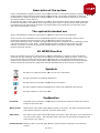
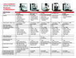
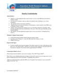
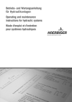
User Manual
EasyLine system
Version 01.11
Airtec® A/S • Hvedemarken 21 • DK-7620
7620 Lemvig • Phone: +45 99631300 • www.airtecsolutions.com
Contents
•
•
•
•
•
•
•
•
•
•
•
•
•
•
•
•
•
•
•
•
•
•
•
•
•
•
•
•
•
•
•
•
•
•
•
•
•
•
•
•
•
•
•
•
EU-Declaration....................................................................
Declaration....................................................................
2
The right choice..................................................................
3
Delivery.............................................................................
3
Description of the system.....................................................
4
The system's intended use ..................................................
4
EU WEEE directive...............................................................
...............................................................
4
Symbols and Explanations....................................................
4
Conditions for installation.....................................................
5
Water supply requirements...................................................
6
Water quality and Power supply requirements.......................
7
Installation of the EasyLine system......................................
8
Installation of SlipLock.........................................................
.........................................................
9
Installation of Low Flow kit...................................................
10
Start up the EasyLine system with DigiSens sensor.................
11
Start up the EasyLine system with HMH sensor.......................
12
By-pass/overpressure
pass/overpressure adjustment.........................................
13
Reset Thermal switch...........................................................
13
Hygienic Rinse system.........................................................
13
Set the by-pass...................................................................
pass...................................................................
14
Reading Timer for running hours...........................................
15
Reading Timer for working pressure......................................
16
Flow control adjustment.......................................................
17
Programming DigiSens.........................................................
.........................................................
18
Maintenance/Service, EasyLine system..................................
19
Maintenance/Service, Atomisers............................................
20
Service checklist.................................................................
21
Flow diagram – out house....................................................
22
Disinfection of the system....................................................
23
Installation, System overview...............................................
24
Troubleshooting..................................................................
25
Spare parts.........................................................................
26
Spare parts recommended...................................................
27
Datasheet EasyLine.............................................................
.............................................................
28
Datasheet HydroJet atomiser................................................
31
Datasheet HydroTrio atomiser...............................................
32
Datasheet HydroOne atomiser...............................................
33
Datasheet SlipLock with nozzle.............................................
34
Datasheet for Watts consumption – Electric Motor…………………..
35
Datasheet high-pressure hose...............................................
36
Datasheet DigiSens 1000 sensor..........................................
37
Datasheet HMH Sensor........................................................
38
Certification........................................................................
39
General Conditions..............................................................
..............................................................
40
Log Book............................................................................
41
Electrical diagram enclosed
Translation of the original User Manual
EU-Declaration
Declaration
EU-agreement-declaration
declaration
Factory:
Airtec® A/S
Hvedemarken 21
7620 Lemvig
Denmark
Phone: +45 99631300
Fax:
+45 97811101
E-mail: [email protected]
Web: www.airtecsolutions.com
Declares hereby, that:
Machine:
Pressure humidification system
High-Pressure
Mark:
Airtec®
Type:
EasyLine
Machine no.:
946
Is fabricated in conformity to the technical directive 98/37/EF-2006/42/EF,
98/37/EF
2004/108/EF,
2006/95/EF under special reference to the health and safety demands in connection with the
construction and manufacturing of machines.
Title:
Managing Director
Name:
Bo Rahbek
Company:
Airtec® A/S
Lemvig the
2/2 - 2012
Managing Director
Page 2 of 41
The right choice
Congratulations on choosing an Airtec® high-pressure
pressure humidification system. By purchasing an
Airtec® EasyLine System, we guarantee that the product is produced according to the Quality–
Quality
Environment and Hygiene certificates, ISO 9001, ISO 14001 and ISO 22000 HACCP.
This manual is written to ensure the correct use, performance and long life of the system and is
prepared for the use of engineers and properly trained technical personnel.
Read this manual carefully before installation and before using your Airtec® humidification system.
Airtec® reserves the right to update their systems without giving prior notification.
Correct Mounting and Maintenance is Important
Follow the Airtec® Guidelines as written in this manual, and your humidification system will work to
your satisfaction.
Before any work on the system starts, the system must be disconnected from the power supply and
secured against re-connecting.
Installation, maintenance, repair and dismantling should only be carried out by qualified technical
personnel.
In order to ensure against stagnant water and the risk of bacteria the humidifier must be left switched
on continuously. If the system is shut down for any extended period of time, then the system must be
disinfected, as described in the procedure within this manual.
Should there be any problems, or any doubt about the installation or operation of the humidification
system, please do not hesitate to contact us for help and guidance. With maintenance on a regular
basis and by following the guidelines, you can be confident of a perfect working system for years to
come.
To guarantee that the system always works correctly we recommend you take out a service contract
with using Airtec® authorised personnel. Our fully qualified personnel will then take care of the
maintenance and servicing of the system at the correct intervals.
Delivery
When unloading and handling the products, make sure you use lifting equipment and methods, that
will not cause damage to the products.
When you receive the goods please make sure that they are as agreed, and that there is no damage,
transportation damage)or anything missing from the shipment.
Normally the goods will arrive wrapped and packed in protective materials. Please do not remove this
protective material before installation.
Should there be any cause to complain, you must inform Airtec® immediately.
We refer to the general conditions for Airtec® A/S which you will find on the Order Confirmation.
Transportation.
During transportation the EasyLine must be kept upright. This is to avoid oil leaking from the pump.
Page 3 of 41
Description of the system
Airtec® humidification systems consists of the required number of atomisers/nozzles for appropriate
output together with a control unit and a high-pressure
pressure pump. The system is designed for direct air
humidification in industrial applications being installed by authorised technical personnel. All systems
are tested at Airtec® before delivery.
All systems use water under high-pressure
pressure to produce finely atomised sprays which rapidly evaporate
to raise the humidity to the desired level. Pressure and flow control is via the control panel which also
incorporates the fail safe devices Operation is fully automatic and regulated by the humidity sensor
with optional temperature sensor.
The system's intended use
Airtec® humidification systems are intended for adiabatic cooling and air humidification.
Airtec® develop and manufacture air humidification systems to improve the total outcome of the
productions facilities and gives people a more comfortable working environment.
Electrostatic discharge, dust, moisture shrinkage and temperature variables are the challenges to find
customised solutions to solve. Airtec®’s application experience includes wood, textile and paper
industry, producers of electronic equipment, tobacco, plastic, automotive, aerospace, malting,
hatchery and food industry.
EU WEEE Directive
Buyers of systems from Airtec® take over the producers obligations in relation to the EnvironmentEnvironment
protection law § 9 regarding waste electrical and electronic equipment (WEEE) directive. Airtec® refer
to the current law by referring the Environment-protection
protection law: ”Environment-protection law § 9 j.
Producers and importers must be responsible for the disposal and management of all waste including
waste of electrical and electronic equipment which is manufactured by the producer or importer”.
Symbols
This sign is for electrical waste, and is put on the components.
This sign represents a mandatory instruction.
This sign refers to important supplementary information.
This sign indicates specific detailed actions required at installation and start-up.
start
This sign indicates an incorrect action.
Explanation
Permeate:
Permeate is the processed, unsalted water which the RO system produces and carries
further to the water tank.
Waste water:
Waste water is the water which will be carried to the drain. This water contains the salts
and minerals which are removed from the mains water.
Raw water:
Raw water is the water required to supply the system, often delivered from waterworks or
a private mains supply. The raw water must meet all local and national regulations and
requirements. See page 7.
Softened water: Softened water is the raw water which is produced after treatment in the softening
system.
Psge 4 of 41
Conditions for Installation
Installation place
EasyLine must only be installed in a room where there is a drain.
EasyLine measurements: H: 1020 mm - B: 530 mm - D: 360 mm.
Weight: 50 kg.
EasyLine must be installed in a non-freezing
freezing room with surrounding room temperature at
max. + 35ºC.
Overview of typical system
Black
= Water supply
Red
= Connection to drain
Purple = Softened water
Green
= RO water
Blue
= Water under 50-55
55 bar pressure to the atomiser
Yellow = Cable
Zone 1
Zone 2
A drain in the floor must be available around EasyLine.
Non-freezing installation room.
Surrounding room temperature for EasyLine at max. + 35ºC.
Page 5 of 41
Supply requirements
Water connection
Water supply to the EasyLine system must be constructed according to local regulations.
The system must only be connected to the cold mains water supply(max. + 15ºC) without
the prior risk for growing up conditions for bacteria.
The water pressure must be delivered to the EasyLine pump at a minimum of 2 bar
pressure and a maximum of 4 bar pressure when the Airtec® EasyLine system is
running at maximum output.
If a water softening system is installed to the system the delivered water pressure to the
water softening system must be at minimum of 3 bar and maximum of 7 bar, yet must
the water pressure to the EasyLine pump not exceed 2 – 4 bar as previously stated.
When connecting a reverse osmosis system; please see separate User Manual.
Drain for the pressure-release
release venting has to be 40 mm in diameter and terminated 20
cm above floor drain.
The water supply must be protected against pollution by 2 off connected 1µm filter which
are included within the delivery.
High-pressure
connection
Water inlet pressure
which can be seen in the
display at the frequency
inverter
Water outlet, drain for
pressure-release
Water inlet
The water pressure must, when the system is running at maximum output, give a
pressure at min. pressure of 2 bar up to max. of 4 bar and must be terminated in a Ball
valve with a 3/4” external thread.
Ensure that the water pressure is kept constantly at min. pressure of 2 bar up to max. of
4 bar when the Airtec® EasyLine system is running at max. output.
Drain for the pressure-release
release venting has to be 40 mm in diameter and terminated 20
cm above floor drain.
The water supply must be protected against pollution by 2 off connected 1µm filter which
are included within the delivery.
Page 6 of 41
Supply requirements
Water quality
Water quality must comply with the existing order of drinking water, but at least equivalent to
a Danish drinking water standard.
Max. water temperature + 15 ºC.
Airtec® recommend Reverse Osmosis water (RO water) for the best results.
If the hardness of the water is more than 3º dH, Airtec® recommends the installation of a
Softening System.
If no water treatment is installed, Airtec® recommends that water hardness is no higher than
3ºdh.
If there is any doubt or uncertainty about the content or the quality of the mains water or the
drinking water, we recommend a water analyse is carried out.
Power supply
All installations/connections must be carried out according to the existing law and regulations.
Airtec® is following the existing laws and regulations for installation/connection according to
the EU regulations.
Before any work on the system starts, the system must be disconnected from the power
supply and secured against re-connecting.
connecting.
Note: the Airtec® system include a frequency inverter. (For further details see separate
manual).
EasyLine system
Power supply:
230V+PE
Fuse:
13 A
The electric installation has to be 230V+PE (13A) and is terminated close to the EasyLine in
an approved supply separator.
Check that the power supply has correct voltage 230V+PE.
The installation is protected by a 13 A fuse.
Page 7 of 41
Installation of the EasyLine system
Hose, Nozzle and Fitting
Handle hoses and other parts of the system in a way that prevents dust and other
partials entering the system, otherwise it will cause problems to the spraying efficiency.
Hose ends must be sealed during installation and leading..
It is very important to use the right tools, -especially for cutting hoses. When cutting
hoses it is important to create “straight, clean” ends, before connectors are fitted.
Wrong tools for cutting
hoses
The Nozzles are to be tightened by hand only and must be tightened until the two
metal surfaces meet each other. Do not use tools.
Do not use tools
Installation of hose in SlipLock fitting.
The high-pressure
pressure hose must be cut with a sharp tool/scissor to produce “straight,
clean” ends.
Push the hose into the SlipLock fitting, give a small pull backwards and to ensure the
hose is locked in.
Page 8 of 41
Installation of SlipLock
The unique SlipLock system is specially designed by Airtec® for supplying water under high pressure.
The system contains of SlipLock fittings and polyamide hoses that with simple means, is fitted without
special tools or extensive experience.
The SlipLock system is supplied as an assembly kit. All components have
o-ring
ring seals, this eliminates the need for special tools and guarantees it
seals every time.
With a simple blind cork the system can be assembled as an elbow and
used for the installation of the hoses as well.
The kit is assembled and tightened with a wrench.
- And is now ready for use.
The high pressure hose is cut with a sharp scissor.
- And the SlipLock fitting is clicked on.
The Sliplock is now ready for use.
• Fittings are produced in brass, sealed with a nickel plated surface to ensure optimised corrosion resistance.
• The hoses is produced in Polyamide 12 ( PA 12-HL)
HL) Black in colour, stabilised against heat ageing, as well
as being light stabilised.
Page 9 of 41
Installation of Low Flow kit for high-pressure
high
Pump
Type A-600
600 – A-700
Low Flow kit consist of:
Hose.
Special adapter without nozzle.
Special adapter with nozzle - internal.
Terminate power and water supply.
Remove both blind cork’s, one at the low-pressure
low
(water inlet) and
one at the high-pressure
high
(water outlet) in the cylinder head.
Installation of the Low Flow kit:
The special adapter without the nozzle to be installed in the threadthread
hole at the high-pressure
high
side (at the top). The special adapter with
nozzle (internal) to be installed in the thread-hole
thread
at the low-pressure
side (bottom).
Connect the 2 special adapters with the enclosed/delivered hose.
Note; At service the function of the Low Flow kit must be checked.
Eventually replacing the special 21 l/h nozzle.
Page 10 of 41
Running the EasyLine system with DigiSens sensor
The following text explains the ”start up” procedure, and the basic adjustments of the system.
Before the system starts running, please check all connections again, to ensure that the installation
instructions have been followed.
Transportation
During transportation the EasyLine must be kept upright. This to avoid oil leaking from the pump.
Check the nozzles
Check that nozzles are fitted in all nozzle holders/atomisers, and that these are tightened by hand.
Start up EasyLine
Connect power –and water supply.
Set all sensors to 0% RH. (See page 18).
Activate fuse F1 for control circuit. (See inside EasyLine).
Set the sensor for zone (room) 1 to 100 % RH and Temp. at 0 ºC.
Working pressure of 50-55
55 bar will be reached in 30–60
30
seconds. (See display at frequency
inverter). If the working pressure is not 50 – 55 bar the bypass must be adjusted. (See page 13).
Working pressure 50-55 bar will
be reached in 30–60 seconds,
see display at frequency inverter.
(See page 16)
Off/On
Red ”Alarm Reset”
button
Check the system for leaks.
Set the sensor to 0% RH.
Repeat the steps above for all zones (rooms).
When all zones are tested, insert the set point in the sensor on the required RH and Temp. value.
The system is now running.
Frequency inverter
Fuses for control
circuit
After installation, service or repair of the humidification system unusual running conditions may be
observed due to air in the system, this can show as small drips from the nozzles when you start and
stop the system. Under normal conditions this will end within 2 - 4 days of running.
Your Airtec® humidification system must always be connected to the power supply and running. This
because of considerations. If there are any periods where you do not require humidification, the
system must not be shut down, instead you must set the system to 0 % RH.
Page 11 of 41
Running the EasyLine system with HMH sensor
The following text explains the ”start up” procedure, and the basic adjustments of the system.
Before the system starts running, please check all connections again, so that the installation
instructions are followed.
Transportation
During transportation the EasyLine must be kept upright. This to avoid oil leaking from the pump.
Check the nozzles
Check that nozzles are fitted in all nozzle holders/atomisers, and that these are tightened by hand.
Start up EasyLine
In the following use the controls on the front of the EasyLine and the HMH sensor.
Connect power –and water supply.
Adjustment of
the HMH
sensor
Set all sensors to 0% RH.
HMH sensor
Activate fuse F1 for control circuit. (See inside the EasyLine).
Turn the Off/On button on the front of the EasyLine to ”On” position.
Set the sensor for zone (room) 1 to 100% RH.
Press and hold the red ”Alarm Reset” for minimum 5 seconds. (System starts).
Working pressure of 50-55
55 bar will be reached in 30–60
30
seconds. (See display at frequency inverter).
If the working pressure is not 50 – 55 bar the bypass must be adjusted. (See page 13).
Check the ventilator in the atomisers, and see that these are running properly.
If start/stop of ventilator is installed, zone need to be working in order to check function of ventilator.
Check the system for leaks.
Set the sensor to 0% RH.
Repeat the steps above for all zones (rooms).
When all zones are tested, adjust the setpoint on the required RH value. The system is now running.
Red ”Alarm Reset”
button
Off/On
Freqency
inverter
Fuses for
control circuit
Calibration of HMH sensor
HMH sensors must be calibrated once a year to get optimal accuracy. Special approved reference tool
must be used. Contact Airtec®.
After installation, service or repair of the humidification system unusual running conditions may be
observed due to air in the system, this can show as small drips from the nozzles when you start and
stop the system. Under normal conditions this will end within 2 - 4 days of running.
Your Airtec® humidification system must always be connected to the power supply and running. This
because of considerations. If there are any periods where you do not require humidification, the
system must not be shut down, instead you must set the system to 0 % RH.
Page 12 of 41
By-pass/overpressure
pass/overpressure adjustment
To secure the system against overpressure when running, by-pass
by
is adjusted to open at 65 bar.
This will avoid short overpressure at the system. Follow the instructions below.
Adjust bypass valve so that ”working pressure” is max. 40 bar. Read timer at the frequency
inverter.
The pump will now run at full speed.
Set the set point at pressure to 70 bar at frequency inverter. (See instruction page 14).
Adjust bypass valve so that ”working pressure” is 65 bar.
Set the set point at pressure to 50 bar at frequency inverter (See instruction page 14).
Working pressure will now drop to approx. 50 - 55 bar.
Lock the by-pass at the closure nut.
Frequency inverter
is inside the EasyLine
Adjust by-pass
Closure nut
Reset Thermal switch
Thermal switch at
the pump. For reset
remove the
protective hood.
Press the red
button to reset
Hygiejnic Rinse system
Hygienic Rinse system is activated at delivery and the system will run for 20 sec. every 6 hours,
and thereby the water in the system will be exchanged.
The Hygienic Rinse can be adjusted to suit the specific customer requirements, contact Airtec® A/S.
Page 13 of 41
Adjustment of By-pass
By
By-pass
pass is adjusted at the frequency inverter.
Press ”ESC” 4 times – until it says ”PX.XX” in the display, press ”Enter”.
PX.XX
It says ”50.00” in the display, with arrow up, arrow down and arrow to the right adjust the value to
”70.00”, press ”Enter”. Read the working pressure (see page 16). Adjust by-pass
by
to 65 bar (see page
13), the inverter will now run full speed.
70.00
Adjust value to ”50.00”, press ”Enter”. The inverter will regulate.
50.00
Press ”ESC” 4 times until it says ”PX.XX” in the display, to return to front page.
PX.XX
Page 14 of 41
Reading Timer for running hours
Read timer for running hours at the frequency inverter.
Press arrow down until is says ”MON” in display, press ”Enter”.
MON
Press the arrow until is says ”U4-01”
01” in the display, press ”Enter” 2 times, read the hours.
U4-01
Press ”ESC” 4 times until it says ”PX.XX” in the display, to return to front page .
PX.XX
Page 15 of 41
Reading Timer for Working pressure
Reading Timer for working pressure at the frequency inverter. The system shall be operating.
Press ”ESC” 4 times
Press arrow down until it says ”MON” in the display, press ”Enter”.
MON
Press the arrow until is says ”U1-13”
13” in the display, press ”Enter” 2 times, read the working pressure.
U1-13
Press ”ESC” 4 times until it says ”PX.XX” in the display, to return to front page.
PX.XX
Page 16 of 41
Flowcontrol adjustment
Adjust Flowcontrol at the frequency inverter. All zones shall be running.
Press ”ESC” 4 times . Read the value.
Press arrow down until it says ”PAR” in the display, press ”Enter”.
PAR
Press the arrow until it says ”Q1-01”
01” in the display, press ”Enter” 2 times, adjust the value
approx. 5 over reading value, (see the top of this page), press ”Enter”.
Q1-01
01
Press ”ESC” 4 times until it says ”PX.XX” in the display, to return to front page.
PX.XX
Page 17 of 41
Programming DigiSens 1000 Sensor
Normal Process data display
Display when ON/OFF pressed
toggles between Normal and this
Data from
integrated
humidity and
temp. sensor
Data from integrated
Real Time Clock and
external temp. sensor
Communication Failure
Alarm indicator
Alarm signalling
Low hum. or dew High hum or dew
Serious error on
communication between
Paned and Main Controller
Press SET to reset
or come again on
repeated time
intervals as set
Check wires!
Hold SET key for 5 seconds to get to all settings
1 Change values with arrows up and down keys.
2 Proceed to next level with SET key.
3 Will circle all menus when SET is pressed.
4 Menus displayed depends on DIP switch setting in panel, RH or DEW.
5 ON/OFF key will toggle between normal process display and special display, at any time.
6 If in settings, ON/OFF key will always return to normal process display.
Humidity Settings
General Advanced Settings
Hold SET key for 10 seconds
Temp. Settings
Deactivate Sensor
Hold ON/OFF key for 3 seconds.
Sensor is now deactivated.
Hum Set
32,0 % RH
01 PUSH SET
Hum Set
32,0 % RH
01 PUSH SET
Soaking
time
05 ON/OFF
Temp Alarm L
-20,0 ºC
11 PUSH SET
Set Year
2011
17 PUSH SET
Activate Sensor
ON Time
OFF
03 PUSH SET
Temp Set
32,0 ºC
02 PUSH SET
OFF Time
OFF
04 PUSH SET
ON Time
OFF
03 PUSH SET
Hum Hys
03,0 %RH
06 PUSH SET
Alarm Repeat
1 Min
12 PUSH SET
FACTORY SET
NO
18 PUSH SET
Hold ON/OFF key for 3 seconds.
Sensor is now activated.
Soaking Function
Temp Hys
2,0 ºC
07 PUSH SET
Set Clock
21:16
13 PUSH SET
Hold Arrow up key for 3 seconds.
Display shows “Soaking ON”.
Deactivate by holding Arrow
down key for 3 seconds.
Display shows “Soaking OFF”.
OFF Time
OFF
04 PUSH SET
Hum Alarm H
80,0 %RH
08 PUSH SET
Set Date
27
14 PUSH SET
Hum Alarm L
10,0 %RH
09 PUSH SET
Set Month
November
15 PUSH SET
Temp Alarm H
40,0 ºC
10 PUSH SET
Set Week day
Monday
16 PUSH SET
Page 18 of 41
Maintenance/Service, EasyLine
Airtec® EasyLine is made of components that in general require very little maintenance.
The following texture will explain the required maintenance, of the EasyLine system, to
maintain long term reliability of the system.
At any defect in the system; look at the Troubleshooting schedule page 25 or contact Airtec®.
Weekly
EasyLine:
Check that the ventilator in the EasyLine is running and that the filters for this ventilator are clean.
Pump:
Check that, water supply pressure is min 2 bar up to max. 4 bar when system is running.
Check that the working pressure is 50-55
55 bar. (See display at frequency inverter)
If the working pressure is not 50 – 55 bar the bypass must be adjusted. (See page 13).
Check the oil level on pump, the oil level must max. reach the maximum mark at the oil stick.
If oil is filled below this level it can cause waste of oil.
Check that, colour of oil is light brown, and no foam is created (stop pump for 1 minute before
checking. To stop pump set each zone, one of the time, at 0% RH).
Check for oil or water leaks. Be aware that the connection between motor and pump has from factory
been oiled and that can cause small droplets of oil below the pump. There can also obtain small
water droplets below the pump because of condensation. Clean below the pump when needed.
Monthly
Switch off water supply. System must go into alarm within 60 seconds, and alarm light is flashing.
This function will protect the pump e.g. in case of leak of water and or no water-pressure.
water
Half-yearly/Yearly
Depending on the supplied water quality and the amount of use of the system, the service interval for
a professional service will vary. To obtain the optimal function of the system, Airtec® recommend
that at normal operation a professional service is done twice a year.
Check the hygrostats with a calibrated humidity sensor. Contact Airtec®.
Oil in the pump must be changed min. once a year or every 2000 hours.
The oil level must max. reach the maximum mark at the oil stick.
Oil type: GEARTEX EP-C SAE 80 W-90.
Generally
Water filter from water supply must be changed when needed, depending on water quality.
Oil change at the pump: First oil change is due after 300 hours, then for every 2000 hours yet min.
once per year. If there appear condensed water in the oil it must be changed. The oil must be refilled
to the maximum mark at the oil stick. Oil type: GEARTEX EP-C
EP
SAE 80 W-90.
Seals in the water part of the pump must be changed when needed.
Here you fill up the oil
Drawing off oil; drain
plug for draining of
pump, the drain plug is
underneath the pump
Water Softening system (if installed):
At weekly intervals a test must be taken of the water to check if the system still delivers softened
water, use the Airtec® test-kit delivered. Use the test-valve at the water softening system. If the
system is used as preparation to a Reverse Osmosis system, it's recommended to make a daily
check. (See separate User Manual).
Reverse Osmosis system (if installed):
Check the RO water conductivity/dry solid with supplied measurement device. Water conductivity will
vary depending of raw water quality but Airtec® recommend it to be between 10 – 30 µS/cm. If it is
under 10 µS/cm it may cause problem for humidification functionality, if it is more than 30µS/cm it
can be a sign that the membrane is defect, contact Airtec®. (See separate User Manual).
Measuring instruments and measuring points must be cleaned with alcohol before testing. When
testing avoid any skin contact with the water. If any deviations Airtec® must be informed.
Page 19 of 41
Maintenance/Service
Maintenance/Service, Atomisers
At any defect in the system; look at the Troubleshooting schedule page 25 or contact Airtec®.
Weekly
Check that, ventilator is running, and that it’s clean and quiet.
Check that the nozzles are atomising correct, as in a cone shape.
Monthly
Clean the atomisers; ventilator and grills.
Page 20 of 41
* At the Service tighten all connections in the controller.
At subsequent Services tighten only main electricity.
** The drain hose should not be below the water line in the
drain and must remain above it at all times.
*** The oil has to be changed at every 2000 hours.
But the first time at 300 hours. The Oil has to be
changed min. once a year. If condensed water appear
in the oil, the oil has to be changed.
**** The seal in the pump must be changed if needed.
Page 21 of 41
Flowdiagram out house –
Concerning ISO 22000 HACCP running of
Airtec® humidification system
• Log book where all tests, analysis and changes concerning the system are registered.
• In general the customer should follow the supplied user manual.
• Weekly conductivity test at the RO tank.
o
Sample is taken at designated place.
o
Normal conductivity range 10-30
30 µS/cm, although max. 50.
• Water analysis.
o
Water analysis by start up of system.
o
Water analysis every 6 months.
o
Water sample is taken at the nozzle furthest away in each zone .
o
Bacteria count (Cfu) accordingly to the drinking water standard 200 Cfu/ml.
o
Bacteria count (Cfu) for atomised water for humidification purpose accordingly to VDI
6022 max 1000 Cfu/ml.
If the system fails a test another test is done to check.
o
o
Hereafter authorised Airtec® personnel should be contacted to find the reason and to
disinfect the system.
When the system has been opened a water test should be performed.
o
• UV light.
o
Check functionally weekly.
o
Change the light bulb every 12 months or when needed.
• Condensation of water or water on the floor should taken care of momentarily.
• To obtain the optimal function of the system Airtec® recommend that at normal operation a
professional service is done twice a year.
• When the system comes to a stand still of a longer lasting period the system should be serviced by
authorised Airtec® personnel to disinfect and make the system ready for start up.
• The system should be audited by the customer continuously.
• Deviations from the above mentioned should be reported to Airtec® for review.
• The system should not be serviced/opened without authorised supervision.
• Critical control points.
o
Installation.
o
Running the system.
o
Training.
o
Regular service check of the equipment.
o
Regular water analysis.
o
Regular monitoring of operation.
o
Service interval.
o
Use of User Manual.
o
Inappropriate operation.
o
Current audit and own control.
o
Disinfection procedure.
o
Traceability.
o
Authorised handling.
o
Logbook.
ISO 22000 HACCP system should contain the following:
• Water supply should live up to drinking water standards, but at least equivalent to a Danish drinking
water standard.
• Reverse Osmosis water treatment.
• Frequency inverted pump system.
• Hygienic rinse system.
• Hoses sized in a way where you have the least standing water possible.
• System build in a hygienic design using material that ensures minimum level of bacteria growth.
• Service of the system twice a year by authorised Airtec® personnel.
• If customer wish, UV lighting of the water.
Page 22 of 41
Disinfection of Airtec®
humidification system
In order to establish the system's bacteriological condition, should a water test be taken. The water
sample must be taken at the atomiser/nozzle which is furthest away form the pump station. Measuring
instruments and measuring points must be cleaned with alcohol before testing. When testing avoid any
skin contact with the water. The water sample must be send to a internationally recognized laboratory
to get the analyses wanted.
If 2 consecutive tests show, that the water excess the authorized limit of Cfu figures the system must
be disinfected in accordance with Airtec® procedure as described below.
Procedure for disinfection:
Plan the progress in this task.
Read and understand this procedure for disinfection and the supplier user manual.
Measure the waters pH value of the atomiser/nozzle furthest away from the pump station. The
sample is taken by collecting atomised water from a nozzle. Note the test to be able to compare.
The same point is then later to be used to take out future water samples.
The water inlet to the parts which is wanted disinfected is to be connected to a mixer tank or
dosage equipment which will supply the system with 1 to max. 2% disinfection fluid. Afterwards
measure the pH value of the fluid and note the value to be able to compare.
Where pump station and atomisers/nozzle will be a part of the disinfection, the part of the water
which consist of disinfection fluid must be connected to drain, when there are no people in the
room. The rooms must be ventilated wither mechanical or by creating a ventilation by opening
doors/windows.
Alternative must all atomisers/nozzles in each zone be bleed with hoses directly at the nozzle and
collected in containers. The collected water can be led to drain.
Switch on the humidification system, and in the zone (zones) which are activated measure the pH
value of the water to ensure that the disinfection fluid is completely distributed to the whole system.
Meaning that the pH value is the same as measured at mixing the fluid. Afterwards switch off the
humidification system.
The fluid is to be contained in the system for 30 min. to max. 1 hour, after which the system must
be rinsed with clean water. Then measure the pH value to ensure that the value is the same as
before the disinfection started.
Then it is ensured that the system is empty for disinfection fluid.
The disinfection fluid used is approved by the Danish Ministry of Veterinary & Food.
Information and supplier user manual can be supplied by contacting Airtec® A/S.
Page 23 of 41
Installation
System Overview
Softener
Control
Unit/Pump
230V + PE – 13A
RO System
Hydrophor
pump
Sensor
Permeate
Tank
1
2
3
Sensor
Atomiser
Drain
Sensor
Atomiser
Atomiser
Page 24 of 41
Troubleshooting
Error/Error message:
Cause:
Solution:
Pump does not start.
Relay is switch off.
Check fuses and power supply.
Motor or pump are blocked.
External stop is activated.
Check the external unit.
No zones need humidity.
No light in On/off button.
No power supply.
Check fuses and power supply.
Light bulb is defect.
Replace light bulb.
System is off.
Pump is running but is not
bringing water into the
zones (rooms).
Defect Solenoid valve.
Replace Solenoid valve.
Nozzle is dripping when
system is running.
Nozzle is blocked.
Replace nozzle.
Alarm light is on.
(After repairing or reset of
errors, always press the
Alarm Reset button).
Missing water pressure.
Water pressure is too low.
Check the water supply.
Filter is blocked.
Check the water filter.
Error on Frequency inverter.
Motor or pump are blocked.
Call Airtec®.
Pressure is too high.
Normally (50-55
55 bar).
Adjust Bypass to 50-55 bar.
Call Airtec® personnel.
Temp. on pump is too high.
Reset the Thermal switch at the
pump. See picture at page 13.
Filter in ventilator at EasyLine is
blocked.
Replace filter in Ventilator.
Defect Solenoid valve.
Replace Solenoid valve.
Defect pump.
Replace pump.
Water leak.
System does not run.
Break on hose.
Replace hose.
Or other leak.
Call Airtec® personnel.
Power cut.
Press the Reset/Start button.
Page 25 of 41
Spare parts
Description
Part no.
Frequency inverter
231230
Sensor DigiSens 1000
121200
Sensor HMH
121300
Control Unit ventilator
221310
Filter for Control Unit ventilator
231250
Pressure button, red
231820
LED element, red
231830
Turning button
231825
LED element, green
231835
Contact bloc NO
231840
Automatic fuses 2A 1 Pol
231310
Automatic fuses 13A 1 Pol
231320
El-Motor
231740
Non-return valve, 1/8”
161710
Pressure transmitter 0-100 bar
231122
Control relay 24 V AC
231140
Thermal switch
231210
By-pass
201410
Pump A-600
201310
Solenoid valve, complete
211110
Water filter 10”, 60%
191010
Ventilator for HydroJet atomiser
221120
Ventilator for HydroTrio atomiser
221210
Ventilator for HydroOne atomiser
221310
Nozzle, complete 5,3 l/h, no. KBN
182340
Nozzle stainless steel, complete 4 l/h, no. 2
182320
Nozzle stainless steel, complete 2,7 l/h, no. 1
182310
Sealing kit for Pump A-600
201430
Low Flow Kit kontin. 21 l/h
111315
Salt for softening system, 25 kg. per back
176225
Page 26 of 41
Spare parts Recommended
Description
Part no.
Solenoid valve, complete
211110
Water filter 10”, 60%
191010
Oil for Pump A-600
201450
Nozzle, complete 5,3 l/h, no. KBN
182340
Nozzle stainless steel, complete 4 l/h, no. 2
182320
Nozzle stainless steel, complete 2,7 l/h, no. 1
182310
Sealing kit for Pump A-600
201430
Salt for softening system, 25 kg. per back
176225
Page 27 of 41
Datasheet EasyLine
Page 28 of 41
Datasheet EasyLine incl. DigiSens sensor
This datasheet contains the overview for EasyLine and shows the opportunity for facilities.
EasyLine standard incl. DigiSens sensor
3
Humidity Control (number of zones)
3
Temperature Control (number of zones)
Yes
Temperature Control, pump
Variable On/Off time
Yes
Hygienic Rinse-system,
system, replacement of water
Yes
Timer for running hours
Yes
Potential free inlet
Yes
Alarm indicator at the control unit
Yes
Flow guard
Yes
Water pressure alarm
Yes
Yes
High/Low humidity alarm
Option
Ventilator start/stop
h1020, w530, d360 mm
Measures
50 kg
Weight
Surrounding temp.
1 – 35 ºC
Frequency inverter
1,1 kW
El-motor
1,10kW/1000 rpm
Supply
230 V +PE – 13 A
< 70 dB(A)
Capacity
12 – 600 l/h
1020 mm
Noise level
Page 29 of 41
Datasheet EasyLine incl. HMH sensor
This datasheet contains the overview for EasyLine and shows the opportunity for facilities.
EasyLine standard incl.. HMH sensor
3
Humidity Control (number of zones)
Temperature Control (number of zones)
No
Temperature Control, pump
Yes
Variable On/Off time
No
Hygienic Rinse-system,
system, replacement of water
Yes
Timer for running hours
Yes
Potential free inlet
Yes
Alarm indicator at the control unit
Yes
Flow guard
Yes
Water pressure alarm
Yes
No
High/Low humidity alarm
Option
Ventilator start/stop
h1020, w530, d360 mm
Measures
50 kg
Weight
Surrounding temp.
1 – 35 ºC
Frequency inverter
1,1 kW
El-motor
1,10kW/1000 rpm
Supply
230 V +PE – 13 A
< 70 dB(A)
Capacity
12 – 600 l/h
1020 mm
Noise level
Page 30 of 41
Datasheet HydroJet atomiser
HydroJet atomiser
Axial ventilator
Ventilator type
24 l/h. (6x2,7/4,0/5,3 l/h)
Capacity
Working pressure
50-55
55 bar
Supply
230 V AC
1850 m³/h
Blower capacity
Rpm
940 rpm
Max. input
80 Watt
0,39 A
Max. current
Rooms with min. 4 m. ceiling
Usage
40°C,
C, 60% RH
Surroundings
< 70 dB(A)
Noise level
Diam. 430, H 490 mm
Measures
Weight
7 kg
Nozzles per atomiser
6 off
Min. distance 0,5 m.
Min. distance 3 m.
Min. distance 3 m.
Min. afstand 4 m.
490 mm
HydroJet
Ø 430 mm
Page 31 of 41
Datasheet HydroTrio atomiser
HydroTrio atomiser
Centrifugal ventilator
Ventilator type
12 l/h (3x2,7/4,0/5,3 l/h)
Capacity
Working pressure
50-55 bar
Supply
230 V AC
Blower capacity
645 m³/h
Rpm
1000 rpm
65 Watt
Max. input
0,29 A
Max. current
Rooms with low ceiling and/or
limited space
40°C, 60% RH
Usage
Surroundings
< 70 dB(A)
Noise level
H: 300, W: 500, D: 240 mm
Measures
Weight
5 kg
Nozzles per atomiser
3 off
Min. distance 0,5 m.
Min. distance 5 m.
Min. distance 3 m.
300 mm
HydroTrio
500 mm
Page 32 of 41
Datasheet HydroOne atomiser
HydroOne atomiser
Axial ventilator
Ventilator type
4 l/h (2,7/4,0/5,3 l/h)
Capacity
50-55
55 bar
Working pressure
Supply
230 V AC
Blower capacity
164 m³/h
Rpm
2850 rpm
22 Watt
Max. input
0,14 A
Max. current
Rooms with low ceiling and/or
limited space
40°C,
C, 60% RH
Usage
Surroundings
40,5 dB(A)
Noise level
H: 125, W: 125, L: 150 mm
Measures
Weight
2 kg
Nozzles per atomiser
1 off
Min. distance 0 m.
Min. distance 3 m.
Min. distance 2,5 m.
125 mm
125 mm
HydroOne
Page 33 of 41
Datasheet SlipLock with nozzle
The unique SlipLock system is specially designed by Airtec® for supplying water under high pressure.
The system contains of SlipLock fittings and polyamide hoses that with simple means, is fitted without
special tools or extensive experience.
The SlipLock system is supplied as an assembly kit. All components have
o-ring
ring seals, this eliminates the need for special tools and guarantees it
seals every time.
The kit is supplied with a special nozzle that ensure a very good atomisation
at 50 bars pressure. The nozzle is shielded with ceramics inside ensuring a
prolonged lifetime compared with traditional nozzles.
With a simple blind cork the system can be assembled as an elbow and
used for the installation of the hoses as well.
The kit is assembled and tightened with a wrench.
- And is now ready for use.
The high pressure hose is cut with a sharp scissor.
- And the SlipLock fitting is clicked on.
The nozzle is now installed and ready for use.
Please notice that the nozzle can be adjusted and is able to rotate 360
degrees - even after being installed.
The nozzle should be installed where there is some circulation of air to
ensure the best evaporation possible.
• Fittings are produced in brass, sealed with a nickel plated surface to ensure optimised corrosion resistance.
• The hoses is produced in Polyamide 12 ( PA 12-HL)
HL) Black in colour, stabilised heat ageing as well as
being light stabilised.
Page 34 of 41
Datasheet for Watts consumption – Electric Motor
Measurement of watt consumption of 1.1 kW electric motor
Flow
Watt
100
407
200
622
300
871
400
1140
500
1250
600
1375
Flow Diagram for Watts consumption by 1.1 kW electric motor
2000
1800
1600
Watt
1400
1200
1000
800
600
400
200
100
200
300
400
Flow
Page 35 of 41
500
600
700
800
Datasheet high-pressure
high
hose
Dimensions and Pressures
Part
number
Tube OD
+ wall
thickness
(mm)
NR4X1/5
NR10X2/5
Max.
working
pressure at
+23 ºC
(Bar/psi)
Min.
bend
radius
(mm)
4x1
88/1285
20
10x2
66/965
60
Mechanical Material Properties
Material:
Polyamide 12 (PA 12-HL) black colour, heat
ageing stabilised, light stabilised.
Airtec® high-pressure hoses are designed for a max.
pressure of 3 times the given working pressure at +23ºC.
Temperature Effect On Working Pressure
Temperature
Temperature effect on working pressure
Nylon
20 ºC
100.0%
30 ºC
90.0%
40 ºC
80.0%
50 ºC
70.0%
60 ºC
60.0% (Not recommendable)
As the working temperature of a hose increases, the working pressure will reduce. The table gives
guidance on how the working pressures reduce. The table is only a guide.
guide
Flow Diagram for 10 mm High-pressure
High
Hose
750
700
650
600
550
Max. flow l/h
500
450
400
350
300
250
200
150
100
50
0
0
10
20
30
40
50
60
70
80
90 100 110 120 130 140 150 160 170 180 190 200
Length of hose/m
Page 36 of 41
Datasheet DigiSens 1000 DryCool logic
Technical data
•
207-253 VAC / 50Hz supply.
•
2 Relay output 2A / 230VAC.
•
1 NTC input -30-+70ºC/0.1ºC.
•
Integrated Temp. sensor -40-+60ºC/0.1ºC.
+60ºC/0.1ºC.
•
Integrated Hum. sensor 5-95%RH/0.1%RH.
95%RH/0.1%RH.
•
Integrated dewpoint sensor -40-+60ºC.
•
Real time clock with Lit. Bat. Backup.
•
Surrounding temperature -5 – 45ºC.
•
Air-humidity 5-95% RH.
•
Control from RS485 OPUS 75 panel.
•
RS485 supply to panel.
•
Max. 500 meter pair twisted cable to panel.
•
Un-necessary with protected cable.
•
Density level IP 54 for Main Controller.
•
PG sockets / No connection to screw terminal at print.
•
CE approved (EMC 89/336/EEC, LVD 73/23/EEC).
•
Measure 130x80x60 mm for Main Controller.
•
Measure 75x75x30 mm for Panel OPUS 75.
Humidity output :
•
Range :0-100% RF
•
Resolution : 0.1% RF
•
Accuracy : +/- 3,5% in 20-80% RF
•
Accuracy : +/- 5,0% in 0-100% RF
•
Repeatability : +/- 0.1% RF
•
Response time : 10 sec
•
Nonlinearity : < 1% RF
•
Hysteresis : +/- 1% RF
•
Long term stability : < 1% RF/year
Page 37 of 41
Datasheet HMH sensor
Technical data
•
2 Relay output 10A / 250VAC.
•
Setting Setpoint 10-100 % RH.
•
Hysteresis 3% RH – 45% RH.
•
Ambient temperature sensor -20 – 70ºC.
•
Ambient temperature housing -20 – 60ºC.
•
Density level IP 54.
•
PG11 sockets.
•
CE approved (European
European LVD standards IEC669-1
IEC669 + IEC669-2-1).
•
Measures 318x104x70 mm.
•
Weight 0,6 kg.
Page 38 of 41
Certification
Airtec® A/S is ISO 9001/14001 and ISO 22000
accredited by Det Norske Veritas Danmark A/S.
ISO 9001: Airtec® A/S has committed itself to live up
to a number of standards of quality, which guarantees
the customer quality.
ISO 14001: Environmental system gives the customer
an assurance that a product is produced within environenviron
mentally correct conditions.
ISO 22000: HACCP certification gives the customer a
guarantee that the products are produced according to
the international approved HACCP principals as
regards hygienic security.
Environment, Quality and Hygiene Standards
Airtec® A/S´ quality standards are dependable, environmentally aware, and are a hygiene
conscious company. We develop, produce and market water based humidification systems
which will live up to the customers demands for operation, environment, hygiene and delivery,
where disruption to the customer will be kept to a minimum.
The reason for the Airtec® standards for hygiene is to document that we, at Airtec®, can
control the physical, chemical and bacteriologic aspects around our humidification systems.
Setting the Standard
Based on our environment, quality and hygiene standards, Airtec® wish to set the highest
safety levels possible using and producing our systems.
Treating our customers and products to the highest possible level will give us pride and
satisfaction in setting the standard for the industry.
NOTICE: To live up to the HACCP standards there are some restrictive demands that must be
fulfilled. To consider these as fulfilled, you must reach a HACCP agreement with Airtec®. This
will emerges clearly from Your Order confirmation.
As supplier of the humidification system, Airtec® is responsible for procedures concerning
production, installation and start-up.
up. The user is responsible for operating in accordance with
their “Own Control Procedure”, this will ensure that your system always operates safely and
efficiently.
Page 39 of 41
General Conditions
for
Airtec® Danmark A/S
The following General Conditions shall be valid for all sales made by Airtec® Danmark A/S, Hvedemarken 21, DK-7620 Lemvig, Denmark (the seller)
unless otherwise specifically agreed and stated in the order confirmation or in any agreement between the parties.
shal be valid:
In case of any discrepancy between these General Conditions and the buyer’s general conditions, the following conditions shall
§1
Orders
confirmatio has been sent to the buyer. No
Any offer, quotation etc. is given subject to final order confirmation. No order is accepted before written order confirmation
change or cancelling of an order is accepted without written confirmation of the seller.
§2
Agreement
For all orders and deliveries it will be according to Orgalime S 2000 or if installation is incl. in the delivery - Orgalime SE 01 - in the condition these are not
different in the following or through other written agreement between the parties.
Buyers shall draw attention to that Orgalime S 2000 and Orgalime SE 01 among other things includes rules about delivery time, delay, ground for relief,
responsibility of lack, product liability and force majeure. Orgalime s 2000 - Orgalime SE 01 can be ordered by contacting Airtec® Danmark A/S or can be
downloaded at www.airtecsolutions.com.
§3
Terms of delivery
The term of delivery is ex works according to Orgalime S 2000 and Orgalime SE 01 to the address of the buyer as stated in the order confirmation and
selle is allowed to demand
based on the cheapest way of transportation. In case of any reasonable doubt concerning the buyer’s ability to pay, the seller
security or prepayment and shall be allowed to retain or stop the goods until the security has been established or prepayment made. The time of delivery
is to be counted from the date of the order confirmation unless otherwise indicated herein. The buyer is obliged to take care that the conditions at the
place for delivery (e.a.. access to the area, water, electricity and outflow) make it possible to execute the necessary work and delivery. Otherwise the buyer
is committed to bear all extra costs, including transport costs, in consequence hereof.
§4
Terms of payment
The terms of payment are – unless otherwise agreed:
14 days net from the date of the invoice against agreed security or
COD ( cash or delivery) less 2% discount
For machinery and plants: as agreed in the order confirmation
In case of delayed payment interest will be charged with 2% per commenced month. The prices are fixed according to the prices indicated in the order
confirmation. However, until the delivery has taken place the prices can be regulated due to circumstances beyond the control of the seller, such as
changes in currency exchange rates, taxes, duties etc.
All prices and payments are in Euro ( € ) unless otherwise stated in the order confirmation. The prices do not include V.A.T.
Payment shall be made directly to the seller in Denmark. The buyer is not allowed to hold back any part of payments due to the
th seller with reference to
circumstances, objections etc. that are not recognized by the seller.
§5
Conformity of the goods
Not later than 8 days after receipt of the goods the buyer must give written notice to the seller of any lack of conformity. Our products are including a 24
Months guarantee, valid from the day of the invoice, against material and defects of the production referring to Orgalime S 2000 and Orgalime SE 01.
In case of justified lack of conformity the seller shall at his own choice be allowed to replace the goods or to remedy the lack
l
of conformity by repair. Any
repair must be carried out by the seller unless otherwise agreed. Possible transportable costs including driving time and mileage
mil
in connection with the
remedy of lack of conformity must be paid by the buyer. Further claims can not be raised against the seller. The seller is only
on responsible for damages
caused by the sold goods; if it is proved that the damage is due to a fault by the seller or his employees. The seller is never
nev liable for loss of profits or
other indirect losses. The seller’s liability for damaged goods can only meet the agreed price of the goods. The right to repair
rep or replace does not apply, if
the goods have been used for other purposes then intended or the goods have been treated in a wrong way, or if the goods have been changed without
the consent of the seller.
The right to repair or replace implies that the buyer gives written notice immediately upon ascertaining the lack of conformity.
conformi
The seller takes reserve for that the instructions in the delivered User guide are followed and that only parts approved by the
t seller are used. If there has
been performed an operation without agreement with the seller the guarantee will renounce.
§6
Insurance
It is the buyers responsibility to keep machinery and plants, which Airtec® Danmark A/S shall install insured while these are to be found at the buyers
ground, against fire, theft, water damage and vandalism, for an amount minimum equivalent to the agreed purchase price.
§7
Reservation of title
The products shall remain the property of the seller until paid for in full to extent that such retention of property is valid
vali under the applicable law. The buyer
shall at the request of the seller assist him in taking any measures necessary to protect the seller’s title to the products in the territory. The retention of title
shall not affect the passing of risk.
§8
Product liability
The seller’s liability for personal injury according to rules in existing law, yet so that the seller is never liable for loss
los of profits or other indirect losses.
§9
Ground for relief
Force Majeure
The following circumstances shall be considered as grounds for relief if they impede the performance of the contract or makes performance unreasonable
onerous:
Industrial disputes and any other circumstances beyond the control of the parties such as fire, war, mobilization or military call up of a comparable scope,
requisition, seizure, currency restrictions, insurrection and civil commotion, shortage of transport, general shortage of materials,
mat
restrictions in the use of
power and defects of delays in deliveries by sub suppliers.
The above described circumstances shall constitute grounds for relief only if their effect on the performance of the agreement
agreemen could not be foreseen at the
time of the formation of the agreement.
§ 10
Industrial rights
All industrial rights to the products, trademarks, symbols, patterns, designs etc. remain at any time the property of the seller.
sel
§ 11
Law applicable
Any order, contract or agreement between the parties shall be governed by the laws of Denmark.
§12
Dispute settlement
Any dispute or claim arising out of or in connection with the trade between the parties shall be settled by arbitration in accordance
ac
with “the Rules of
Procedure of Danish Institute of Arbitration (Copenhagen Arbitration)”. The place of arbitration shall be Lemvig, Denmark.
§13
Modifications and amendments
All modifications and amendments to these General Conditions must be made in writing.
writing
September 2008
Page 40 of 41
Log Book
When checking the system this schedule must be fulfilled, for use to the following service
check.
Date
Hours
Water
quality
Oil
changed
Waterfilter
changed
Page 41 of 41
Supply
pressure
Working
pressure
Salt refill
Sign.
Log Book
When checking the system this schedule must be fulfilled, for use to the following service
check.
Date
Hours
Water
quality
Oil
changed
Waterfilter
changed
Supply
pressure
Working
pressure
Salt refill
Sign.
Log Book
When checking the system this schedule must be fulfilled, for use to the following service
check.
Date
Hours
Water
quality
Oil
changed
Waterfilter
changed
Supply
pressure
Remember!
Make a copy of this page, before filling in the journal.
Working
pressure
Salt refill
Sign.