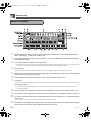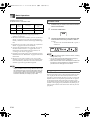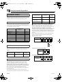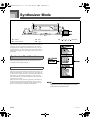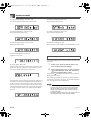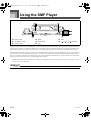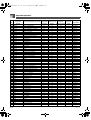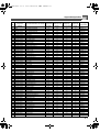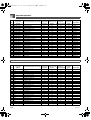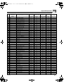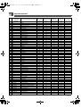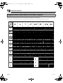
1
CTK691ES01-01_cover1-4.fm 1 ページ 2003年9月29日 月曜日 午後4時56分 CTK691ES01-01_cover1-4.fm 2 ページ 2003年10月23日 木曜日 午後5時2分 CTK691E01-01.book 1 ページ 2003年9月29日 月曜日 午後4時47分 Safety Precautions Safety Precautions Congratulations on your selection of the CASIO electronic musical instrument. Before using the instrument, be sure to carefully read through the instructions contained in this manual. Alkaline Batteries Please keep all information for future reference. Perform the following steps immediately if fluid leaking from alkaline batteries ever gets into your eyes. Symbols Various symbols are used in this user’s guide and on the product itself to ensure that the product is used safely and correctly, and to prevent injury to the user and other persons as well as damage to property. Those symbols along with their meanings are shown below. 1. Do not rub your eyes! Rinse them with water. 2. Contact your physician immediately. Leaving alkaline battery fluid in your eyes can lead to loss of sight. DANGER This symbol indicates information that, if ignored or applied incorrectly, creates the danger of death or serious personal injury. WARNING This indication stipulates matters that have the risk of causing death or serious injury if the product is operated incorrectly while ignoring this indication. CAUTION This indication stipulates matters that have the risk of causing injury as well as matters for which there is the likelihood of occurrence of physical damage only if the product is operated incorrectly while ignoring this indication. Smoke, Strange Odor, Overheating Continued use of the product while it is emitting smoke, a strange odor, or heat creates the risk of fire and electric shock. Take the following steps immediately. 1. Turn off power. 2. If you are using the AC adaptor for power, unplug it from the wall outlet. 3. Contact your original retailer or an authorized CASIO Service Provider. AC Adaptor Symbol Examples This triangle symbol ( ) means that the user should be careful. (The example at left indicates electrical shock caution.) This circle with a line through it ( ) means that the indicated action must not be performed. Indications within or nearby this symbol are specifically prohibited. (The example at left indicates that disassembly is prohibited.) Misuse of the AC adaptor creates the risk of fire and electric shock. Always make sure you observe the following precautions. Be sure to use only the AC adaptor that is specified for this product. Use only a power source whose voltage is the within the rating marked on the AC adaptor. Do not overload electrical outlets and extension cords. The black dot ( ) means that the indicated action must be performed. Indications within this symbol are actions that are specifically instructed to be performed. (The example at left indicates that the power plug must be unplugged from the electrical socket.) 705A-E-003A E-1 CTK691E01-01.book 2 ページ 2003年9月29日 月曜日 午後4時47分 Safety Precautions AC Adaptor Water and Foreign Matter Misuse of the AC adaptor’s electric cord can damage or break it, creating the risk of fire and electric shock. Always make sure you observe the following precautions. Water, other liquids, and foreign matter (such as pieces of metal) getting into the product create the risk of fire and electric shock. Take the following steps immediately. Never place heavy objects on the cord or subject it to heat. Never try to modify the cord or subject it to excessive bending. 1. Turn off power. 2. If you are using the AC adaptor for power, unplug it from the wall outlet. 3. Contact your original retailer or an authorized CASIO Service Provider. Never twist or stretch the cord. Should the electric cord or plug become damaged, contact your original retailer or authorized CASIO Service Provider. AC Adaptor Never touch the AC adapter while your hands are wet. Doing so creates the risk of electric shock. Disassembly and Modification Never try to take this product apart or modify it in any way. Doing so creates the risk of electric shock, burn injury, or other personal injury. Leave all internal inspection, adjustment, and maintenance up to your original retailer or authorized CASIO Service Provider. Dropping and Impact Batteries Misuse of batteries can cause them to leak, resulting in damage to nearby objects, or to explode, creating the risk of fire and personal injury. Always make sure you observe the following precautions. Continued use of this product after it has been damaged by dropping or subjecting it to strong impact creates the risk of fire and electric shock. Take the following steps immediately. 1. Turn off power. Never try to take batteries apart or allow them to become shorted. 2. If you are using the AC adaptor for power, unplug it from the wall outlet. Never expose batteries to heat or dispose of them by incineration. 3. Contact your original retailer or an authorized CASIO Service Provider. Never mix old batteries with new ones. Plastic Bags Never mix batteries of different types. Never place the plastic bag the product comes in over your head or in your mouth. Doing so creates the risk of suffocation. Particular care concerning this precaution is required where small children are present. Do not charge the batteries. Make sure the positive (+) and negative (–) ends of the batteries are facing correctly. Do not incinerate the product. Never throw the product into fire. Doing so can cause it to explode, creating the risk of fire and personal injury. E-2 Keep off of the product and stand.* Climbing onto the product or stand can cause it to tip over or become damaged. Particular care concerning this precaution is required where small children are present. 705A-E-004A CTK691E01-01.book 3 ページ 2003年9月29日 月曜日 午後4時47分 Safety Precautions Location Batteries Avoid locating the product on an unstable stand, on an uneven surface, or any other unstable location. An unstable location can cause the product to fall over, creating the risk of personal injury. Misuse of batteries can cause them to leak resulting in damage to nearby objects, or to explode, creating the risk of fire and personal injury. Always make sure you observe the following precautions. Use only batteries that are specified for use with this product. AC Adaptor Misuse of the AC adaptor creates the risk of fire and electric shock. Always make sure you observe the following precautions. Do not locate the electric cord near a stove or other sources of heat. Never pull on the cord when unplugging from the electrical outlet. Always grasp the AC adaptor when unplugging. AC Adaptor Misuse of the AC adaptor creates the risk of fire and electric shock. Always make sure you observe the following precautions. Insert the AC adaptor into the wall outlet as far as it will go. Unplug the AC adaptor from the wall outlet during lightening storms or before leaving on a trip or other long-term absence. At least once a year, unplug the AC Adaptor from the wall outlet and wipe away any dust that is built up in the area around the prongs of the plug. Relocating the Product Before relocating the product, always unplug the AC adaptor from the wall outlet and disconnect all other cables and connecting cords. Leaving cords connected creates the risk of damage to the cords, fire, and electric shock. Cleaning Before cleaning the product, always unplug the AC adaptor from the wall outlet first. Leaving the AC adaptor plugged in creates the risk of damage to the AC adaptor, fire, and electric shock. 705A-E-005A Remove batteries from the product if you do not plan to use it for a long time. Connectors Connect only the specified devices and equipment to the product’s connectors. Connection of a non-specified device or equipment creates the risk of fire and electric shock. Location Avoid the following locations for this product. Such locations create the risk of fire and electric shock. Areas subject to high humidity or large amounts of dust In food preparation areas or other areas subject to oil smoke Near air conditioning equipment, on a heated carpet, in areas exposed to direct sunlight, inside of a vehicle parked in the sun, or any other area that subjects the product to high temperatures Display Screen Never push on the display screen’s LCD panel or subject it to strong impact. Doing so can cause the LCD panel’s glass to crack, creating the risk of personal injury. Should the LCD panel ever crack or break, never touch the liquid inside of the panel. LCD panel liquid can cause skin irritation. Should LCD panel liquid ever get inside your mouth, immediately wash out your mouth with water and contact your physician. Should LCD panel liquid ever get into your eyes or onto your skin, rinse with clear water for at least 15 minutes, and then contact a physician. E-3 CTK691E01-01.book 4 ページ 2003年9月29日 月曜日 午後4時47分 Safety Precautions Sound Volume Do not listen to music at very loud volumes for long periods. Particular care concerning this precaution is required when using headphones. High volume settings can damage your hearing. Heavy Objects Never place heavy object on top of the product. Doing so can make the product top heavy, causing the product to tip over or the object to fall from it, creating the risk of personal injury. Correct Stand* Assembly An incorrectly assembled stand can tip over, causing the product to fall and creating the risk of personal injury. Make sure you assemble the stand correctly, following the assembly instructions that come with it. Make sure you mount the product on the stand correctly. * Stand is available as an option. When using batteries, be sure to replace them or shift to one of the alternate power sources whenever you notice any of the following symptoms. E-4 Dim power indicator Instrument does not turn on Display that is flickering, dim, or difficult to read Abnormally low speaker/headphone volume Distortion of sound output Occasional interruption of sound when playing at high volumes Sudden power failure when playing at high volumes Flickering or dimming of the display when playing at high volume Continued sound output even after you release a key A tone that is totally different from the one that is selected Abnormal rhythm pattern and demo tune play Loss of power, sound distortion, or low volume when playing from a connected computer or MIDI device 705A-E-006A CTK691E01-01.book 5 ページ 2003年9月29日 月曜日 午後4時47分 Introduction Introduction Congratulations upon your selection of this CASIO musical instrument. This keyboard provides you with the following features and functions. J 516 Tones Include Rich Advanced Tones A total of 300 Advanced Tones are programmed with DSP tones to make them richer and more powerful. Advanced tones like Stereo Piano and Tremolo Electric Piano enhance the Piano and Electric Piano tones to create a totally new sound. J 50 Drawbar Organ Tones In addition to the 516 standards tones, the keyboard also includes 50 realistic drawbar organ tones. Drawbar organ tones can be controlled using nine digital drawbars. You can also select percussion or key click, and even edit the parameters of preset tone and save up to 100 original tones in user tone memory. J Flash Memory Built-in Flash memory lets you expand your selection of tones and rhythms by downloading data from the CASIO MUSIC SITE, or from other sources. You can also store up to 200 SMF format music files for playback. J PIANO SETTING Button The press of a button optimizes the keyboard setup for piano play. J 140 Preset Rhythms + 16 User Rhythms A selection of 140 rhythms includes accompaniments for everything from rock to pops and jazz. You can also transfer accompaniment data from your computer and store up to 16 of them as user rhythms in keyboard memory. J Auto Accompaniment Simply play a chord and the corresponding rhythm, bass and chord parts play automatically. One-touch Preset instantly recalls the most suitable tone and tempo settings to match the rhythm you are using. J Big, Information-packed Display A big built-in display shows chord names, tempo setting, keyboard information, staff notation of notes played, and more for full support of all your keyboard play. A built-in backlight keeps the display easy to read, even in total darkness. J Song Memory Record up to six parts in memory, along with their tone, volume, pan position, and other parameters for later playback. Realistic ensemble play can also be created using the Auto Accompaniment function. J Synthesizer Mode Edit built-in sounds to produce your own original creations. Up to 120 of your own sounds can be stored in memory for recall, just like the built-in tones. J General MIDI compatibility The General MIDI tones of this keyboard let you connect to a personal computer to enjoy “desktop music” capabilities. This keyboard can be used as a desktop music input device or sound source, and it's just the thing for playback of commercially available pre-recorded General MIDI music software. J Powerful effects A collection of powerful effects, such as DSP, reverb, chorus, and more, give you total control over the type of sound you want. You can even change the parameters of an effect to create your own, original effects. A 4-band equalizer is also included. J Mixer You can specify tone, volume, pan position, and other parameters for each built-in Auto Accompaniment part. You can also control the same parameters for each channel during MIDI input. 705A-E-007B E-5 CTK691E01-01.book 6 ページ 2003年9月29日 月曜日 午後4時47分 Introduction J Registration Memory Keyboard setups can be stored in memory for later recall and instant set up whenever you need them. Up to 32 setups (4 setups x 8 banks) can be stored in registration memory. J Data download from your computer You can use your computer to download data from the CASIO MUSIC SITE. E-6 705A-E-008A CTK691E01-01.book 7 ページ 2003年9月29日 月曜日 午後4時47分 Contents Safety Precautions ........ E-1 Introduction ................... E-5 Selecting a DSP Type ........................ E-26 DSP Button......................................... E-28 Selecting REVERB ............................. E-28 General Guide ................ E-9 Selecting CHORUS ............................ E-29 Attaching the Score Stand ..................E-10 Using the Equalizer ............................ E-30 Playing a Demo Tune..........................E-11 Auto Accompaniment ... E-31 About the display.................................E-12 About the MODE button ..................... E-31 Power Supply .............. E-14 Selecting a Rhythm ............................ E-32 Using batteries ....................................E-14 Playing a Rhythm ............................... E-32 Using the AC Adaptor .........................E-15 Adjusting the Tempo .......................... E-32 Auto Power Off....................................E-16 Using Auto Accompaniment ............... E-33 Turning Off the Keyboard ....................E-16 Using an Intro Pattern ........................ E-35 Memory Contents................................E-16 Using a Fill-in Pattern ......................... E-35 Connections ................ E-17 Basic Operations ......... E-19 To play the keyboard...........................E-19 Selecting a Tone .................................E-19 PIANO SETTING Button .....................E-21 Using the Drawbar Organ Mode ................. E-22 To select a drawbar organ tone ..........E-23 To edit a drawbar organ tone ..............E-23 Parameter Details ...............................E-24 To save an edited drawbar organ tone .....................................................E-25 Using a Rhythm Variation................... E-36 Synchro Starting Accompaniment with Rhythm Play................................ E-36 Finishing with an Ending Pattern........ E-36 Using One-touch Preset ..................... E-37 Using Auto Harmonize ....................... E-37 Adjusting the Accompaniment Volume ............................................... E-38 Mixer Function ............. E-39 What you can do with the Mixer ......... E-39 Turning Channels On and Off ............ E-40 Using the Parameter Edit Mode ......... E-40 How Parameters Work ....................... E-41 Applying Effects to Tones ............................ E-26 Synthesizer Mode ........ E-44 Effect Blocks .......................................E-26 Creating a User Tone ......................... E-47 705A-E-009A Synthesizer Mode Functions .............. E-44 E-7 CTK691E01-01.book 8 ページ 2003年9月29日 月曜日 午後4時47分 Contents Storing a User Tone In Memory ..........E-49 Registration Memory .. E-50 Registration Memory Features............E-50 To Save a Setup in Registration Memory ...............................................E-51 To Recall a Setup from Registration Memory ...............................................E-52 Song Memory Function ....................... E-53 Using the SMF Player .......................... E-76 Playing Back an SMF ......................... E-78 Configuring Other Settings ................. E-78 MIDI ............................... E-80 What is MIDI?..................................... E-80 General MIDI ...................................... E-80 Sending and Receiving MIDI Messages ........................................... E-81 Tracks .................................................E-53 MIDI Settings...................................... E-81 Basic Song Memory operations ..........E-54 Using the Data Download Service...... E-82 Using Real-time Recording .................E-54 Mixer Mode Settings ...........................E-55 Troubleshooting .......... E-83 Playing Back from Song Memory........E-56 Specifications .............. E-85 Recording Melody and Chords with Step Recording ............................E-56 Care of your Instrument .................... E-87 Recording Multiple Tracks...................E-59 Correcting Mistakes While Step Recording............................................E-61 DSP Algorithm List ...... E-88 Editing Memory Contents....................E-62 Appendix ........................A-1 Editing a Song.....................................E-64 Tone List............................................... A-1 Keyboard Settings ...... E-66 Drum Assignment List ....................... A-12 Using Layer .........................................E-66 Using Split ...........................................E-67 Using Layer and Split Together...........E-68 Transposing the Keyboard ..................E-69 Rhythm List ........................................ A-14 Fingered Chord Chart......................... A-16 Effect List............................................ A-18 MIDI Implementation Chart Using Touch Response.......................E-69 Tuning the Keyboard...........................E-70 Changing Other Settings.....................E-71 E-8 705A-E-010A CTK691E01-01.book 9 ページ 2003年9月29日 月曜日 午後4時47分 General Guide General Guide 705A-E-011A E-9 CTK691E01-01.book 10 ページ 2003年9月29日 月曜日 午後4時47分 General Guide 1 POWER button cl SPLIT button 2 Power indicator cm LAYER button 3 SONG MEMORY button cn [ 4 SYNTH button co DEMO button (*3) 5 TRANSPOSE/FUNCTION button cp Speaker 6 MIXER button cq Rhythm list 7 EFFECT button cr Tone list 8 SMF PLAYER button cs Display 9 VOLUME knob ct CHORD root names bk MODE button dk Percussion instrument list bl ONE TOUCH PRESET button dl Chord types name bm ACCOMP VOLUME button dm INTRO/ENDING 1/2 buttons bn DATA ACCESS indicator dn VARIATION/FILL-IN 1/2 buttons bo RHYTHM button do SYNCHRO/FILL-IN NEXT button bp TONE button dp START/STOP button bq DRAWBAR ORGAN button dq TEMPO buttons br DSP button dr REGISTRATION buttons ]/[ ]/[ ]/[ bs PIANO SETTING button a) BANK button bt EXIT button b) STORE button ck AUTO HARMONIZE button ]CURSOR buttons ds SONG MEMORY TRACK buttons J Attaching the Score stand (*1) Insert the score stand into the slot at the top of the keyboard as shown in the illustration. E-10 705A-E-012A CTK691E01-01.book 11 ページ 2003年9月29日 月曜日 午後4時47分 General Guide *2 dt Number buttons For input of numbers to change displayed settings. ek [+]/[–] buttons (YES/NO) Negative values can be changed only by using [+] and [–] to increment and decrement the displayed value. Rear Panel el MIDI OUT terminal em MIDI IN terminal en SUSTAIN/ASSIGNABLE JACK terminal eo PHONES/OUTPUT terminal ep DC 9V jack J Playing a Demo Tune (*3) Pressing the DEMO button starts demo tune play. There are 3 demo tunes, which continuously play in sequence. To stop demo tune play, press either the DEMO button or the START/STOP button. Pressing the [+]/[–] buttons skips to the next demo tune. The PIANO SETTING button, Layer, and Split are disabled while a demo tune is playing. 705A-E-013C E-11 CTK691E01-01.book 12 ページ 2003年9月29日 月曜日 午後4時47分 General Guide About the display 1. 2. 3. Pointers appear here to show when Transpose, the Keyboard Setting Mode, the Mixer Mode, Synthesizer, Effect, Song Memory, or SMF player is being used. The TONE indicator appears when you are selecting or viewing the TONE setting, while RHYTHM appears for the RHYTHM setting. Tone number (Numeric Area)/Tone name (Text Area) The numeric area and text area are also used to indicate the rhythm number and rhythm name, and to indicate various functions in the Synthesizer Mode, Mixer Mode, Registration Mode, and Song Memory Mode. 4. Octave Symbol Appears when the note produced by the keyboard is one octave higher than the note indicated on the staff. 5. 6. 7. Notes you play on the keyboard, notes being played back from Song Memory, chord forms, and received MIDI data* are shown in the staff on the display. Pointers appear here to show when the layer, split, or auto harmonize is being used. Level Meter The velocity of each channel is indicated as one of three levels. This display also shows the Mixer channel’s on/off status. Drawbar Organ Mode In the Drawbar Organ Editing Mode, the level meter shows the position of each drawbar and the status of each percussion parameter. 8. 9. 10. The beat number is indicated while a rhythm, Auto-accompaniment, or Song Memory Mode is being used. The measure number is indicated while a rhythm, Auto-accompaniment, or Song Memory Mode is being used. The number of beats per minute are indicated while a rhythm, Auto-accompaniment, or Song Memory Mode is being used. The tempo area is also used to indicate the Song Memory function’s clock. 11. E-12 REC flashes on the display during Song Memory record standby. REC remains on the display without flashing while recording is in progress. STEP is displayed during step recording. 705A-E-014A CTK691E01-01.book 13 ページ 2003年9月29日 月曜日 午後4時47分 General Guide 12. 13. 14. You can turn on the metronome to provide a reference beat for your keyboard play. This display shows the note played on the keyboard, notes being played back from Song Memory, chord forms, and received MIDI data*. The name of the chord being played is shown on the display while Auto Accompaniment is being used. * These items do not appear when a note outside the display range (C2 to C7) is received. Display examples shown in this User’s Guide are intended for illustrative purposes only. The actual text and values that appear on the display may differ from the examples shown in this User’s Guide. Due to LCD element characteristics, display contrast changes depending on the angle from which you view it. The initial default contrast setting is one that allows easy viewing for a musician seated directly in front of the display. You can also adjust the contrast to the level that suits your particular needs. For more information, see page E-74. 705A-E-015A E-13 CTK691E01-01.book 14 ページ 2003年9月29日 月曜日 午後4時47分 Power Supply Power Supply This keyboard can be powered by current from a standard household wall outlet (using the specified AC adaptor) or by batteries. Always make sure you turn the keyboard off whenever you are not using it. Using batteries Always make sure you turn off the keyboard before loading or replacing batteries. To load batteries 1. Important Battery Information The following shows the approximate battery life. Manganese batteries: Approximately 4 hours The above value is standard battery life at normal temperature, with the keyboard volume at a medium setting. Temperature extremes or playing at very loud volume settings can shorten battery life. Any of the following symptoms indicate low battery power. Replace batteries as soon as possible whenever any of the following occurs. Dim power indicator Instrument does not turn on Remove the battery compartment cover. Display that is flickering, dim, or difficult to read Abnormally low speaker/headphone volume Distortion of sound output Occasional interruption of sound when playing at high volumes Sudden power failure when playing at high volumes 2. Flickering or dimming of the display when playing at high volume Load six D-size batteries into the battery compartment. Make sure that the positive (+) and negative (–) ends are facing correctly. Continued sound output even after you release a key A tone that is totally different from the one that is selected. Abnormal rhythm pattern and demo tune play Loss of power, sound distortion, or low volume when playing from a connected computer or MIDI device 3. Insert the tabs on the battery compartment cover into the holes provided and close the cover. Misuse of batteries can cause them to leak, resulting in damage to nearby objects, or to explode, creating the risk of fire and personal injury. Always make sure you observe the following precautions Never try to take batteries apart or allow them to become shorted. Never expose batteries to heat or dispose of them by incineration. 1 Tab Never mix old batteries with new ones. Never mix batteries of different types. Do not charge the batteries. The keyboard may not function correctly if you load or replace batteries with power turned on. If this happens, turning the keyboard off and then back on again should return functions back to normal. E-14 Make sure the positive (+) and negative (–) ends of the batteries are facing correctly. 705A-E-016A CTK691E01-01.book 15 ページ 2003年9月29日 月曜日 午後4時47分 Power Supply Misuse of batteries can cause them to leak resulting in damage to nearby objects, or to explode, creating the risk of fire and personal injury. Always make sure you observe the following precautions Use only batteries that are specified for use with this product. Remove batteries from the product if you do not plan to use it for a long time. Misuse of the AC adaptor creates the risk of fire and electric shock. Always make sure you observe the following precautions. Be sure to use only the AC adaptor that is specified for this product. Use only a power source whose voltage is within the rating marked on the AC adaptor. Do not overload electrical outlets and extension cords. Never place heavy objects on the cord or subject it to heat. Using the AC Adaptor Make sure that you use only the AC adaptor specified for this keyboard. Specified AC Adaptor: AD-5 Never try to modify the cord or subject it to excessive bending. Never twist or stretch the cord. Should the electric cord or plug become damaged, contact your original retailer or authorized CASIO Service Provider. Never touch the AC adaptor while your hands are wet. Doing so creates the risk of electric shock. Rear Panel Misuse of the AC adaptor creates the risk of fire and electric shock. Always make sure you observe the following precautions. Do not locate the electric cord near a stove or other sources of heat. Never pull on the cord when unplugging from the electrical outlet. Always grasp the AC adaptor when unplugging. 1 2 3 DC 9V jack AC adaptor AD-5 AC outlet Also note the following important warnings and precautions when using the AC adaptor. Insert the AC adaptor into the wall outlet as far as it will go. Unplug the AC adaptor from the wall outlet during lightening storms or before leaving on a trip or other long-term absence. At least once a year, unplug the AC adaptor from the wall outlet and wipe away any dust that is built up in the area around the prongs of the plug. Make sure that the keyboard is turned off before connecting or disconnecting the AC adaptor. Using the AC adaptor for a long time can cause it to become warm to the touch. This is normal and does not indicate malfunction. 705A-E-017A E-15 CTK691E01-01.book 16 ページ 2003年9月29日 月曜日 午後4時47分 Power Supply Auto Power Off When you are using battery power, keyboard power turns off automatically whenever you leave it on without performing any operation for about 6 minutes. When this happens, press the POWER button to turn power back on. Auto Power Off is disabled (it does not function) when you are using the AC adaptor to power the keyboard. Turning Off the Keyboard Be sure to press the POWER button to turn off power and make sure that the LCD backlight is off before disconnecting the AC adaptor or doing anything else. Never disconnect the AC adaptor while the keyboard is turned on or try to turn off power using any other technique besides pressing the POWER button. Doing so can cause the contents of the keyboard's Flash memory to become corrupted. Strange keyboard operation and abnormal startup when power is turned on are symptoms of corrupted Flash memory contents. See “Troubleshooting” on page E-83 for more information. To disable Auto Power Off Never press the POWER button while the following message is on the keyboard’s display. (message) “Pls Wait” or “Bulk In” Hold down the TONE button while turning on the keyboard to disable Auto Power Off. Turning off the keyboard while the above message is on the display can cause user data (user tones, song memory data, etc.) currently stored in keyboard memory to become corrupted. Once corrupted, you may not be able to recall the data again. When Auto Power Off is disabled, the keyboard does not turn off automatically no matter how long it is left with no operation being performed. Auto Power Off is automatically enabled whenever you turn on keyboard power. Settings Tone, rhythm, and other “main keyboard settings” in effect when you turn off the keyboard manually by pressing POWER button or when Auto Power Off turns off power are still in effect the next time you turn power back on. Memory Contents In addition to the above settings, data stored in the Registration Mode and Song Memory Mode is also retained when keyboard power is turned off. Saving Setups and Memory Contents J Main Keyboard Settings Tone number, layer, split, split point, drawbar organ tone settings, transpose, tuning, contrast settings, touch response, reverb, chorus, DSP, equalizer, rhythm number, tempo, keyboard channel, MIDI In Chord Judge on/off, accomp MIDI out on/off, assignable jack setting, accompaniment volume, user area tones (Synthesizer Mode), user area accompaniments, user DSP area, Auto Harmonize on/off, Auto Harmonize type, Mixer hold, DSP hold, Auto Accompaniment mode, all Mixer parameters, all Synthesizer Mode parameters, Song Memory song numbers, SMF player settings (play mode, manual play part, SMF playback volume) About Flash memory Your keyboard comes with built-in Flash memory, which can continue to hold data even when electrical power is totally cut off. This means that even after batteries go completely dead, you can attach the AC adaptor, turn on power, and still recall data stored in memory. When running under battery power, be sure to replace batteries as soon as possible after the first signs of low battery power (dim power indicator lamp, dim display characters, etc.) Though the keyboard’s Flash memory is non-volatile (which means that data is not lost when power is interrupted), data can be lost if power suddenly fails while data is being written to flash memory*. * While storing or deleting user data, while recording with the synthesizer, while transferring data from a computer, etc. Initializing the Keyboard Use the procedure on page E-75 to initialize the keyboard, which clears all memory data and returns settings to their initial factory defaults. E-16 705A-E-018A CTK691E01-01.book 17 ページ 2003年9月29日 月曜日 午後4時47分 Connections Connections Phones/Output Terminal Connection Example Before connecting phones or other external equipment, be sure to first turn down the volume settings of the keyboard and the connected equipment. You can then adjust volume to the desired level after connections are complete. Rear Panel You can also connect the keyboard to a computer or sequencer. See “MIDI” on page E-80 for details. Sustain/Assignable jack Terminal You can connect an optional sustain pedal (SP-2 or SP-20) to the SUSTAIN/ASSIGNABLE JACK terminal to enable the capabilities described below. For details on how to select the pedal function you want, see “Changing Other Settings” on page E-71. J Connecting Phones 1 Connecting phones cuts off output from the keyboard’s builtin speakers, so you can play even late at night without disturbing anyone. J Audio Equipment 2 Connect the keyboard to a audio equipment using a commercially available connecting cord with a standard plug on one end and two PIN plugs on the other end. Note that the standard plug you connect to the keyboard must be a stereo plug, otherwise you will be able to output only one of stereo channels. In this configuration, you normally set the input selector of the audio equipment to the terminal (usually marked AUX IN or something similar) where the cord from the keyboard is connected. See the user documentation that comes with your audio equipment for full details. J Musical Instrument Amplifier 3 Use a commercially available connecting cord to connect the keyboard to a musical instrument amplifier. Be sure to use a connecting cord that has a stereo standard plug on the end you connect to the keyboard, and a connector that provides dual channel (left and right) input to the amplifier to which you are connecting. The wrong type of connector at either end can cause one of the stereo channels to be lost. When connected to a musical instrument amplifier, set the volume of the keyboard to a relatively low level and make output volume adjustments using the amplifier’s controls. 705A-E-019A 1 SUSTAIN/ASSIGNABLE JACK Terminal, J Sustain Pedal With piano tones, depressing the pedal causes notes to linger, much like a piano’s damper pedal. With organ tones, depressing the pedal causes notes to continue to sound until the pedal is released. J Sostenuto Pedal As with the sustain pedal function described above, depressing the sostenuto pedal causes notes to be sustained. This difference between a sostenuto pedal and sustain pedal is the timing. With a sostenuto pedal, you press the keys and then depress the pedal before you release the keys. Only the notes that are sounding when the pedal is depressed are sustained. E-17 CTK691E01-01.book 18 ページ 2003年9月29日 月曜日 午後4時47分 Connections J Soft Pedal Depressing the pedal softens the sound of the notes being played. J Rhythm Start/Stop Pedal In this case, the pedal performs the same functions as the START/STOP button. Accessories and Options Use only the accessories and options specified for this keyboard. Use of non-authorized items creates the danger of fire, electrical shock, and personal injury. E-18 705A-E-020A CTK691E01-01.book 19 ページ 2003年9月29日 月曜日 午後4時47分 Basic Operations Basic Operations 1 VOLUME 2 POWER 3 TONE 4 7 DSP 5 8 PIANO SETTING 6 START/STOP Number buttons [+]/[–] This section provides information on performing basic keyboard operations. To play the keyboard 1. 2. 3. Press the POWER button to turn the keyboard on. Use the VOLUME knob to set the volume to a relatively low level. Play something on the keyboard. Selecting a Tone This keyboard comes with tones built-in, as shown below. A partial list of the available tone names is printed on the keyboard console. See the “Tone List” on page A-1 of this manual for a complete list. “Advanced Tones” are variations of standard tones, which are created by programming in effects (DSP) and other settings. For details about drawbar organ tones, see “Using the Drawbar Organ Mode” on page E-22. Tone Types Standard Tones: 516 Preset Tones + 124 User Tones 705A-E-021A Number Number of Tones 000-299 300 Advanced Tones On 300-499 200 Preset Tones Off 500-515 16 Drum Sets Off 600-699 100 User Tones (*2) On/Off (*3) 700-719 20 User Tones with Waves (*4) On/Off (*3) 800-803 4 User Drum Sets with Waves (*4) On/Off (*5) Tone Type DSP Line On/Off (*1) E-19 CTK691E01-01.book 20 ページ 2003年9月29日 月曜日 午後4時47分 Basic Operations Drawbar Organ Tones: 50 Preset Tones + 100 User Tones To select a tone Number Number of Tones 000-049 50 Preset Tones On/Off (*5) 100-199 100 User Tones (*6) On/Off (*3) Tone Type DSP Line On/Off (*1) *1: See “Changing Tones and Configuring DSP Effect Settings” on page E-21. *2: Memory area for tones created by you. See “Synthesizer Mode” on page E-44. User tone areas 600 through 699 initially contain the same data as DSP types 000 through 099. *3: Depends on source tone or user setting. See “Synthesizer Mode” on page E-44 for more information. 1. 2. 3. Find the tone you want to use in the tone list and note its tone number. Press the TONE button. Use the number buttons to input the three digit tone number for the tone you want to select. Example: To select “332 ACOUSTIC BASS GM”, input 3, 3 and then 2. *4: Area for data transferred from a computer. See “Using the Data Download Service” on page E-82 for more information. For information about waveforms, see “Creating a User Tone” on page E-47. *5: Depends on tone. This status can be checked by viewing the DSP button. See “DSP Button” on page E-28 for more information. *6: Memory area for tones created by you. See “To edit a drawbar organ tone” on page E-23. User drawbar organ tone areas initially contain two sets of the same data as drawbar organ tones types 000 through 049. You cannot select tone numbers not included in the above ranges (standard tones 516 through 599 and 720 through 799, and drawbar organ tones from 050 to 099). When you use the [+] and [–] buttons to scroll through tone numbers, scrolling jumps across the unused numbers. Pressing [+] when 515 is selected, for example, jumps to 600. E-20 Always input all three digits for the tone number, including leading zeros (if any). You can also increment the displayed tone number by pressing [+] and decrement it by pressing [–]. When one of the drum sets is selected (tone numbers 500 through 515), each keyboard key is assigned a different percussion sound. See page A-12 for details. Polyphony The term polyphony refers to the maximum number of notes you can play at the same time. The keyboard has 32-note polyphony, which includes the notes you play as well as the rhythms and auto-accompaniment patterns that are played by the keyboard. This means that when a rhythm or autoaccompaniment pattern is being played by the keyboard, the number of notes (polyphony) available for keyboard play is reduced. Also note that some of the tones offer only 10-note polyphony. 705A-E-022A CTK691E01-01.book 21 ページ 2003年9月29日 月曜日 午後4時47分 Basic Operations J Digital Sampling A number of the tones that are available with this keyboard have been recorded and processed using a technique called digital sampling. To ensure a high level of tonal quality, samples are taken in the low, mid, and high ranges and then combined to provide you with sounds that are amazingly close to the originals. You may notice very slight differences in volume or sound quality for some tones when you play them at different positions on the keyboard. This is an unavoidable result of multiple sampling, and it is not a sign of malfunction. Changing Tones and Configuring DSP Effect Settings This keyboard has only a single DSP sound source. Because of this, selecting tones for which DSP is enabled for multiple parts when layering or splitting tones (page E-66, 67) can cause conflicts. To avoid conflicts, DSP is allocated to the last DSP enabled tone, and DSP is disabled (DSP line OFF) for all other parts. DSP line is a parameter that controls whether or not the currently selected DSP effect is applied to a part.* Each tone has a DSP line parameter. Selecting a tone for a part applies the tone’s DSP line parameter setting to all parts. To optimize keyboard settings for piano play 1. 2. Press the PIANO SETTING button. Now try playing something on the keyboard. The notes you play will sound with a piano tone. 3. If you want to play with rhythm accompaniment, press the START/STOP button. This causes a rhythm that is optimized for piano will start to play. To stop rhythm play, press the START/STOP button again. Pressing the PIANO SETTING button while a rhythm is playing stops rhythm play and then changes the keyboard setup. Pressing the PIANO SETTING button while the keyboard is in the Synthesizer Mode or other mode exits the current mode and then changes the keyboard setup. The setup of the keyboard does not change if you press the PIANO SETTING button when any one of the following exists. * During real-time recording, step recording, or while using the editing function of the Song Memory * While the data save or overwrite message is on the display * During a registration data save operation * The DSP line parameter is turned on (DSP effect is applied) for the 300 Advanced Tones numbered 000 through 299, and turned off (DSP effect not applied) for the 200 preset tones from 300 to 499. For information about other tones, see “Tone Types” on page E-19. PIANO SETTING Button Pressing this button changes the setup of the keyboard to optimize it for piano play. Settings Tone number: Rhythm number: Accompaniment Mode: Layer: Split: Auto Harmonize: Transpose: Touch Response: Assignable Jack: Local Control: Mixer Channel 1 Parameter Setup: 705A-E-023A “000 St.GrPno” “120 Pf Bld 1” Normal Off Off Off 0 Off: Returns to initial default On: No change SUS On Depends on tone E-21 CTK691E01-01.book 22 ページ 2003年9月29日 月曜日 午後4時47分 Using the Drawbar Organ Mode Using the Drawbar Organ Mode 1 DRAWBAR ORGAN 2 [ 4 Number buttons 5 [+]/[–] ]/[ ]/[ ]/[ ] CURSOR 3 EXIT Your keyboard has built-in “drawbar organ tones” that can be altered using nine digital drawbars whose operations are similar to the controls on a drawbar organ. You can also select percussion or key click. There is room in memory for storage of up to 100 usercreated drawbar tone variations. Drawbar Organ Mode Operational Flow * You can also display the drawbar organ tone selection screen from the Song Memory Mode or SMF Playback Mode screen. In this case, however, the Drawbar Organ Tone Editing Screen does not appear. E-22 705A-E-024A CTK691E01-01.book 23 ページ 2003年9月29日 月曜日 午後4時47分 Using the Drawbar Organ Mode There are a total of 13 parameters. You can use the [ ] and [ ] CURSOR buttons to cycle through them. See “Parameter Details” on page E-24 for more information. To select a drawbar organ tone 1. 2. Find the drawbar organ tone you want to use in the tone list and note its tone number. While the “More?” screen is on the display, you can advance to the synthesizer and DSP effect editing screens by pressing the [ ] CURSOR button or the [+] button. Press the DRAWBAR ORGAN button. This causes the drawbar organ tone selection screen to appear. 3. Use the [ ] and [ ] CURSOR buttons or the [+] and [–] buttons to change the setting of the currently displayed parameter. You can also change a parameter setting by entering a value with the number buttons. You can monitor the changes in a tone by playing notes on the keyboard as you adjust parameter settings. 1 2 3. Tone Number Tone Name Use the number buttons to input the three digit tone number for the tone you want to select. Always input all three digits for the tone number, including leading zeros (if any). You can also increment the displayed tone number by pressing [+] and decrement it by pressing [–]. Selecting a different tone after you edit parameters replaces parameter settings with those of the newly selected tone. If you have drawbar organ tones assigned to more than one channel, changing the drawbar organ tone setting for one of the channels causes the same setting to be applied to all of the other channels as well. See “To save an edited drawbar organ tone” on page E-25 for information about saving your edits. Editing Synthesizer Mode Parameters and DSP Parameters of Drawbar Organ Tones To edit a drawbar organ tone 1. 2. Select the drawbar organ tone (000 to 049, 100 to 199) you want to edit. Use the [ ] and [ ] CURSOR buttons to display the drawbar organ tone editing screen. Select the parameter whose setting you want to change. Example: Selecting the “Ft16’” parameter As with standard (non-drawbar) tones, you can edit the Synthesizer Mode parameters and DSP parameters of drawbar organ tones (See “Drawbar Organ Mode Operational Flow” on page E-22). 1. Use the [ ] and [ ] CURSOR buttons to display “More?”, and then press the [ ] CURSOR button. This enters the Synthesizer Mode, which is indicated by the pointer next to SYNTH on the display screen. For the remainder of this procedure, perform the steps starting from step 3 under “Creating a User Tone” on page E-47. 1 2 705A-E-025A Parameter Setting Parameter Name E-23 CTK691E01-01.book 24 ページ 2003年9月29日 月曜日 午後4時47分 Using the Drawbar Organ Mode Parameter Details The following provides details about the parameters you can configure using the drawbar organ tone editing screen. Drawbar Position This parameter defines the position of each drawbar, and the volume of each overtone. The larger the value, the greater the corresponding overtone’s volume. Parameter Display Indication Parameter Name Parameter Display Indication Parameter Name Settings Drawbar 16’ Ft16’ 0 to 3 Drawbar 5 1/3’ Ft 5 1/3’ 0 to 3 Drawbar 8’ Ft 8’ 0 to 3 Drawbar 4’ Ft 4’ 0 to 3 Drawbar 2 2/3’ Ft 2 2/3’ 0 to 3 Drawbar 2’ Ft 2’ 0 to 3 Drawbar 1 3/5’ Ft 1 3/5’ 0 to 3 Drawbar 1 1/3’ Ft 1 1/3’ 0 to 3 Drawbar 1’ Ft 1’ 0 to 3 2nd Percussion oFF: Off Second 3rd Percussion Third Percussion Decay Time Decay Settings on: On oFF: Off on: On 000 to 127 J Display Contents in the Drawbar Organ Mode In the Drawbar Organ Mode, the current status of the drawbar positions, key click, and percussion parameters are indicated on the display’s bar graph as shown in the illustrations below. There is one line for each parameter, and the bottom segment of the selected parameter line flashes. The bottom segment of the bar graph column that represents the currently selected parameter flashes to indicate that it is selected. None of the channel numbers (1 to 16) are displayed in the drawbar organ tone selection mode and editing mode. Drawbar Position Graph Setting Value 0 1 2 3 Display (Ft: Feet) Off On Flash Click The parameter determines whether or not a key click is added when a sustained tone configured using the drawbars is played. Parameter Name Click Setting Value Off On Display Parameter Display Indication Click Click and Percussion On/Off Graph Settings oFF: Click Off on: Click On Percussion Decay Time Graph Setting Value Percussion 0-31 32-63 64-95 96-127 Display This parameter lets you add percussion sound, which provides modulation to sustained tones that you create. When you hold down a key on the keyboard, the sound produced decays until it is no longer audible. Pressing the key again sounds the note again at a louder volume. Percussion has “2nd Percussion” (2nd overtone pitch) and “3rd Percussion” (3rd overtone pitch) settings, each of which can be turned on or off. You can also specify the percussion decay time, which controls how long it takes for the percussion sound to decay. E-24 705A-E-026A CTK691E01-01.book 25 ページ 2003年9月29日 月曜日 午後4時47分 Using the Drawbar Organ Mode To save an edited drawbar organ tone 1. 2. 3. After editing parameters, use the [ ] and [ CURSOR buttons to display “More?”. ] Press the [ ] CURSOR button three times to display the screen for inputting a tone name and assigning a tone number. Use the [+] and [–] buttons to select a tone number. You can select a tone number in the range of 100 to 199. 4. After the tone name is the way you want, press the [ ] CURSOR button to store the tone. Use the [+] and [–] buttons to scroll through letters at the current cursor location. Use the [ ] and [ ] CURSOR buttons to move the cursor left and right. See the page E-49 for information about inputting text. 5. After everything is the way you want, press the [ ] CURSOR button to store the tone. This will display a confirmation message asking whether you really want to save the data. Press the YES button to save the data. After the save operation is complete, the message “Complete” appears and then the display returns to the tone selection or rhythm selection screen. To cancel save, press the EXIT button. 705A-E-027A E-25 CTK691E01-01.book 26 ページ 2003年9月29日 月曜日 午後4時47分 Applying Effects to Tones Applying Effects to Tones 1 EFFECT 4 [ ]/[ ]/[ ]/[ ] CURSOR 2 EXIT 3 DSP 5 Number buttons 6 [+]/[–] This keyboard provides you with a selection of effects that you can apply to tones. The built-in effects include a wide variety of variations that give you access to a selection of general digital effects. Effect Blocks The following shows how the effects of this keyboard are organized. J CHORUS The chorus effect gives sound greater depth by causing it to vibrate. You can choose from among 16 different chorus effects, including “Chorus” and “Flanger.” The equalizer is another type of effect that you can use to make adjustments in tone quality. Frequencies are divided among a number of bands, and raising and lowering the level of each frequency band alters the sound. You can reproduce the optimal acoustics for the type of music you are playing (classics, for example) by selecting the applicable equalizer setting. Selecting a DSP Type J DSP DSP effects are applied to the connection between the sound source and output. You can select distortion and modulation effects. You can create DSP effect setups and also transfer downloaded DSP data from your computer. The keyboard has memory that lets you store up to 100 DSP effect setups. See “Using the Data Download Service” on page E-82 and “Saving the Settings of DSP Parameters” on page E-28 for more information. J REVERB Reverb simulates the acoustics of specific types of environments. You can choose from among 16 different reverb effects, including “Room” and “Hall.” In addition to the 100 built-in effect types, you can also edit effect types to create your own and store them in user memory. You can have up to 100 effect types in user memory at one time. You can also select the DSP type of the last DSP enabled tone that you used. This means you always have access to the DSP type of Advanced Tones and tones you download over the Internet. To select the DSP type of the last DSP enabled tone that you used, select “ton” in step 3 of the procedure below. Perform the following steps to select a DSP type. When using a DSP effect, you should use the Mixer to confirm that the DSP lines of the required parts are turned on. See “Mixer Function” on page E-39 for more information. 1. E-26 Press the EFFECT button so the pointer appears next to EFFECT on the display. 705A-E-028A CTK691E01-01.book 27 ページ 2003年9月29日 月曜日 午後4時47分 Applying Effects to Tones 2. Press the [ ] CURSOR button. The DSP type setting screen will appear automatically about fives seconds after you press the button. 3. Use the [+] and [–] buttons or the number buttons to select the type of DSP you want. See the “Effect List” on page A-18 for information about the DSP types that can be selected. Here you could also change the parameters of the effect you selected, if you want. See “Changing the Settings of DSP Parameters” for more information. The DSP type display area shows the DSP number (000 to 199) or “ton” (user tone created using DSP). Changing the Settings of DSP Parameters You can control the relative strength of a DSP and how it is applied. See the following section titled “DSP Parameters” for more information. 1. After selecting the DSP type you want, use the [ ] and [ ] CURSOR buttons to display the parameter whose setting you want to change. This displays the parameter setting screen. 2. Use the [+] and [–] buttons or the number buttons to make the parameter setting you want. z DSP Reverb Send (Range: 000 to 127) Specifies how much of the post-DSP sound should be sent to reverb. z DSP Chorus Send (Range: 000 to 127) Specifies how much of the post-DSP sound should be sent to chorus. Whether or not an effect is applied to the parts that are sounding also depends on Mixer Mode Reverb Send, Chorus Send, and DSP on/off settings. See “Mixer Function” on page E-39 for more information. Playing a demo tune (page E-11) automatically changes the effect to the one that is assigned to the tune. You cannot change or cancel a demo tune effect. Changing the effect setting while sound is being output by the keyboard causes a slight break in the sound when the effect changes. A number of tones, called “Advanced Tones,” automatically turn on the DSP line for richer, higher quality sound. If you assign an Advanced Tone to a keyboard part (Channels 1 through 4), the DSP line turns on automatically and the DSP selection changes in accordance with the settings of the Advanced Tone. Also, the Mixer Mode DSP line on/off setting for the keyboard part to which the Advanced Tone is assigned is turned on.* * The Mixer DSP line setting is automatically turned off for each part that does not have an Advanced Tone assigned. Because of this, DSP effects previously applied to these parts are cancelled, which can make their tone sound different. In this case, display the Mixer screen and turn DSP back on. Pressing the [+] and [–] buttons at the same time returns the parameter to its recommended setting. 3. Press the EFFECT or EXIT button. This exits the tone or ryhthm setting screen. DSP Parameters The following describes the parameters for each DSP. J DSP z Parameter 0 to 7 These parameters differ in accordance with the algorithm* of the selected DSP type. See the “Effect List” on page A-18 and the “DSP Algorithm List” on page E-88 for more information. * Effector structure and operation type 705A-E-029A E-27 CTK691E01-01.book 28 ページ 2003年9月29日 月曜日 午後4時47分 Applying Effects to Tones Saving the Settings of DSP Parameters You can save up to 100 modified DSPs in the user area for later recall when you need them. User DSP areas 100 through 199 initially contain the same data as DSP types 000 through 099. 1. To turn DSP line on and off 1. Selecting REVERB Perform the following steps to select REVERB. After making the DSP parameter settings you want, press the [ ] CURSOR button. 1. This causes the DSP number of the user area where the DSP will be saved to flash on the display. 2. Press the DSP button to toggle DSP line for the currently selected part on and off. Press the EFFECT button, so the pointer appears next to EFFECT on the display screen. Use the [+] and [–] buttons to select the user DSP area number where you want to save the new DSP. You can select a user DSP area number in the range of 100 to 199 only. 3. After the user DSP area number you want is selected, press the [ ] CURSOR button. Use the [+] and [–] buttons to scroll through letters at the current cursor location. Use the [ ] and [ ] CURSOR buttons to move the cursor left and right. 1 2. After everything is the way you want, press the [ ] CURSOR button to store the effect. This will display a confirmation message asking whether you really want to save the data. Press the YES button to save the data. The message “Complete” appears momentarily on the display, followed by the tone or rhythm selection screen. DSP Button Checking the DSP button will tell you whether or not DSP is enabled for the tone that is currently selected for a part. The DSP button will be lit for a tone that is DSP enabled (DSP line ON), and unlit for a tone that is DSP disabled (DSP line OFF). For example, when you move each part while using the split/ layer function, the DSP button lights or goes out in accordance with that parts setting. Press the [ ] CURSOR button once. This displays the reverb editing screen. 3. Press the [ ] CURSOR button. The reverb type setting screen will appear automatically about fives seconds after you press the button. See the page E-49 for information about inputting text. 4. Pointer 4. Use the [+] and [–] buttons or the number buttons to scroll through the reverb types until the one you want is displayed, or use the number buttons to input the reverb number you want to select. See the list on page A-18 for information about the types of REVERB effects that are available. Here you could also change the parameters of the effect you selected, if you want. See “Changing the Settings of REVERB Parameters” for more information. Changing the Settings of REVERB Parameters You can control the relative strength of a reverb and how it is applied. See the following section titled “REVERB Parameters” for more information. Pressing the DSP button toggles the tone of the part you are currently playing on the keyboard between enabled (DSP line ON) and disabled (DSP line OFF). E-28 705A-E-030B CTK691E01-01.book 29 ページ 2003年9月29日 月曜日 午後4時47分 Applying Effects to Tones 1. After selecting the reverb type you want, use the [ ] and [ ] CURSOR buttons to display the parameter whose setting you want to change. This displays the parameter setting screen. Example: To set the Reverb Time parameter 2. 3. Use the [+] and [–] buttons or the number buttons to input the parameter setting you want. Press the EFFECT or EXIT button. This returns to the tone or rhythm selection screen. z High Damp Same as Reverb Type Whether or not an effect is applied to the parts that are sounding also depends on Mixer Mode Reverb Send, Chorus Send, and DSP on/off settings. See “Mixer Function” on page E-39 for more information. Selecting CHORUS Perform the following steps to select CHORUS. 1. 2. REVERB Parameters z Reverb Level (Range: 000 to 127) 3. 4. z Reverb Time (Range: 000 to 127) This parameter controls the initial reverb volume. The initial echo sound is the first sound reflected from the walls and ceiling when a sound is output by this keyboard. A larger value specifies a larger echo sound. z Delay Level (Range: 000 to 127) Specifies the size of the delay sound. A higher value produces a larger delay sound. z ER Level Same as Reverb Type 705A-E-031A Use the [+] and [–] buttons or the number buttons to scroll through the chorus types until the one you want is displayed, or use the number buttons to input the chorus number you want to select. Changing the Settings of CHORUS Parameters You can control the relative strength of an effect and how it is applied. The parameters you can control depend on the effect. See the following section titled “CHORUS Parameters” for more information. 1. z Delay Feedback (Range: 000 to 127) Adjusts delay repeat. A higher value produces a greater number of repeats. ] CURSOR button. Here you could also change the parameters of the effect you selected, if you want. See “Changing the Settings of CHORUS Parameters” for more information. z ER Level (Initial Echo Sound) (Range: 000 to 127) Delay Type (No. 6, 7, 14, 15) Press the [ See the list on page A-18 for information about the types of CHORUS effects that are available. Controls how long reverb continues. A larger number produces longer reverb. Adjusts the damping of high frequency reverberation (high sound). A smaller value damps high sounds, creating a dark reverb. A larger value does not damp high sounds, for a brighter reverb. ] CURSOR button twice. The chorus type setting screen will appear automatically about fives seconds after you press the button. Controls the reverb size. A larger number produces larger reverb. z High Damp (Range: 000 to 127) Press the [ This displays the chorus editing screen. Reverb effects are associated with either a reverb type or delay type. Parameter settings depend upon the associated type. Reverb Type (No. 0 to 5, 8 to 13) Press the EFFECT button, so the pointer appears next to EFFECT on the display screen. 2. After selecting the chorus type you want, use the [ ] and [ ] CURSOR buttons to display the parameter whose setting you want to change. Use the [+] and [–] buttons or the number buttons to input the parameter setting you want. E-29 CTK691E01-01.book 30 ページ 2003年9月29日 月曜日 午後4時47分 Applying Effects to Tones 3. Press the EFFECT or EXIT button. 4. This returns to the tone or rhythm selection screen. Use the [+] and [–] buttons or the number buttons to select the equalizer type you want. See the list on page A-18 for information about the equalizer types that are available. Example: CHORUS Parameters To select Jazz Chorus Level (Range: 000 to 127) Specifies the size of the chorus sound. Chorus Rate (Range: 000 to 127) Specifies the undulation speed of the chorus sound. A higher value produces faster undulation. Pressing the EXIT or EFFECT button exits the equalizer setting screen. Chorus Depth (Range: 000 to 127) Specifies the undulation depth of the chorus sound. A higher value produces deeper undulation. Whether or not an effect is applied to the parts that are sounding also depends on Mixer Mode Reverb Send, Chorus Send, and DSP on/off settings. See “Mixer Function” on page E-39 for more information. To adjust the gain (volume) of a band 1. After selecting the equalizer type you want, use the [ ] and [ ] CURSOR buttons to select the band whose gain you want to adjust. Example: To adjust the HIGH band Using the Equalizer This keyboard has a built-in four-band equalizer and 10 different settings from which you can choose. You can adjust the gain (volume) of all four equalizer bands within the range of –12 to 0 to +12. 2. Use the [+] and [–] buttons or the number buttons to adjust the band gain. Example: To adjust the gain to 10 To select the equalizer type 1. 2. Press the EFFECT button so the pointer appears next to EFFECT on the display screen. Press the [ ] CURSOR button three times. Pressing the EXIT or EFFECT button exits the equalizer setting screen. This displays the equalizer editing screen. 3. Press the [ ] CURSOR button. The equalizer type setting screen will appear automatically about fives seconds after you press the button. E-30 Changing to another equalizer type causes the band gain settings to change to the initial settings for the newly selected equalizer type automatically. 705A-E-032A CTK691E01-01.book 31 ページ 2003年9月29日 月曜日 午後4時47分 Auto Accompaniment Auto Accompaniment 1 MODE 2 ONE TOUCH PRESET 3 ACCOMP VOLUME 4 7 RHYTHM EXIT 6 9 INTRO/ENDING 1/2 VARIATION/FILL-IN 1/2 5 8 bk bn TEMPO bl AUTO HARMONIZE bm Number buttons SYNCHRO/FILL-IN NEXT START/STOP [+]/[–] This keyboard automatically plays bass and chord parts in accordance with the chords you finger. The bass and chord parts are played using sounds and tones that are automatically selected to select the rhythm you are using. All of this means that you get full, realistic accompaniments for the melody notes you play with your right hand, creating the mood of a one-person ensemble. About the MODE button Use the MODE button to select the accompaniment mode you want to use. Each press of the MODE button cycles through the available accompaniment modes as shown in the illustration below. Only rhythm sounds are produced when all accompaniment mode lamps are off. The currently selected accompaniment mode is shown by the mode lamps above the MODE button. Information on using each of these modes starts from page E-33. 705A-E-033B E-31 CTK691E01-01.book 32 ページ 2003年9月29日 月曜日 午後4時47分 Auto Accompaniment Selecting a Rhythm This keyboard provides you with 140 exciting rhythms that you can select using the following procedure. You can also transfer accompaniment data from your computer and store up to 16 of them as user rhythms in keyboard memory. See “Using the Data Download Service” on page E-82 for more information. Playing a Rhythm To play a rhythm 1. Press VARIATION/FILL-IN button 1 or 2. This starts the play of the selected rhythm. To stop rhythm play, press the START/STOP button. Initially, nothing is stored in the user rhythm memory area. To select a rhythm 1. Find the rhythm you want to use in the rhythm list and note its rhythm number. Not all of the available rhythms are shown on the rhythm list printed on the keyboard console. For a complete list, see the “Rhythm List” on page A-14. 2. Press the RHYTHM button. Chords will sound along with the rhythm if any of the three accompaniment mode lamps above the MODE button is lit. if you want to play the rhythm pattern without chords, press the MODE button until all of the lamps are off. Adjusting the Tempo You can adjust the tempo of rhythm play within a range of 30 to 255 beats per minute. The tempo setting is used for Auto Accompaniment chord play, and song memory operations. To adjust the tempo Press one of the TEMPO buttons ( 1 2 3. Number and name of selected rhythm Appears when RHYTHM button is pressed or ). : Increments displayed value (increases tempo) : Decrements displayed value (decreases tempo) Use the number buttons to input the three digit rhythm number for the rhythm you want to select. Example: To select “041 ROCK 2”, input 0, 4 and then 1. Pressing both TEMPO buttons ( and ) at the same time resets the tempo to the default value of the currently selected rhythm. You can also increment the displayed rhythm number by pressing [+] and decrement it by pressing [–]. E-32 705A-E-034A CTK691E01-01.book 33 ページ 2003年9月29日 月曜日 午後4時47分 Auto Accompaniment Using Auto Accompaniment J CASIO CHORD Accompaniment Keyboard and Melody Keyboard The following procedure describes how to use the keyboard’s Auto Accompaniment feature. Before starting, you should first select the rhythm you want to use and set the tempo of the rhythm to the value you want. To use Auto Accompaniment 1. 2. 3. Use the MODE button to select FULL RANGE CHORD, FINGERED, or CASIO CHORD as the accompaniment mode. Press the START/STOP button to start play of the currently selected rhythm. Play a chord. The actual procedure you should use to play a chord depends on the currently selected accompaniment mode. Refer to the following pages for details on chord play. CASIO CHORD : Page E-33 FINGERED : Page E-34 FULL RANGE CHORD : Page E-34 The accompaniment keyboard can be used for playing chords only. No sound will be produced if you try playing single melody notes on the accompaniment keyboard. J Chord Types CASIO CHORD accompaniment lets you play four types of chords with minimal fingering. Chord Types Minor chords (m) To play a minor chord, keep the major chord key depressed and press any other accompaniment keyboard key located to the right of the major chord key. 1 2 3 4. Chord name Current measure number and beat number Basic fingering of current chord (May be different from chord actually being played on the keyboard.) To stop Auto Accompaniment play, press the START/STOP button again. Example Major chords C Major (C) Major chord names are marked above the keys of the accompaniment keyboard. Note that the chord produced when you press an accompaniment keyboard does not change octave, regardless of which key you use to play it. Seventh chords (7) To play a seventh chord, keep the major chord key depressed and press any other two accompaniment keyboard keys located to the right of the major chord key. Minor seventh chords (m7) To play a minor seventh chord, keep the major chord key depressed and press any other three accompaniment keyboard keys located to the right of the major chord key. C minor (Cm) C seventh (C7) C minor seventh (Cm7) CASIO CHORD This method of chord play makes it possible for anyone to easily play chords, regardless of previous musical knowledge and experience. The following describes the CASIO CHORD “accompaniment keyboard” and “melody keyboard,” and tells you how to play CASIO CHORDs. 705A-E-035A It makes no difference whether you press black or white keys to the right of a major chord key when playing minor and seventh chords. E-33 CTK691E01-01.book 34 ページ 2003年9月29日 月曜日 午後4時47分 Auto Accompaniment FINGERED FINGERED provides you with a total of 15 different chord types. The following describes the FINGERED “accompaniment keyboard” and “melody keyboard”, and tells you how to play a C-root chord using FINGERED. J FINGERED Accompaniment Keyboard and Melody Keyboard Except for the chords specified in note*1above, inverted fingerings (i.e. playing E-G-C or G-C-E instead of C-E-G) will produce the same chords as the standard fingering. Except for the exception specified in note*2 above, all of the keys that make up a chord must be pressed. Failure to press even a single key will not play the desired FINGERED chord. FULL RANGE CHORD The accompaniment keyboard can be used for playing chords only. No sound will be produced if you try playing single melody notes on the accompaniment keyboard. This accompaniment method provides a total of 38 different chord types: the 15 chord types available with FINGERED plus 23 additional types. The keyboard interprets any input of three or more keys that matches a FULL RANGE CHORD pattern to be a chord. Any other input (that is not a FULL RANGE CHORD pattern) is interpreted as melody play. Because of this, there is no need for a separate accompaniment keyboard, so the entire keyboard, from end to end, functions as a melody keyboard that can be used for both melody and chords. J FULL RANGE CHORD Accompaniment Keyboard and Melody Keyboard Chords Recognized by This Keyboard The following table identifies patterns that are recognized as chords by FULL RANGE CHORD. Pattern Type Number of Variations FINGERED The 15 chord patterns shown under FINGERED on page E-34. See the “Fingered Chord Chart” on page A-16 for details on playing chords with other roots. 23 standard chord fingerings. The following are examples of the 23 chords available with C as the bass note. See the “Fingered Chord Chart” on page A-16 for details on playing chords with other roots. Standard Fingerings *1: Inverted fingerings cannot be used. The lowest note is the root. *2: The same chord can be played without pressing the 5th G. E-34 705A-E-036A CTK691E01-01.book 35 ページ 2003年9月29日 月曜日 午後4時47分 Auto Accompaniment Example: To play the chord C major. Any of the fingerings shown in the illustration below will produce C major. Using a Fill-in Pattern Fill-in patterns let you momentarily change the rhythm pattern to add some interesting variation to your performances. The following procedure describes how to use the Fill-in feature. To insert a fill-in 1. As with the FINGERED mode (page E-34), you can play the notes that form a chord in any combination (1). When the lowest note of a chord is separated from its neighboring note by six or more semitones, the lowest note becomes the bass note (2). 2. Press the START/STOP button to start rhythm play. Select the fill-in variation you want. To insert Fill-in 1, press the VARIATION/FILLIN 1 button while Variation 1 of the rhythm is playing. To insert Fill-in 2, press the VARIATION/FILLIN 2 button while Variation 2 of the rhythm is playing. Using an Intro Pattern This keyboard lets you insert a short intro into a rhythm pattern to make startup smoother and more natural. The following procedure describes how to use the Intro feature. Before starting, you should first select the rhythm you want to use, set the tempo, and use the MODE button to select the chord play method you want to use (NORMAL, CASIO CHORD, FINGERED, FULL RANGE CHORD). Only the SYNCHRO/FILL-IN NEXT button is operational while an intro is playing. Holding down the SYNCHRO/FILL-IN NEXT or VARIATION/FILL-IN 1/2 buttons causes the fill-in pattern to repeat. To insert an intro 1. Press INTRO/ENDING button 1 or 2. With the above setup, the intro pattern is played and the auto accompaniment with intro pattern starts as soon as you play chords on the accompaniment keyboard. The standard rhythm pattern starts to play after the intro pattern is complete. 705A-E-037A E-35 CTK691E01-01.book 36 ページ 2003年9月29日 月曜日 午後4時47分 Auto Accompaniment Using a Rhythm Variation In addition to the standard rhythm pattern, you can also switch to a secondary “variation” rhythm pattern for a bit of variety. To insert the variation rhythm pattern 1. 2. Press the START/STOP button to start rhythm play. Press the SYNCHRO/FILL-IN NEXT button. If a Variation 1 rhythm is currently playing, this plays Fill-in 1, followed by Fill-in 2, and then switches to the Variation 2 rhythm. If a Variation 2 rhythm is currently playing, this plays Fill-in 2, followed by Fill-in 1, and then switches to the Variation 1 rhythm. Holding down the SYNCHRO/FILL-IN NEXT button causes the fill-in pattern to repeat. Synchro Starting Accompaniment with Rhythm Play You can set up the keyboard to start rhythm play at the same time you play the accompaniment on the keyboard. The following procedure describes how to use synchro start. Before starting, you should first select the rhythm you want to use, set the tempo, and use the MODE button to select the chord play method you want to use (NORMAL, CASIO CHORD, FINGERED, FULL RANGE CHORD). To use synchro start 1. 2. E-36 If the MODE button is set to NORMAL, only the rhythm plays (without a chord) when you play on the accompaniment keyboard. If you press the INTRO/ENDING button 1 or 2 before playing anything on the keyboard, the rhythm starts automatically with an intro pattern when you play something on the accompaniment keyboard. To cancel synchro start standby, press the SYNCHRO/ FILL-IN NEXT button one more time. Finishing with an Ending Pattern You can end your performances with an ending pattern that brings the rhythm pattern you are using to a naturalsounding conclusion. The following procedure describes how to insert an ending pattern. Note that the actual ending pattern played depends on the rhythm pattern you are using. To finish with an ending pattern 1. While the rhythm is playing, press INTRO/ ENDING button 1 or 2. The timing when the ending pattern starts depends on when you press the INTRO/ ENDING button 1 or 2. If you press the button before the second beat of the current measure, the ending pattern starts playing immediately. Pressing the INTRO/ENDING button prior to the first half beat at the beginning of a measure plays the ending immediately. Pressing the button after the first half beat of a measure causes the ending to be played from the beginning of the following measure. Press the SYNCHRO/FILL-IN NEXT button to put the keyboard into synchro start standby. Play a chord and the rhythm pattern starts to play automatically. 705A-E-038A CTK691E01-01.book 37 ページ 2003年9月29日 月曜日 午後4時47分 Auto Accompaniment Using One-touch Preset One-touch preset automatically makes the main settings listed below in accordance with the rhythm pattern you are using. Keyboard tone Using Auto Harmonize When you are using Auto Accompaniment, Auto Harmonize automatically adds additional notes to your melody in accordance with the chord that is being played. The result is a harmony effect that makes your melody line richer and fuller. Layer on/off Split on/off Auto Harmonize on/off Auto Harmonize type Accompaniment volume level To use Auto Harmonize 1. Tempo Use the MODE button to select FINGERED or CASIO CHORD as the accompaniment mode. The currently selected accompaniment mode is the one whose lamp is lit. See “About the MODE button” on page E-31 for details. Effect settings To use one-touch preset 1. 2. 3. Select the rhythm you want to use. Use the MODE button to select the accompaniment mode you want to use. Press the ONE TOUCH PRESET button. This automatically makes the one-touch preset settings in accordance with the rhythm you selected. 2. This causes a pointer to appear next to AUTO HARMONIZE on the display. The keyboard automatically enters synchro standby at this time. 4. Press AUTO HARMONIZE to turn on Auto Harmonize. Start rhythm and Auto Accompaniment, and play something on the keyboard. Accompaniment is played using the one-touch preset settings. 3. 4. Start Auto Accompaniment play, and play something on the keyboard. To turn off Auto Harmonize, press AUTO HARMONIZE once. This causes the pointer next to AUTO HARMONIZE to disappear. Auto Harmonize turns off temporarily whenever you start demo tune play. It turns back on as soon as the operation or function that caused it to turn off is finished. Auto Harmonize is enabled only when the Auto Accompaniment mode is FINGERED or CASIO CHORD. 705A-E-039B E-37 CTK691E01-01.book 38 ページ 2003年9月29日 月曜日 午後4時47分 Auto Accompaniment Auto Harmonize Types Auto Harmonize lets you select from among the 10 Auto Harmonize types. Type changing is performed by the setting item using the TRANSPOSE/FUNCTION button. See “Changing Other Settings” on page E-71 for more information. Adjusting the Accompaniment Volume You can adjust the volume of the accompaniment parts as a value in the range of 000 (minimum) to 127 (maximum). 1. Press the ACCOMP VOLUME button. About Auto Harmonize notes and tones The notes you play on the keyboard are called “melody notes,” while the notes added to the melody by Auto Harmonize is called the “harmonize notes.” Auto Harmonize normally uses the tone you selected for the melody notes as the tone for the harmonize notes, but you can use the Mixer (page E-39) to specify a different tone for the harmonize notes. The harmonize note tone is assigned to Mixer Channel 5, so change Channel 5 to the tone you want to use for the harmonize notes. In addition to the tone, you can also use the Mixer to change a number of other parameters, such as volume balance. See “Using the Parameter Edit Mode” on page E-40 for details on these procedures. The default harmonize note tone when you first turn on Auto Harmonize is the same tone as the melody note tone. Changing the melody tone setting automatically changes the harmonize note tone to the same setting. E-38 1 2. Current accompaniment volume setting Use the number buttons or the [+]/[–] buttons to change the current volume setting value. Example: 110 Pressing the ACCOMP VOLUME button or EXIT button returns to the tone or rhythm setting screen. Any channel balance settings you make with the Mixer are maintained when you change the accompaniment volume setting. Pressing [+] and [–] buttons at the same time automatically sets an accompaniment volume of 100. 705A-E-040A CTK691E01-01.book 39 ページ 2003年9月29日 月曜日 午後4時47分 Mixer Function Mixer Function 1 MIXER 2 DRAWBAR ORGAN 3 TONE 4 7 EXIT 5 [ 6 Number buttons ]/[ ]/[ ]/[ ]/ CURSOR [+]/[–] What you can do with the Mixer This keyboard lets you play multiple different musical instrument parts at the same time during auto-accompaniment play, song memory playback, receipt of data through the MIDI terminal, etc. The Mixer assigns each part to a separate channel (1 through 16) and lets you control the channel on/off, volume, and pan pot parameters of each channel. In addition to channels 1 through 16, the Mixer also has a DSP channel that you can use to adjust the DSP level, DSP pan, and other DSP parameters. See page E-66 and E-67 for information on layered, split, and layered/split tones. See page E-53 for information on the song memory. Normally, keyboard play is assigned to Channel 1. When Auto Accompaniment is being used, each part of the accompaniment is assigned to Channels 6 through 10. When this keyboard is being used as the sound source for an externally connected computer or other MIDI device, all 16 channels are assigned musical instrument parts. The notes played over the channel selected by steps 1 and 2 under “Turning Channels On and Off” on page E-40 are shown on the displayed keyboard and staff. Channel Assignments The following shows the parts that are assigned to each of the 16 channels. Channel Number Channel 1 Channel 2 Channel 3 Channel 4 Channel 5 Channel 6 Channel 7 Channel 8 Channel 9 Channel 10 Channel 11 Channel 12 Channel 13 Channel 14 Channel 15 Channel 16 705A-E-041A Part Main tone Layered tone Split tone Layered/split tone Harmonize Tone Auto Accompaniment chord part 1 Auto Accompaniment chord part 2 Auto Accompaniment chord part 3 Auto Accompaniment bass part Auto Accompaniment rhythm part Song Memory track 1 Song Memory track 2 Song Memory track 3 Song Memory track 4 Song Memory track 5 Song Memory track 6 E-39 CTK691E01-01.book 40 ページ 2003年9月29日 月曜日 午後4時47分 Mixer Function Turning Channels On and Off Turning a channel off mutes any instrument recorded in the channel. To turn channels on and off 1. Press the MIXER button. This causes a pointer to appear on the display next to MIXER. 2. Use the [ channel. ]/[ How Channel On/Off Works The following describes what happens and what appears on the display when you turn a channel on or off. z On (on) This setting turns on the currently selected channel, which is indicated by a bar appearing at the bottom of the level meter for that channel. This is also the default setting for all channels when the keyboard is turned on. z Off (oFF) This setting turns off the currently selected channel, which is indicated by the absence of the bar at the bottom of the level meter for that channel. ] CURSOR buttons to select a Example: To select Channel 2. 1 2 1 Off Flash This causes the upper three segments of the selected channel's level meter to flash. 3. On Press the [ ]/[ ] CURSOR buttons to display the on/off selection screen. Using the Parameter Edit Mode Editing the Parameters for Channels 1 through 16 4. In the Parameter Edit Mode, you can change the settings of ten different parameters (including tone, volume, and pan pot) for the channel you selected on the Mixer screen. Use the [+]/[–] buttons to select on or off. Example: To turn the channel off. To change parameters 1. Press the MIXER button. This causes a pointer to appear on the display next to MIXER. Press the [ ] CURSOR button to return to the channel selection screen. 2. Use the [ ] and [ ] CURSOR buttons to select the channel you want. Pressing the MIXER button returns to the Tone Screen. The MIDI data display shows only the data for the channels selected with the Mixer. E-40 705A-E-042A main10.fm 41 ページ 2003年10月29日 水曜日 午後2時12分 Mixer Function 3. Use the [ ] and [ ] CURSOR buttons to select the parameter whose setting you want to change. Example: Select volume setting by displaying “Volume”. Each press of the [ ] or [ ] CURSOR buttons cycles through the parameters. You can use the [ ] and [ ] CURSOR buttons to change to another channel at any time during this procedure. How Parameters Work The following are the parameters whose settings can be changed in the Parameter Edit Mode. Tone Parameters z Tone (Range: 000 to 803, Drawbar organ tones 000 to 199) This parameter controls the tones assigned to each part. Anytime the tone is on the display, you can use the TONE button or DRAWBAR ORGAN button and then select a different tone, if you want. 1 4. Indicates channel volume of 127 Use the number buttons or [+] and [–] to change the parameter setting. Example: z Part On/Off (Settings: on, oFF) Change the setting to “060”. This parameter can be used to turn each part on (sounds) and off (does not sound). The current on/off status of each part is indicated on the display as described below. Pressing the MIXER or EXIT button exits the parameter edit mode. z Volume (Range: 000 to 127) Editing DSP Channel Parameters 1. While Channel 16 is selected, press the [ CURSOR button. This is the parameter that controls the volume of the selected channel. ] This selects the DSP channel. Pressing the [ ] CURSOR button while the DSP channel is selected returns to Channel 16. z Pan Pot (Range: –64 to 00 to +63) This parameter controls the pan pot, which is the center point of the left and right stereo channels. Setting “00” specifies center, a value less than “00” moves the point left, and a value greater than “00” moves it right. 705A-E-043A E-41 CTK691E01-01.book 42 ページ 2003年9月29日 月曜日 午後4時47分 Mixer Function z Octave Shift (Range: –2 to 0 to +2) You can use octave shift to shift the range of the tone up or down. When using the piccolo tone, there may be cases when very high notes you want to play are not included within the range of the keyboard. When this happens, you can use octave shift to shift the keyboard range one octave up. Effect Parameters The Mixer lets you control the effects applied to each individual part, making it different from the Effect Mode, whose settings are applied to all parts in general. z Reverb Send (Range: 000 to 127) This parameter controls how much reverb is applied to a part. A setting of “000” turns reverb off, while a setting of 127 applies maximum reverb. –2 :Range shifted two octaves down. “Reverb Send” does not work with some drum sounds. –1 :Range shifted one octave down. 0 :No shift +1 :Range shifted one octave up. +2 :Range shifted two octaves up. Tuning Parameters z Chorus Send (Range: 000 to 127) This parameter controls how much chorus send is applied to a part. A setting “000” turns chorus send off, while a setting of 127 applies maximum chorus send. “Chorus Send” does not work with drum sounds. You can use these parameters to tune each of the parts individually. z Coarse Tune (Range: –24 to 00 to +24) This parameter controls the coarse tuning of the selected channel’s pitch in semitone units. z DSP Line (Settings: on, oFF) You can use this parameter to turn DSP line off for a particular channel, or to turn it on. z Fine Tune (Range: –99 to 00 to +99) This parameter controls the fine tuning of the selected channel’s pitch in cent units. DSP Part Parameters z DSP Level (Range: 0 to 127) Sets the post-DSP volume. z DSP Pan (Range: –64 to 0 to 63) Sets the post-DSP stereo pan. E-42 705A-E-044A CTK691E01-01.book 43 ページ 2003年9月29日 月曜日 午後4時47分 Mixer Function z DSP System Reverb Send (Range: 000 to 127) This parameter adjusts how much reverb is applied to all parts. z DSP System Chorus Send (Range: 000 to 127) This parameter adjusts chorus. Changing the tone, volume, pan pot, coarse tune, fine tune, reverb send, or chorus send setting causes the corresponding MIDI message to be output from the MIDI terminal. Changing the tone settings changes the tone, octave shift, reverb send, chorus send, and DSP line* parameter settings. * When DSP is off (See the note on page E-27). Turning on the Mixer’s DSP line parameter (page E-27) causes the settings of the DSP Pan, DSP System Reverb Send, and DSP System Chorus parameters to be used in place of the Pan Pot, Reverb Send, and Chorus Send parameter’s settings. 705A-E-045B E-43 CTK691E01-01.book 44 ページ 2003年9月29日 月曜日 午後4時47分 Synthesizer Mode Synthesizer Mode 1 SYNTH 2 EXIT 4 Number buttons 5 [+]/[–] 3 [ ]/[ ]/[ ]/[ ] CURSOR The Synthesizer Mode of this keyboard provides the tools for creating your own original tones. Simply select one of the built-in tones and change its parameters to create your own original sound. You can even store your sounds in memory and select it using the same procedure as that used to select a preset tone. Synthesizer Mode Functions The following describes how to use each of the functions available in the Synthesizer Mode. Synthesizer Mode Parameters The preset tones that are built into this keyboard consist of a number of parameters. To create a user tone, you first recall an advanced tone (000 to 299) or a preset tone (300 to 499) and then change its parameters to change it to your own tone. Note that drum set tones (500 through 515) cannot be used as the basis of a user tone. The illustration nearby shows the parameters that make up the preset tones and what each parameter does. As can be seen in the illustration, parameters can be divided into four groups, each of which is described in detail below. E-44 Note that the tone whose parameter you can edit is the one assigned to the channel (1 through 4) that is currently selected with the Synthesizer Mode. 705A-E-046A CTK691E01-01.book 45 ページ 2003年9月29日 月曜日 午後4時47分 Synthesizer Mode J Tone Characteristic Waveform z Tone Setting Specifies which of the preset tones should be used as the original tone. z Resonance Resonance enhances the harmonic components in the vicinity of the cutoff frequency, which creates a distinctive sound. A larger resonance value enhances the sound as shown in the figure. J Volume Characteristic Parameters These parameters control how the tone changes over time, from when the keyboard key is pressed until the tone decays. You can specify changes in volume and sound characteristics. z Attack time This is the rate or time it takes for the tone to reach its highest volume level. You can specify a fast rate, where the tone reaches its highest volume level immediately, a slow rate where it gradually rises, or something in between. z Release time With some tones, a large resonance value can cause distortion or noise during the attack part of the tone. J Tone Pitch Parameters z Vibrato Type, Vibrato Delay, Vibrato Rate, Vibrato Depth These parameters adjust the vibrato effect, which causes periodic changes in the tone. z Octave Shift This parameter controls the octave of all tones. J Tone Characteristic Setting Parameters z Level z Cutoff Frequency The cutoff frequency is a parameter for adjusting timbre by cutting any frequency that is higher than a specific frequency. A larger cutoff frequency produces a brighter (harder) timbre, while a smaller frequency produces a darker (softer) timbre. This parameter controls the overall volume of the tone. z Touch Sense This parameter controls changes in volume and timbre in accordance with the relative amount of pressure applied to the keyboard keys. You can specify more volume for stronger pressure and less volume or a lighter pressure, or you can specify the same volume regardless of how much pressure is applied to the keys. z Reverb Send, Chorus Send, DSP Line , DSP Type, DSP Parameter These parameters control the effects applied to tones. 705A-E-047A E-45 CTK691E01-01.book 46 ページ 2003年9月29日 月曜日 午後4時47分 Synthesizer Mode Saving User Tones The group of tone numbers from 600 through 699 (User 001 through User 100) is called the “user area” because they are reserved for storage of user tones. After you recall a preset tone and change its parameters to create your own user tone, you can store it in the user area for later recall. You can recall your tones using the same procedure that you use when selecting a preset tone. *1: You can select any Advanced Tone, preset tone, or user tone. User tone areas 600 through 699 initially contain the same data as DSP types 000 through 099. *2: Area where data transferred from computer is stored (see “Using the Data Download Service” on page E-82). After transfer, you can use the keyboard to edit parameters, but you can only overwrite existing parameters. You cannot save the data to another number. Initially, nothing is stored in the user tone with wave memory area. *3: Area where data transferred from computer is stored (see “Using the Data Download Service” on page E-82). Transfer only is allowed, and no parameter editing is allowed. Initially, nothing is stored in the user drum set with wave memory area. *4: User tones created by modifying parameters of one of the preset tones (000 to 049). User drawbar organ tone areas initially contain two sets of the same data as drawbar organ tones types 000 through 049. You can create an original tone using a user tone that includes a waveform (tone number 700 to 719). In this case, the storage area is the same as the source tone area. For example, an original tone created using tone number 700 as a source tone is stored in user area number 700. E-46 705A-E-048A CTK691E01-01.book 47 ページ 2003年9月29日 月曜日 午後4時47分 Synthesizer Mode Creating a User Tone Use the following procedure to select a preset tone and change its parameters to create a user tone. 1. 2. First, select the preset tone you want to use as a basis for your user tone. Parameters and Their Settings The following describes the function of each parameter and provides its setting range. z Attack Time (Range: –64 to 00 to +63) Time it takes before the tone sounds after a key is pressed Press the SYNTH button. This enters the Synthesizer Mode, which is indicated by the pointer next to SYNTH on the display screen. z Release Time (Range: –64 to 00 to +63) Time the tone continues to sound after a key is released 1 2 3. Parameter setting value Currently selected parameter Use the [ ] and [ ] CURSOR buttons to display the parameter whose setting you want to change. z Cutoff Frequency (Range: –64 to 00 to +63) High-band cutoff for the harmonic components of the tone z Resonance (Range: –64 to 00 to +63) Each press of the [ ] or [ ] CURSOR buttons changes to the next parameter. See “Parameters and Their Settings” on page E-47 for information on setting range for each parameter. 4. Use [+] and [–] to change the setting of the currently selected parameter. You can also use the number buttons to input a value to change a parameter setting. See “Parameters and Their Settings” on page E-47 for information on setting range for each parameter. 5. Resonance of the tone z Vibrato Waveform (Range: See below.) Specifies the vibrato waveform. After you are finished editing the sound, press the SYNTH button to exit the Synthesizer Mode. Value See “Storing a User Tone In Memory” on page E-49 for details on saving user tone data to memory so it is not deleted. 705A-E-049B Meaning Sin Sine Wave tri Triangle Wave SAU Sawtooth Wave Sqr Square Wave Waveform E-47 CTK691E01-01.book 48 ページ 2003年9月29日 月曜日 午後4時47分 Synthesizer Mode z Vibrato Delay (Range: –64 to 00 to +63) Specifies the amount of time before vibrato starts. z Vibrato Rate (Range: –64 to 00 to +63) Rate (speed) of the vibrato effect z Vibrato Depth (Range: –64 to 00 to +63) Depth of the vibrato effect z Reverb Send (Range: 000 to 127) This parameter adjusts reverb. z Chorus Send (Range: 000 to 127) This parameter adjusts chorus. z DSP Line (Settings: on, oFF) This parameter controls whether or not the DSP effect is used. z Octave Shift (Range: –2 to 0 to +2) Up/down octave shift DSP Settings Use the DSP editing screen to select the DSP type and to edit parameters. z Level (Range: 000 to 127) This parameter controls the overall volume of the tone. The greater the value, the greater the volume. Setting a level of zero means that the tone does not sound at all. 1. 2. Select a tone, press the SYNTH button, and then configure parameter settings. After everything is the way you want, press the [ ] CURSOR button once. This advances to the DSP parameter editing screen. Pressing the [ ] CURSOR button returns to the Synthesizer Mode parameter screen. Touch Sensitivity (Range: –64 to 00 to +63) This parameter controls changes in the volume of the tone in accordance with the pressure applied to the keyboard keys. A greater positive value increases the volume of the output as pressure increases, while a negative value decreases volume with increased keyboard pressure. A setting of zero specifies no change in output volume in accordance with keyboard pressure. E-48 This setting specifies DSP parameters. See “DSP Parameters” on page E-27, “Effect List” on page A-18, and “DSP Algorithm List” on page E-88 for more information. If you store an original tone with the DSP line turned on (see next page), simply recalling the tone automatically changes the DSP line, DSP type, and DSP parameter settings. This simplifies the recall of original tones that include a DSP effect. An indicator appears next to DSP on the display while you are making DSP type or DSP parameter settings. 705A-E-050A CTK691E01-01.book 49 ページ 2003年9月29日 月曜日 午後4時47分 Synthesizer Mode User Tone Creation Hints The following hints provide helpful advice on making user tone creation a bit quicker and easier. Use a preset tone that is similar to the one you are trying to create. Whenever you already have a rough idea of the tone you are trying to create, it is always a good idea to start with a preset tone that is similar. z Experiment with various different settings. There are no real rules about what a tone should sound like. Let your imagination run free and experiment with different combinations. You may be surprised at what you can achieve. Storing a User Tone In Memory The following procedure shows how to store a user tone in memory. Once a tone is stored, you can call it up just as you do with a preset tone. 5. Press the [ user tone. ] CURSOR button to save the This will display a confirmation message asking whether you really want to save the data. Press the YES button to save the data. The message “Complete” appears momentarily on the display, followed by the tone or rhythm selection screen. To abort the save operation at any time, press the SYNTH button or the EXIT button to exit the Synthesizer Mode. Pressing the SYNTH button again (before selecting another tone) returns to the Synthesizer Mode with all of your parameter settings still in place. Inputting Characters The following are the types of characters you can input when saving data to the user area. To name a user tone and store it in memory 1. 2. 3. Select a preset tone to use as the basis for the user tone, press the SYNTH button to enter the Synthesizer Mode, and make the parameter settings you want. After making parameter settings to create the user tone, press the [ ] CURSOR button twice. Use [+] and [–] to change the user area tone number on the display until the one where you want to store the tone is shown. You can select any tone number from 600 to 699. 4. After the tone name is the way you want, press the [ ] CURSOR button to store the tone. Use the [+] and [–] buttons to scroll through letters at the current cursor location. Use the [ ] and [ ] CURSOR buttons to move the cursor left and right. See “Inputting Characters” for information about inputting text. 705A-E-051A E-49 CTK691E01-01.book 50 ページ 2003年9月29日 月曜日 午後4時47分 Registration Memory Registration Memory 1 MODE 2 BANK 4 STORE 5 Number buttons Registration Memory Features Registration memory lets you store up to 32 keyboard setups (4 sets x 8 banks) for instant recall whenever you need them. The following is a list of settings that are saved in registration memory. 3 REGISTRATION Each bank of registration memory initially contains data when you first use the keyboard. Simple replace the existing data with your own data. Registration memory functions are disabled while you are using the SMF Player, Song Memory or demo tune function. Registration Memory Settings Tone Rhythm Tempo Layer on/off Split on/off Split point Auto Harmonize on/off Mixer settings (Channels 1 to 10) Effect settings Touch Response settings Assignable jack setting Transpose Tuning Accompaniment volume setting Auto Harmonize type MODE button setting Synchro standby state Mixer Hold DSP Hold Synthesizer Mode parameters (Vibrato Waveform, Vibrato Delay, Vibrato Rate, and Vibrato Depth only) E-50 705A-E-052C CTK691E01-01.book 51 ページ 2003年9月29日 月曜日 午後4時47分 Registration Memory Setup Names You can assign setups into one of 32 areas, which you can select using BANK buttons 1 through 4 and the four REGISTRATION buttons. Area names range from 1-1 through 8-4 as shown below. To Save a Setup in Registration Memory 1. Select a tone and rhythm, and otherwise set up the keyboard the way you want it. See “Registration Memory Settings” on page E-50 for details on what data is stored in the registration memory. 2. Use the BANK button or the number buttons to select the bank you want. If you do not perform any operation for about five seconds after pressing the BANK button, the display returns to the contents in step 1, above. Bank 1 selected. 3. While holding down the STORE button, press a REGISTRATION button (1 to 4). The following display appears when you press the 2 button. 1 Use the BANK button to select the bank. Each press of BANK cycles through the bank numbers from 1 to 8. 2 Pressing one of the REGISTRATION buttons (1 to 4) selects the corresponding area in the currently selected bank. 4. Whenever you save a setup and assign it a setup name, any setup data previously assigned to that name is replaced with the new data. You can use the keyboard’s MIDI capabilities to save your setup data to a computer or other external storage device. See “Using the Data Download Service” on page E-82 for details. 705A-E-053B Release the STORE and REGISTRATION buttons. The setup is saved as soon as you press a REGISTRATION button in step 3, above. E-51 CTK691E01-01.book 52 ページ 2003年9月29日 月曜日 午後4時47分 Registration Memory To Recall a Setup from Registration Memory 1. Use the BANK button or the number buttons to select the bank. If you do not perform any operation for about five seconds after pressing the BANK button, the keyboard automatically clears the registration memory recall screen. 2. Press the REGISTRATION button (1 to 4) for the area whose setup you want to recall. The setup name along with the message “Recall” appears on the display. If you press a REGISTRATION button without using the BANK button to select a bank first, the last bank number selected is used. E-52 705A-E-054A CTK691E01-01.book 53 ページ 2003年9月29日 月曜日 午後4時47分 Song Memory Function Song Memory Function 1 MODE 2 SONG MEMORY 4 7 DRAWBAR ORGAN [ VARIATION/FILL-IN 1/2 5 8 3 TONE INTRO/ENDING 1/2 SYNCHRO/FILL-IN NEXT 6 9 bk bn TEMPO bl SONG MEMORY TRACK bm Number buttons ]/[ ]/[ ]/[ ] CURSOR START/STOP [+]/[–], YES/NO This keyboard lets you record up to five separate songs in song memory for later playback. There are two methods you can use to record a song: real-time recording where you record the notes as you play them on the keyboard, and step recording where you input chords and notes one-by-one. Layer and split cannot be used while standing by for recording or while recording is being performed in the Song Memory Mode. Also, layer and split are automatically turned off whenever the keyboard goes into record standby or starts recording. Tracks Keyboard song memory records and plays back much like a standard tape recorder. There are a total of six tracks, each of which can be recorded separately. Besides notes, each track can have its own tone number. Then when you play back the tracks together, it sounds like an entire six-piece band. During playback, you can adjust the tempo to change the speed of playback. 705A-E-055A With this keyboard, Track 1 is the basic track, which can be used to record keyboard play, along with Auto Accompaniment. Tracks 2 through 6 can be used for keyboard play, so they are called melody tracks. Tracks 2 through 6 are used to add other parts to what is recorded in Track 1. Note that each track is independent of the others. This means that even if you make a mistake while recording, you only need to re-record the track where the mistake was made. You can use different Mixer settings for each track (page E-39). E-53 CTK691E01-01.book 54 ページ 2003年9月29日 月曜日 午後4時47分 Song Memory Function Selecting a Track Use the SONG MEMORY TRACK buttons marked CHORD/ TR1 through TR6 to select the track you want. Using Real-time Recording With real-time recording, the notes you play on the keyboard are recorded as you play them. J SONG MEMORY TRACK Buttons To record with real-time recording 1. 1 2 3 4 5 6 Press the SONG MEMORY button twice to enter real-time record standby. Perform step 2, below, within five seconds after entering record standby. Track 1 Track 2 Track 3 Track 4 The level meters for tracks 11 through 16 are shown on the display while the keyboard is in record standby, so you can easily check which tracks are already recorded. See “Level Meter Contents During Record/Edit Standby” on page E-61 for details. Track 5 Track 6 Basic Song Memory operations The status of the Song Memory changes each time you press the SONG MEMORY button. 2. Use the number buttons to select a song number (0 to 4). 1 Song number The above song number screen remains on the display for about five seconds. 3. Make the following settings. Tone number Rhythm number Tempo MODE button 4. Press the START/STOP button to start recording. Real-time recording without a rhythm starts. If you want to record with a rhythm, press the INTRO/ ENDING 1/2 or VARIATION/FILL-IN 1/2. When recording starts, the REC indicator flashes on the display. After a few moments the indicator stops flashing, and remains on the display. E-54 705A-E-056A CTK691E01-01.book 55 ページ 2003年9月29日 月曜日 午後4時47分 Song Memory Function 5. Play something on the keyboard. You can also record Auto Accompaniment chords by selecting the applicable mode with the MODE button. Optional pedal operation is also recorded. See “Track 1 Contents After Real-time Recording”. 6. Press the START/STOP button to end recording when you are finish playing. If you make a mistake while recording, you can stop the record operation and begin over again from step 1, or you can use the editing function (page E-62) to make corrections. Using real-time recording to record to a track that already contains recorded data replaces the previous recording with the new one. Mixer Mode Settings Channel 1 Mixer parameters (page E-39) are automatically recorded to Track 1. You can use the Mixer to change each of the parameters. Memory Capacity The keyboard has memory for approximately 10,000 notes. The measure number and note number flash on the display whenever remaining memory is less than 100 notes. Recording automatically stops (and auto-accompaniment and rhythm stops playing if they are being used) whenever memory becomes full. Initially, nothing is stored in song memory. Track 1 Contents After Real-time Recording In addition to keyboard notes and accompaniment chords, the following data is also recorded to Track 1 during real-time recording. This data is applied whenever Track 1 is played back. Tone number Rhythm number INTRO/ENDING 1 button, INTRO/ENDING 2 button, VARIATION/FILL-IN 1 button, VARIATION/FILL-IN 2 button, SYNCHRO/FILL-IN NEXT button operations Memory Data Storage Whenever you make a new recording, anything previously stored in memory is replaced. Turning off the keyboard while a record operation is in progress causes the contents of the track your are currently recording to be lost. Remember that you can dump memory contents to another MIDI device using the procedure described under “Using the Data Download Service” on page E-82. Pedal operations (option) The following data is recorded in the header whenever you start a recording of a track. Mixer settings of other tracks Effect type Accompaniment volume Reverb Level Track 1 Real-time Recording Variations The following describes a number of different variations you can use when recording to Track 1 using real-time recording. All of these variations are based upon the procedure described under “To record with real-time recording” on page E-54. Chorus Level DSP Hold On/Off J To start recording with synchro start Mixer Hold On/Off In place of step 4, press the SYNCHRO/FILL-IN NEXT button. Auto-accompaniment and recording will both start when you play a chord on the accompaniment keyboard. J To record using an intro, ending, or fill-in During recording, the INTRO/ENDING 1/2, SYNCHRO/ FILL-IN NEXT, and VARIATION/FILL-IN 1/2 buttons (pages E-35 to E-36) can all be used as they normally are. 705A-E-057A E-55 CTK691E01-01.book 56 ページ 2003年9月29日 月曜日 午後4時47分 Song Memory Function J To synchro start Auto Accompaniment with an intro pattern In place of step 4, press the SYNCHRO/FILL-IN NEXT button and then INTRO/ENDING 1 or INTRO/ENDING 2 button. Auto-accompaniment will start with the intro pattern when you play a chord on the accompaniment keyboard. J To start Auto Accompaniment part way into a You can play along on the keyboard using layer (page E-66) and split (page E-67) during playback. Pressing the START/STOP button to start playback from song memory always starts from the beginning of the song. The entire keyboard functions as a melody keyboard, regardless of the accompaniment mode setting. recording In place of step 4, press the SYNCHRO/FILL-IN NEXT button and then play something on the melody keyboard to start recording without Auto Accompaniment. When you reach the point where you want accompaniment to start, play a chord on the accompaniment keyboard to start Auto Accompaniment. Playing Back from Song Memory Once you record tracks to song memory, you can play them back to see what they sound like. To play back from song memory 1. Use the SONG MEMORY button to enter playback standby, and then use the number buttons to select a song number (0 to 4). To turn off a specific track Press the SONG MEMORY TRACK button of the track you want to turn off, or use the Mixer (Page E-39) to turn off the channel of the track. Recording Melody and Chords with Step Recording With step recording, you can record Auto-Accompaniment chords and notes, and even specify note lengths one by one. Even those who find it difficult to play along on the keyboard with an Auto-Accompaniment can create AutoAccompaniments based on their own original chord progressions. The following shows the type of data that can be recorded in Tracks 1 through 6. Track 1 : Chords and Auto-Accompaniment Tracks 2 through 6 : Keyboard play With step recording, first record the chords and AutoAccompaniment in Track 1. Next, record the melody in Tracks 2 through 6. 1 2 Song number Playback standby The above song number screen remains on the display for about five seconds. If it disappears before you have a chance to select a song number, use the [ ] CURSOR button to re-display it. 2. Use the procedure under “To record to Tracks 2 through 6 using real-time recording” on page E-59 for details on how to record to Tracks 2 through 6. Press the START/STOP button to playback the song you selected. You can use the TEMPO buttons to adjust the playback tempo. Press the START/STOP button again to stop playback. E-56 705A-E-058A CTK691E01-01.book 57 ページ 2003年9月29日 月曜日 午後4時47分 Song Memory Function To record chords with step recording 1. 6. Input the length of the chord (how long it should be played until the next chord is played). Use the number buttons to specify the length of the chord. See “Specifying the Length of a Note” on page E-58 for details. Press the SONG MEMORY button three times to enter step recording standby, and then use the number buttons to select the song number (0 to 4). The specified chord and its length are stored in memory and the keyboard stands by for input of the next chord. Repeat steps 5 and 6 to input more chords. 7. After you are finished recording, press the START/STOP button. This enters playback standby for the song you have just recorded. 1 2. Flash Make the following settings. Rhythm number MODE button 3. Press the CHORD/TR1 button, which is one of the SONG MEMORY TRACK buttons, to select Track1. When recording starts, the REC indicator flashes on the display. After a few moments the indicator stops flashing, and remains on the display. 4. 5. To play back the song at this time, press the START/STOP button. Press the SYNCHRO/FILL-IN NEXT button. Use the procedure under “Correcting Mistakes While Step Recording” on page E-61 to correct input mistakes you make during step recording. You can add on to a track that already contains recorded data by selecting that track in step 3 of the above procedure. Doing so automatically locates the step recording start point at the first beat immediately following the previously recorded data. Inputting “0” as the chord length in steps 5 and 6 of the above procedure specifies a rest, but the rest is not reflected in the accompaniment contents when the accompaniment is played. Play a chord. Use the chord play method that is specified by the current MODE setting (FINGERED, CASIO CHORD, etc.). When the accompaniment mode is set to NORMAL, specify the chord using the root input keyboard and chord type input keyboard. See “Specifying Chords in the Normal Mode” on page E-58 for details. Track 1 Contents After Step Recording In addition to chords, the following data is also recorded to Track 1 during step recording. This data is applied whenever Track 1 is played back. Rhythm number INTRO/ENDING 1 button, INTRO/ENDING 2 button, VARIATION/FILL-IN 1 button, VARIATION/FILL-IN 2 button, SYNCHRO/FILL-IN NEXT button operations 1 2 Chord name Measure, beat, and clock at current location* * 96 clocks = 1 beat 705A-E-059B You can also use number buttons 1 through 7, and button 9 to specify the button release timing for the VARIATION/ FILL-IN 1, VARIATION/FILL-IN 2, and SYNCHRO/FILL-IN buttons. For more information, see “Specifying the Length of a Note” on page E-58. Specifying release timing specifies that the applicable button remains depressed for a particular amount of time. If you do not specify the release timing, it is assumed that the button is pressed and then immediately released. E-57 CTK691E01-01.book 58 ページ 2003年9月29日 月曜日 午後4時47分 Song Memory Function Specifying Chords in the Normal Mode When the accompaniment mode is set to NORMAL during step recording, you can specify chords using a method that is different from CASIO CHORD and FINGERED fingerings. This chord specification method can be used to input 18 different chord types using only two keyboard keys, so chords can be specified even if you don’t know how to actually play them. Example 2: To input Gm/C, hold down C and G on the root input keyboard and press the m key on the chord type input keyboard. Specifying the Length of a Note 1 2 3 4 5 6 7 8 9 bk bl bm bn bo bp bq br bs Major Minor Augmented Diminished Suspended four Seventh Minor seventh Major seventh Minor major seventh Seventh flat five Minor seventh flat five Seventh suspended four Diminished seventh Minor add ninth Add ninth Minor sixth Sixth Six ninth During step recording, the number buttons are used to specify the length of each note. J Note lengths Use number buttons [1] through [6] to specify whole notes ( ), half notes ( ), quarter notes ( ), eighth notes ( ), 16th notes ( ), and 32nd notes ( ). Example: To specify a quarter note ( ), press [3]. J Dots ( ) and triplicates ( ) While holding down the [7] (dot) or [9] (triplicate), use buttons [1] through [6] to input the lengths of the notes. Example: To input a dotted eighth notes ( ), hold down [7] and press [4]. J Ties To specify a chord, hold down the key on the root input keyboard that specifies the root, and press the key in the chord type input keyboard to specify the chord type. When inputting a chord with a specified bass note, pressing two keys of the root input keyboard causes the lower note to be specified as a bass note. Input the first and then the second note. Example 1: J Rest To input Gm7, hold down G on the root input keyboard and press the m7 key on the chord type input keyboard. Example: To input , press [4] and then [8]. Next, press [5]. This note will be tied to the next note you input (16th note in this example). Hold down [0] and then use number buttons [1] through [9] to specify the length of the rest. Example: To input an eighth note rest, hold down [0] and press [4]. Pressing the [ ] CURSOR button inputs rests up to the beginning of the next measure E-58 705A-E-060A CTK691E01-01.book 59 ページ 2003年9月29日 月曜日 午後4時47分 Song Memory Function Track 1 Step Recording Variations The following describes a number of different variations you can use when recording to Track 1 using step recording. All of these variations are based upon the procedure described under “To record chords with step recording” on page E-57. J To start accompaniment with an intro pattern In step 4, press INTRO/ENDING 1 or INTRO/ENDING 2 button after the SYNCHRO/FILL-IN NEXT button. Recording Multiple Tracks Track 1 of the keyboard’s song memory records Auto Accompaniment and keyboard play. In addition, there are five other melody tracks that you can use to record melody parts only. You can record different tones to the melody tracks and build a full ensemble of instruments for your recordings. The procedure you use for recording to Tracks 2 through 6 is identical to the one you use when recording to Track 1. J To switch to a rhythm variation In step 5, press VARIATION/FILL-IN 1 or VARIATION/ FILL-IN 2 button immediately before inputting the chord. To record to Tracks 2 through 6 using realtime recording J To insert a fill in In step 5, press VARIATION/FILL-IN 1 or VARIATION/ FILL-IN 2 button at the measure or beat immediately before the chord or beat where you want to insert the fill in. J To insert an ending You can record to Tracks 2 through 6 while playing back what you originally recorded on Track 1 and any other tracks that are already recorded. 1. In step 5, press INTRO/ENDING 1 or INTRO/ENDING 2 button at the measure or beat immediately before the chord where you want to insert the ending. The song number you select should be the one where you previously input Track 1. 2. The length of the ending depends on the rhythm you are using. Check the length of the pattern you are using and set the length of the chord accordingly in step 6. Making the chord too short in step 6 can result in the ending pattern being cut off. J To add chord accompaniment part way through rhythm play In place of step 4 at the start of the recording, press VARIATION/FILL-IN 1 or VARIATION/FILL-IN 2 button and input rests. Then in step 5, input the chords. Only rhythm is played where you input the rests, and then chord play starts after the rests. 3. Make the following settings. Tone number Tempo 4. Press the START/STOP button to start recording. At this time, the contents of any tracks that are already recorded start to play back Optional pedal operation you perform is also recorded. 5. 6. 705A-E-061B Use the SONG MEMORY TRACK buttons to select the track you want to record to (2 through 6). While the keyboard is in record standby, the display shows the level meters for channels 11 through 16, so you can check which tracks have already been recorded. See “Level Meter Contents During Record/Edit Standby” on page E-61 for details. J To step record chords without rhythm Skip step 4. The specified chord of the length specified by the number buttons is recorded. A rest can be specified here, so an original chord pattern can be created. Press the SONG MEMORY button twice to enter record standby, and then use the number buttons to select a song number (0 to 4). Use the keyboard to play what you want to record the track you selected. Press the START/STOP button to end recording when you are finished. E-59 CTK691E01-01.book 60 ページ 2003年9月29日 月曜日 午後4時47分 Song Memory Function Track Contents After Real-time Recording 3. Pressing a TONE button or the DRAWBAR ORGAN button displays the tone number and name on the display. You can then use the number buttons, or the [+] (increase) and [–] (decrease) buttons to change the tone. In addition to keyboard notes, the following data is also recorded to the selected track during real-time recording. This data is applied whenever the track is played back. After changing the tone number, press any keyboard key to clear the tone number and name screen, and return to the note input screen. Tone number Optional pedal operations The following data is recorded in the header whenever you start a recording of a track. Specify a tone number. 4. Mixer settings of other tracks Use the keyboard keys to input notes, or the [0] button to input rests. Accompaniment volume At this time, the display shows the keyboard pressure (velocity). Use the [+] (increase) and [–] (decrease) buttons to change the velocity. Reverb Level You can also input a chord. Effect type Chorus Level DSP Hold On/Off Mixer Hold On/Off To record to Tracks 2 through 6 using step recording This procedure describes how to input notes one-by-one, specifying each note’s pitch and length. 1. Press the SONG MEMORY button three times to enter real-time record standby, and then use the number buttons to select a song number (0 to 4). The song number you select should be the one where you previously input Track 1. 2. Use the SONG MEMORY TRACK buttons to select the track you want to record to (2 through 6). Example: Select Track 2. 1 E-60 5. 6. 7. Use the number buttons to input the length of the note or rest (page E-58). Repeat steps 4 and 5 to input more notes. Press the START/STOP button to end recording when you are finished. Use the procedure under “Correcting Mistakes While Step Recording” on page E-61 to correct input mistakes you make during step recording. You can add on to a track that already contains recorded data by selecting that track in step 2 of the above procedure. Doing so automatically locates the step recording start point at the first beat immediately following the previously recorded data. Whenever you are recording to Tracks 2 through 6, the entire keyboard functions as a melody keyboard, regardless of the current MODE button setting. Track Contents After Step Recording In addition to notes and rests, the following data is also recorded to the track during step recording. This data is applied whenever the track is played back. Tone number Flash 705A-E-062B CTK691E01-01.book 61 ページ 2003年9月29日 月曜日 午後4時47分 Song Memory Function Level Meter Contents During Record/Edit Standby To correct mistakes while step recording 1. Channels 11 through 16 correspond to Tracks 1 through 6. Whenever the keyboard is in record or edit (page E-62) standby, the level meter display shows which tracks already contain recorded data and which are still empty. Tracks with four lit segments already contained recorded data, while tracks with one lit segment are not yet recorded. 1 2 Without exiting step recording, use the [ ] CURSOR button to move the input point to the left. The REC indicator disappears from the display, and the STEP indicator flashes. Recording track Not recording track Correcting Mistakes While Step Recording Memory data can be thought of as a musical score that progresses from left to right, with the input point normally at the far right of the recorded data. The procedure described here lets you move the input point to the left in order to make changes in data you have already input. Note, however, that moving the input point to the left and changing data automatically deletes all of the data recorded to the right of the input point. 2. Monitoring the data on the display, use the [ ] and [ ] CURSOR buttons to move the input point to the data you want to change. Example: To re-record all note data following the note A3 located at Measure 120, Beat 1, Clock 0. 705A-E-063A E-61 CTK691E01-01.book 62 ページ 2003年9月29日 月曜日 午後4時47分 Song Memory Function 3. Press the [ ] CURSOR button. The following types of data can be edited. Note intensity Notes Chords Tone numbers 4. Rhythm number Press the YES button. This deletes all data from the location you specified and enters step record standby. Pressing the [ ] CURSOR button or the NO button cancels deleting the data. INTRO/ENDING 1 button, INTRO/ENDING 2 button, VARIATION/FILL-IN 1 button, VARIATION/FILL-IN 2 button, SYNCHRO/FILL-IN NEXT button operations To edit memory contents 1. When you reach the end of the recording by pressing the [ ] CURSOR button, the REC indicator appears and the STEP indicator flashes on the display, indicating that you can add more data using step recording. 1 2. To delete specific note data 1. 2. 3. Perform steps 1 and 2 under “To correct mistakes while step recording” above to display the note you want to delete. Press the [ ] CURSOR button twice. In response to the “Delete?” message that appears on the screen, press the YES button to delete the displayed note. Press the SONG MEMORY button three times to enter step recording standby, and then use the [+] and [–] buttons to select a song number (0 to 4). 3. Flash Use the SONG MEMORY TRACK buttons to select the recorded track that you want to edit. Press the [ ] CURSOR button to enter the editing mode. The REC indicator disappears from the display, and the STEP indicator flashes. 4. Use the [ ] and [ ] CURSOR buttons to move to the location in track where the note or parameter you want to change is located. Note editing example Editing Memory Contents After you record to keyboard memory, you can recall individual notes and parameter settings (such as tone number) and make any changes you want. This means you can correct misplayed notes, make changes in tone selections, etc. E-62 1 2 Velocity Pitch 705A-E-064A CTK691E01-01.book 63 ページ 2003年9月29日 月曜日 午後4時47分 Song Memory Function 5. Make any changes in the value that you want. The actual procedures you use to change a parameter depend on the type of data it contains. See “Editing Techniques and Display Contents” on page E-63 for details. Repeat steps 4 and 5 to edit other parameters. 6. Press the START/STOP button to end editing when you are finished. The only parameters that can be editted for Tracks 2 through 6 are notes and tone numbers. In the case of real-time recording, you later can change tone numbers you specified while recording to Tracks 1 through 6 is in progress. You can only change tone numbers that were originally set for Tracks 2 through 6 using step recording. In the case of real-time recording, you later can change rhythm numbers you specified while recording to Track 1 is in progress. You can only change rhythm numbers that were originally set for Track 1 using step recording. You cannot use the edit procedure to add more data to a recording. You cannot move portions of a recording to a different location within the recording. Note lengths cannot be changed. Editing Techniques and Display Contents The following describes the editing techniques you can use to change the various parameters stored in memory. Whenever editing memory contents, never change a note so it is identical to the note before or after it. Doing so may alter the length of the changed note and the note before or after it. Should this happen, you will have to re-record the entire track. J To change a chord Use the chord fingering method selected by the MODE button (FINGERED, CASIO CHORD, etc.) to input a chord. J To change a tone number Use the number buttons or [+] and [–] buttons to change a tone number. In the case of real-time recording, you later can change tone numbers you specified while recording to Tracks 1 through 6 is in progress. You can only change tone numbers that were originally set for Tracks 2 through 6 using step recording. J To change the key pressure (velocity) of a note Use the number buttons or [+] and [–] to adjust the key pressure. J To change a rhythm number Use the number buttons or [+] and [–] buttons to change a rhythm number. J To change the pitch of a note Input a new note on the keyboard to change the pitch of a note. The pitch you specify here is reflected in the keyboard and the notes shown in the staff on the display. 705A-E-065A In the case of real-time recording, you later can change rhythm numbers you specified while recording to Track 1 is in progress. You can only change rhythm numbers that were originally set for Track 1 using step recording. E-63 CTK691E01-01.book 64 ページ 2003年9月29日 月曜日 午後4時47分 Song Memory Function J To change a rhythm controller operation * 3. * INTRO/ENDING 1 button, INTRO/ENDING 2 button, VARIATION/FILL IN 1 button, VARIATION/FILL IN 2 button, SYNCHRO/FILL IN NEXT button operations Press the [ ] CURSOR button. If there is no song number on the display, press the [ ] CURSOR button three times. This displays the song delete screen. Press the rhythm controller button you want to change to. 1 Editing a Song 2 4. You can perform the following operations in the song editing mode. Delete a song Number of the song that contains the track (cannot be changed) Track delete standby Use the SONG MEMORY TRACK buttons to select the recorded track or tracks whose data you want to delete. Track delete standby Delete a track Song header data rewrite (Panel Record) To delete a song 1. 2. 3. 1 2 Press the SONG MEMORY button once to enter playback standby. Use the [+] and [–] buttons to select the number of the song you want to delete. Press the [ ] CURSOR button. If there is no song number on the display, press the [ ] CURSOR button twice. To deselect a track, simply press its track select button again. 5. 5. Press the YES button to delete the song and return to playback standby. Press the YES button. This causes the message “Sure?” to appear, confirming whether you really want to delete the track. Press the YES button. This causes the message “Sure?” to appear, confirming whether you really want to delete the song. Track being deleted (Multiple tracks can be specified.) You can specify more than one track for deletion by pressing more than one track select button. This displays the song delete screen. 4. Recorded track 6. Press the YES button to delete the track. You cannot change the song number while in track delete standby. Pressing the SONG MEMORY button while in track delete standby returns to record standby. To delete a specific track 1. 2. E-64 Press the SONG MEMORY button once to enter playback standby. Use the [+] and [–] buttons to select the number of the song that contains the track you want to delete. 705A-E-066A CTK691E01-01.book 65 ページ 2003年9月29日 月曜日 午後4時47分 Song Memory Function To rewrite song header data (Panel Record) You can use a procedure called “Panel Record” to change the initial Mixer, tempo and other settings stored in the song header. 1. 2. 3. 4. Press the SONG MEMORY button once to enter playback standby. Use the [+] and [–] buttons to select the number of the song that contains the header data you want to rewrite. Make the changes you want to the header data. Press the [ ] CURSOR button three times. This displays the song delete screen. This causes the message “Pnel Rec?” to appear on the display. 5. Press the YES button to rewrite the header data. 705A-E-067A E-65 CTK691E01-01.book 66 ページ 2003年9月29日 月曜日 午後4時47分 Keyboard Settings Keyboard Settings 1 MODE 2 TRANSPOSE/FUNCTION 3 TONE 4 7 EXIT 5 8 DSP 6 9 SPLIT bk [+]/[–], YES/NO LAYER [ ]/[ Parts Up to four parts (numbered 1 through 4) can be used simultaneously during keyboard play. These parts can be used by the layer and split functions explained below. ]/[ ]/[ ] CURSOR Number buttons To layer tones 1. First select the main tone. Example: To select “361 BRASS GM” as the main tone, press the TONE button and then use the number buttons to input 3, 6 and then 1. Part 1: Main tone part Part 2: Layered tone part Part 3: Split tone part Part 4: Layered and split tone part Using Layer 2. Layer lets you assign two different tones (a main tone and a layered tone) to the keyboard, both of which play whenever you press a key. For example, you could layer the FRENCH HORN GM tone on the BRASS GM tone to produce a rich and brassy sound. J LAYER Press the LAYER button. 1 2 3. Selected layer tone Pointer Select the layered tone. Example: To select “360 FRENCH HORN GM” as the layered tone, use the number buttons to input 3, 6 and then 0. 4. Now try playing something on the keyboard. Both tones are played at the same time. E-66 705A-E-068A CTK691E01-01.book 67 ページ 2003年9月29日 月曜日 午後4時47分 Keyboard Settings 5. Press the LAYER button again to unlayer the tones and return the keyboard to normal. To split the keyboard 1. Turning on layering switches the currently selected part from Part 1 to Part 2, and displays the layered tone. At that time, you can use the [ ] and [ ] CURSOR buttons to switch between parts. Turning off layering returns to Part 1. The main tone sounds over Channel 1, while the layered tone sounds over Channel 2. You can also use the Mixer to change the tone and volume settings for these channels. Note that layering is not possible during record standby or recording in the Song Memory Mode, or while you are using the SMF Player Mode. First select the main tone. Example: To select “348 STRINGS 1” as the main tone, press the TONE button and then use the number buttons to input 3, 4 and then 8. 2. Press the SPLIT button. Using Split With split you can assign two different tones (a main tone and a split tone) to either end of the keyboard, which lets you play one tone with your left hand and another tone with your right hand. For example, you could select STRINGS 1 as the main (high range) tone and PIZZICATO GM as the split (low range) tone, putting an entire string ensemble at your fingertips. Split also lets you specify the split point, which is the location on the keyboard where the changeover between the two tones occurs. 1 2 3. Selected split tone Pointer Select the split tone. Example: To select “345 PIZZICATO GM” as the split tone, use the number buttons to input 3, 4 and then 5. Leave the MODE button in the NORMAL or FULL RANGE CHORD position. J SPLIT 4. Specify the split point. While holding down the SPLIT button, press the keyboard key where you want the leftmost key of the high end range to be. Example: To specify G3 as the split point, press the G3 key. 5. Now try playing something on the keyboard. Every key from F#3 and below is assigned the PIZZICATO GM tone, while every key from G3 and above is assigned the STRINGS 1 tone. 6. 705A-E-069A Press the SPLIT button again to unsplit the keyboard and return it to normal. E-67 CTK691E01-01.book 68 ページ 2003年9月29日 月曜日 午後4時47分 Keyboard Settings 2. Turning on split switches the currently selected part to Part 3, and displays the split tone. At that time, you can use the [ ] and [ ] CURSOR buttons to switch between parts. Turning off split returns to Part 1. The main tone sounds over Channel 1, while the split tone sounds over Channel 3. You can also use the Mixer to change the tone and volume settings for these channels. Note that split is not possible during record standby or recording in the Song Memory Mode, or while you are using the SMF Player Mode. When the accompaniment mode is set to CASIO CHORD or FINGERED, the accompaniment keyboard range is in accordance with the split point you specify with the above procedure. Press the SPLIT button and then input the number of the split tone. Example: To set “345 PIZZICATO GM” as the split tone. After specifying the split tone, press the SPLIT button to unsplit the keyboard. 3. Press the LAYER button and then input the number of the layered tone. Example: To set “360 FRENCH HORN GM” as the layered tone. Using Layer and Split Together You can use layer and split together to create a layered split keyboard. It makes no difference whether you layer tones first and then split the keyboard, or split the keyboard and then layer tones. When you use layer and split in combination, the high range of the keyboard is assigned two tones (main tone + layered tone), and the low range two tones (split tone + layered split tone). 4. 5. To specify the “348 STRINGS 1” tone, enter 3, 4, 8. 6. 1. 7. While holding down the SPLIT button, press the keyboard key where you want the lowest note (the leftmost key) of the upper range (right side range) to be. Play something on the keyboard. Press the LAYER button to unlayer the keyboard, and the SPLIT button to unsplit it. Press the TONE button and then input the tone number of the main tone. Example: To set “361 BRASS GM” as the main tone. E-68 Input the number of the layered split tone. Example: J LAYER SPLIT To split the keyboard and then layer tones Press the SPLIT button or the LAYER button so both of the SPLIT and LAYER indicators are displayed. Turning on layer+split switches the currently selected part to Part 4, and displays the layered tone. At that time, you can use the [ ] and [ ] CURSOR buttons to switch between parts. Turning off layer returns to Part 3, while turning off split returns to Part 2. Turning off both layer and split returns to Part 1. The main tone sounds over Channel 1, the layer tone over Channel 2, the split tone over Channel 3, and the layer/split tone over Channel 4. You can also use the Mixer to change the tone and volume settings for these channels. 705A-E-070A CTK691E01-01.book 69 ページ 2003年9月29日 月曜日 午後4時47分 Keyboard Settings Transposing the Keyboard Transpose lets you raise and lower the overall key of the keyboard in semitone units. If you want to play an accompaniment for a vocalist who sings in a key that’s different from the keyboard, for example, simply use transpose to change the key of the keyboard. Using Touch Response When touch response is turned on, the relative volume of sound output by the keyboard is varied in accordance with the amount of pressure applied, just like an acoustic piano. To turn touch response on and off To transpose the keyboard 1. Use [+] and [–] to change the transpose setting of the keyboard. Example: To transpose the keyboard five semitones upwards. Press the TRANSPOSE/FUNCTION button. This causes a pointer to appear on the display next to TRANSPOSE/FUNCTION. Press the TRANSPOSE/FUNCTION button. This causes a pointer to appear on the display next to TRANSPOSE/FUNCTION, and displays the transpose setting screen. 2. 1. 2. 3. Use the [ ] and [ ] CURSOR buttons to display the touch response setting screen. Use the [+] and [–] buttons to select the touch response sensitivity level. “1” outputs powerful sound even with light key pressure, while “3” requires very heavy key pressure to output powerful sound. Pressing [+] and [–] at the same time returns sensitivity to the “2” setting. When you select “oFF”, the tone does not change regardless of how much pressure you apply to the keyboard. Pressing the TRANSPOSE/FUNCTION button exits the transpose screen. The keyboard can be transposed within a range of –24 (two octave downwards) to +24 (two octave upwards). The transpose setting also affects playback from song memory and Auto Accompaniment. The allowable pitch range you can transpose within depends on the tone you are using. If a transpose operation causes a note to be outside of the pitch range for the tone being used, the keyboard automatically plays the same note in the nearest octave that falls within the pitch range of the tone you are using. 705A-E-071B Touch response not only affects the keyboard’s internal sound source, it also is output as MIDI data. Song Memory playback, accompaniment, and external MIDI note data do not affect the touch response setting. E-69 CTK691E01-01.book 70 ページ 2003年9月29日 月曜日 午後4時47分 Keyboard Settings Tuning the Keyboard The tuning feature lets you fine tune the keyboard to match the tuning of another musical instrument. To tune the keyboard 1. 2. 3. Press the TRANSPOSE/FUNCTION button. Use the [ ] and [ ] CURSOR buttons to display the tuning screen. Use [+] and [–] to change the tuning setting of the keyboard. Example: To lower the tuning by 20. Pressing the TRANSPOSE/FUNCTION button exits the transpose screen. The keyboard can be tuned within a range of –99 cents to +99 cents. * 100 cents is equivalent to one semitone. The tuning setting also affects playback from song memory and Auto Accompaniment. E-70 705A-E-072A main14.fm 71 ページ 2003年10月29日 水曜日 午後2時36分 Keyboard Settings Changing Other Settings Setting Types The table below shows the parameters whose settings you can change. Setting menu Description Page Transpose (Trans.) Adjusts overall keyboard tuning by semitone units. E-69 Auto Harmonize (AutoHarm) Selects the Auto Harmonize Type. E-74 Touch Response (Touch) Specifies how sound should change with keyboard pressure. E-69 Tune (Tune) Fine adjustment of overall keyboard tuning. E-70 Display (Contrast) Adjusts display brightness. E-74 Pedal (Jack) Assigns effects to pedals. E-74 Mixer Hold (MixHold) Turns mixer hold on or off. E-74 DSP Hold (DSP Hold) Turns DSP hold on or off. E-74 MIDI (MIDI) MIDI settings E-75 Delete/Initialize (Del/Init) Initializes all settings to initial factory defaults, resets specific settings or deletes user rhythms. E-75 The above settings are all saved whenever you turn off the keyboard. For details, see “Memory Contents” on page E-16. MIDI settings and Delete/Initialize settings are disabled while you are using the SMF Player or Song Memory function. 705A-E-073A E-71 CTK691E01-01.book 72 ページ 2003年9月29日 月曜日 午後4時47分 Keyboard Settings To use the keyboard settings menu 1. Press the TRANSPOSE/FUNCTION button. This causes a pointer to appear on the display next to TRANSPOSE/FUNCTION. 2. E-72 Use the [ ] and [ ] CURSOR buttons, and the [ settings you want to change. ] and [ ] CURSOR buttons to recall the items whose 705A-E-074A CTK691E01-01.book 73 ページ 2003年9月29日 月曜日 午後4時47分 Keyboard Settings 3. Use the [+] and [–] buttons or the number buttons to change the values. Settings you make are applied even if you do not press the EXIT button. See the following section titled “Setting Menu Items” for details on each setting. After making the settings you want, press the TRANSPOSE/FUNCTION button or EXIT button to return to the tone or rhythm selection screen. z In case of a delete or initialize procedure 4. Press the YES button. This displays the user area number and data name of the data to be deleted. The data size value represents kilobyte units. 5. 6. Now use the number buttons, or the [+] (increase) and [–] (decrease) buttons to select the data you want. Press the [ ] CURSOR button. This causes the message “Sure?” to appear, confirming whether you really want to perform the delete or initialize operation. 7. Press the YES button to complete the operation. This performs the delete or initialize operation and returns to the step 5 screen. 8. After making the settings you want, press the TRANSPOSE/FUNCTION button or EXIT button to return to the tone or rhythm selection screen. It can take more than one minute to perform a delete or initialize procedure after you pressing the YES button in step 7 above. The message “Pls Wait” will remain on the display to indicate that a procedure is being performed. Never try to perform any operation while “Pls Wait” is displayed.Performing any operation can damage the keyboard's memory and cause it to malfunction. 705A-E-075C E-73 CTK691E01-01.book 74 ページ 2003年9月29日 月曜日 午後4時47分 Keyboard Settings Setting Menu Items J Auto Harmonize Types You can select from among the 10 different types of auto harmonize listed below. No. Type Description 0 Duet1 Adds a 1-part harmony to keyboard play. 1 Duet2 Adds a 1-part harmony to keyboard play. Duet2 harmony is more open than Duet1. 2 Country Adds a country-flavor harmony to keyboard play. 3 Octave Adds notes one octave below notes played on the keyboard. 4 5th Adds fifth notes above notes played on the keyboard. 5 3-Way Open Adds two open harmony parts to notes played on the keyboard (creating three-part harmony). 6 3-Way Close Adds two close harmony parts to notes played on the keyboard (creating three-part harmony). 7 Strings Adds harmony suitable for strings. 8 Block Adds block chord notes. 9 Big Band Adds harmony suitable for big band play. J Other Settings Setting menu Contrast (Contrast) Assignable Jack (Jack) Mixer Hold (MixHold) DSP Hold (DSP Hold) E-74 Range Default 00 to 15 07 SUS SUS SoS — Assigns the sostenuto pedal effect to a pedal. SFt — Assigns the soft pedal effect to a pedal. rhy — Assigns the START/STOP button function to a pedal. on/oFF oFF on/oFF Description Adjusts display contrast. Assigns the sustain pedal effect to a pedal. When Mixer Hold is turned on, the parameters of accompaniment parts (Part 6 through Part 10) cannot be modified by accompaniment data. on: Current DSP line setting is maintained, even when the tone is changed. oFF: Changing the tone switches to the DSP line setting of the new tone. oFF 705A-E-076A CTK691E01-01.book 75 ページ 2003年9月29日 月曜日 午後4時47分 Keyboard Settings J MIDI Settings Setting menu Range Default Description Keyboard Channel (Keybd Ch) 01 to 16 01 MIDI In Chord Judge (Chord) on/oFF oFF Specifies whether accompaniment range MIDI Note On messages received from an external device should be interpreted as auto accompaniment chords. Accomp/Song MIDI Out (Ac/sg Out) on/oFF oFF Specifies whether this keyboard’s auto accompaniment or song memory is sent as MIDI messages. Local Control Setting (Local) on/oFF on Specifies whether the keyboard should sound the parts played on it. Range Default SMF Delete — — Deletes selected SMF data. User Rhythm Delete — — Deletes selected user rhythm data. User Tone Delete — — Deletes selected user tone data. Mixer Reset (InitMix?) — — Initializes parameters assigned by the Mixer or by input from an external sequencer. Parameter Reset (InitPar?) — — Initializes all parameters, except for the display contrast setting. System Reset (InitSys?) — — Specifies the send channel for main tone play. J Delete/Initialize Settings Setting menu 705A-E-077A Description Initializes to initial factory defaults. Deletes all data in the user area. E-75 CTK691E01-01.book 76 ページ 2003年9月29日 月曜日 午後4時47分 Using the SMF Player Using the SMF Player 1 SMF PLAYER 2 MIXER 3 EXIT 4 7 ACCOMP VOLUME 5 8 START/STOP 6 [ Number buttons ]/[ ]/[ ]/[ ] CURSOR [+]/[–] The letters “SMF” stand for Standard MIDI File, which is a file format that allows MIDI data to be shared between different software and sequencers. There are actually three SMF formats, named SMF 0, SMF 1, and SMF 2. This keyboard supports the SMF 0 format, which is the one that is most widely used today, and so all mentions of “SMF data” in this manual refer to SMF 0 format data. The Flash Memory built into your keyboard lets you store SMF format music data for playback whenever you want. You can have up to 200 music files* in Flash Memory at one time. You can download SMF data from the CASIO MUSIC SITE and then transfer it from your computer to the keyboard’s flash memory. See “Using the Data Download Service” on page E-82 for more information. Initially, your keyboard comes with one sample SMF tune in memory. * Note that the number of files you can store in memory also depends on the size of each file. If your files are very large, you may be able to store fewer than 200. Note that CASIO COMPUTER CO., LTD. shall not be held liable for any loss of data stored in this keyboard's Flash Memory. E-76 705A-E-078A CTK691E01-01.book 77 ページ 2003年9月29日 月曜日 午後4時47分 Using the SMF Player SMF Player Mode Operational Flow 705A-E-079A E-77 CTK691E01-01.book 78 ページ 2003年9月29日 月曜日 午後4時47分 Using the SMF Player Playing Back an SMF 2. Use the [+] and [–] buttons or the number buttons to adjust the SMF volume. You can specify a setting in the range of 000 (minimum) to 127 (maximum). Pressing [+] and [–] at the same time returns the SMF volume setting to 100. To play back an SMF 1. This causes the SMF player pointer to appear on the display. SMF are those whose file names end with the extension “MID”. An error message appears at this time if there are no SMF files currently in Flash Memory. 2. Use the [ ] and [ ] CURSOR buttons or the [+] and [–] buttons to select the file you want to play. The name of the currently selected file appears in the text area of the display. The number area of the display shows the size of the file in kilobytes. 3. Note that this setting does not affect the volume of the notes you play on the keyboard. Press the SMF PLAYER button to display the file selection screen. Configuring Other Settings To configure other settings 1. Perform steps 1 through 2 under “To play back an SMF” to select a file. 2. Press the START/STOP button. The number area shows the number of the part to be played by hand. Press the MIXER button to enter the Mixer Mode. Turn off the channel that corresponds to the play along part you selected above. See “Turning Channels On and Off” on page E-40 for more information. Performing this step turns off the applicable part so you can play it on the keyboard along with the rest of the SMF playback. You can use the TEMPO buttons to adjust the tempo within the range of 30 to 255. You can turn channels 1 through 16 on and off, regardless of whether file playback is in progress or stopped. For more information, see “Turning Channels On and Off” on page E-40. To stop file playback, press the START/STOP button again. Entering the SMF Player Mode initializes all parts by turning on all Mixer Mode channels. After configuring Mixer Mode settings, press the MIXER button or EXIT button to return to the SMF Player Mode. Adjusting SMF Playback Volume The following procedure explains how to control the overall volume of SMF data playback. You can adjust volume while playback is stopped or ongoing. 1. Press the ACCOMP VOLUME button. This causes the “SMF Vol.” indicator to appear on the display, along with a value that indicates the current SMF volume setting. Press the [ ] CURSOR button to display a screen for selecting the part you want to play on the keyboard (play along part). Use the [ ] and [ ] CURSOR buttons or the [+] and [–] buttons to select the play along part. This starts playback of the selected file. 4. Select the file you want to play back. 3. Press the [ ] CURSOR button to display the playback mode selection screen. Use the [ ] and [ ] CURSOR buttons or the [+] and [–] buttons to select the playback mode. You can select from among the following four playback modes. S1: One file, one time SL: One file, repeat A1: All files, one time AL: All files, repeat E-78 705A-E-080B CTK691E01-01.book 79 ページ 2003年9月29日 月曜日 午後4時47分 Using the SMF Player 4. Press the [ ] CURSOR button to display the output mode selection screen. Use the [ ] and [ ] CURSOR buttons or the [+] and [–] buttons to select the output mode. You can select from among the following two output types. int: Keyboard’s built-in speakers out: MIDI OUT Layer, split, and Auto Harmonize are automatically turned off in the SMF Player Mode. SMF Player Error Messages The following explains what you should do when an error message appears in the SMF Player Mode. Error Message Cause Action Err Not SMF0 You are attempting to play Use only Format SMF data that is not Format 0. 0 SMF data. Err WrongDat There is a problem with the Use different SMF data you are trying to data. play or the data is corrupted. 705A-E-081A E-79 CTK691E01-01.book 80 ページ 2003年9月29日 月曜日 午後4時47分 MIDI MIDI What is MIDI? The letters MIDI stand for Musical Instrument Digital Interface, which is the name of a worldwide standard for digital signals and connectors that make it possible to exchange musical data between musical instruments and computers (devices) produced by different manufacturers. MIDI compatible equipment can exchange keyboard key press, key release, tone change, and other data as messages. Though you do not need any special knowledge about MIDI to use this keyboard as a stand-alone unit, MIDI operations require a bit of specialized knowledge. This section provides you with an overview of MIDI that will help to get you going. MIDI Connections MIDI messages are send out through the MIDI OUT terminal of one device to the MIDI IN terminal of another machine over a MIDI cable. To send a message from this keyboard to another device, for example, you must use a MIDI cable to connect the MIDI OUT terminal of this keyboard to the MIDI IN terminal of the other device. To send MIDI messages back to this keyboard, you need to use a MIDI cable to connect the other device’s MIDI OUT terminal to the MIDI IN terminal of this keyboard. To use a computer or other MIDI device to record and playback the MIDI data produced by this keyboard, you must connect the MIDI IN and MIDI OUT terminals of both devices in order to send and receive data. MIDI Channels MIDI allows you to send the data for multiple parts at the same time, with each part being sent over a separate MIDI channel. There are 16 MIDI channels, numbered 1 through 16, and MIDI channel data is always included whenever you exchange data (key press, pitch bend operation, etc.). Both the sending device and the receiving machine must be set to the same channel for the receiving device to correctly receive and play data. If the receiving device is set to Channel 2, for example, it receives only MIDI Channel 2 data, and all other channels are ignored. This keyboard is equipped with multi-timbre capabilities, which means it can receive messages over all 16 MIDI channels and play up to 16 parts at the same time. Tone and volume settings for each channel can be made using the keyboard’s onboard Mixer, or by an external source that sends required MIDI control messages. Keyboard operations performed on this keyboard are sent out by selecting a MIDI channel (1 to 16) and then sending the appropriate message. General MIDI General MIDI standardizes MIDI data for all sound source types, regardless of manufacturer. General MIDI specifies such factors as tone numbering, drum sounds, and available MIDI channels for all sound sources. This standard makes it possible for all MIDI equipment to reproduce the same nuances when playing General MIDI data, regardless of the manufacturer of the sound source. This keyboard supports General MIDI, so it can be used to play commercially available pre-recorded General MIDI data and General MIDI data send to it from a personal computer. See the “Tone List” on page A-1 for details about the tones that are available with GM tones numbered 000 to 127. If a MIDI THRU function provided by the software is being run on a connected computer or other MIDI device, be sure to turn this keyboard’s “Local Control Setting” off (page E-75). E-80 705A-E-082A CTK691E01-01.book 81 ページ 2003年9月29日 月曜日 午後4時47分 MIDI Sending and Receiving MIDI Messages This keyboard can send notes you play on the keyboard, as well as auto accompaniment patterns and Song Memory playback as MIDI messages to another device. MIDI Send Data z Keyboard Play Each keyboard part (Channels 1 through 4) is sent over its own individual MIDI channel. When Auto Harmonize is turned on, harmonize notes are also sent over each individual MIDI channel. z Auto Accompaniment or Song Memory Play Each accompaniment part is sent over its own individual MIDI channel. The “Accomp/Song MIDI Out” parameter (page E-75) is used to specify whether a part is sent. MIDI Message Receive z Multi Channel Receive The 16 mixer parts can be used to receive data over 16 MIDI message channels at the same time. z Chord Changes when Using Auto Accompaniment MIDI messages received from an external device can be interpreted as chord changes as specified by the fingerings supported by the auto accompaniment system of this keyboard. Use the “MIDI In Chord Judge” parameter (page E75) to turn this capability on and off. See the MIDI Implementation Chart at the back of this User’s Guide for more information about each MIDI message. MIDI Settings You can change the settings of a number of parameters that control how MIDI messages are sent and received. MIDI Parameters You can use the parameter setting procedure (page E-72) to change the settings of the MIDI parameters described below. See page E-75 for details about the setting menu and procedure. z MIDI In Chord Judge This parameter determines whether note data received from an external device should be interpreted as an auto accompaniment chord fingering. Turn on this parameter when you want to control auto accompaniment chords from a computer or other external device. on : Causes note data input through MIDI IN to be interpreted as auto accompaniment chord fingerings. The channel specified by the keyboard channel is used for specifying chords. oFF : Turns off “MIDI In Chord Judge”. z Accomp/Song MIDI Out (Accompaniment/Song MIDI Out) Turn on this parameter when you want sound auto accompaniment or Song Memory on an external devices sound source. on : Outputs auto accompaniment or Song Memory as MIDI messages through the keyboard’s MIDI OUT terminal. oFF : Does not output auto accompaniment or Song Memory. For details about MIDI specifications, visit the CASIO Website. http://world.casio.com 705A-E-083A E-81 CTK691E01-01.book 82 ページ 2003年9月29日 月曜日 午後4時47分 MIDI Using the Data Download Service You can download the following type of data from CASIO MUSIC SITE (http://music.casio.com) to your computer, and then transfer it to the keyboard. To connect to a computer Be sure to turn off the keyboard and your computer before connecting them. You should also set the volume controller of the keyboard to a relatively low volume. 1. Tones Connect the keyboard’s MIDI interface to your computer’s MIDI interface. Tones with waves Drum sets with waves DSP Rhythms Registrations Songs SMF z Data and Application Software Data itself as well as application software for transferring data between your computer and the keyboard are available for download at the CASIO MUSIC SITE. z Application Software You can run the application software on your computer and transfer data you download from the CASIO MUSIC SITE to the keyboard, and also use your computer’s hard disk for long-term storage of data you transfer from the keyboard to your computer. See the instructions provided at the CASIO MUSIC SITE for full information about how to download the application software and data. See the application software’s online help for information about how to use the software. *CASIO MUSIC SITE http://music.casio.com/ 1. 2. 3. 2. Go to the above URL. Select a region or country. 3. Turn on the keyboard, and then turn on your computer or other connected device. Start up the software you want to use on your computer. Select a download service for the INTERNET DATA EXPANSION SYSTEM data. Note that the service you should use depends on the area or country. When using the application software, make sure that the tone setting screen (the screen that appears after turning on power) is on the keyboard’s display screen. DATA ACCESS Lamp The DATA ACCESS lamp lights whenever the keyboard is exchanging data with a connected computer over a MIDI cable connection. Never disconnect the MIDI cable while the DATA ACCESS lamp is lit. E-82 705A-E-084C CTK691E01-01.book 83 ページ 2003年9月29日 月曜日 午後4時47分 Troubleshooting Troubleshooting Problem No keyboard Sound Any of the following symptoms while using battery power. Possible Cause Action See page 1. Power supply problem. 1. Correctly attach the AC E-14, 15 adaptor, make sure that batteries poles (+/–) are facing correctly, and check to make sure that batteries are not dead. 2. Power is not turned on. 2. Press the POWER button to turn on power. E-19 3. Volume setting is too low. 3. Use the VOLUME knob to increase volume. E-19 4. Playing in the accompaniment keyboard area while the MODE button setting is CASIO CHORD or FINGERED. E-31 4. None of the accompaniment mode indicators are lit, which means Auto Accompaniment is turned off. 5. Local Control is off. 5. Turn on Local Control. 6. Mixer channel 1 is turned off. 6. Use the Mixer to turn channel 1 E-40 on. 7. Mixer channel 1 volume setting is too low. 7. Use the Mixer to raise the volume setting for channel 1. E-40, 41 Replace the batteries with a set of new ones or use the AC adaptor. E-14, 15 Low battery power E-75 Dim power indicator Instrument does not turn on. Display that is flickering, dim, or difficult to read Abnormally low speaker/ headphone volume Distortion of sound output Occasional interruption of sound when playing at high volumes Sudden power failure when playing at high volumes Flickering or dimming of the display when playing at high volume Continued sound output even after you release a key A tone that is totally different from the one that is selected. Abnormal rhythm pattern and demo tune play Loss of power, sound distortion, or low volume when playing from a connected computer or MIDI device Auto Accompaniment does not sound. Sound output does not change when key pressure is varied. 705A-E-085A 1. Accompaniment volume is set to 000. 1. Use the ACCOMP VOLUME button to increase the volume. E-38 2. Auto Accompaniment part Channels 6 through 10 are turned off. 2. Use the Mixer to turn the channels on. E-40 3. Auto Accompaniment part Channels 6 through 10 volume setting is too low. 3. Use the Mixer to raise the volume E-40, 41 setting for the applicable channel. Touch response is turned off. Press the TRANSPOSE/FUNCTION E-69 button to turn it on. E-83 CTK691E01-01.book 84 ページ 2003年9月29日 月曜日 午後4時47分 Troubleshooting Problem Possible Cause Action See page Playing the keyboard sounds two tones. Layer is turned on. Press the LAYER button to turn off layering. E-66 Different tones sound when keys in Split is turned on. different keyboard ranges are pressed. Press the SPLIT button to turn off split. The key or tuning does not match when playing along with another MIDI machine. Parts suddenly drop out during song memory playback. Some parts do not play at all during song memory playback. Nothing happens when the LAYER or SPLIT button is pressed. No sound is produced when playing MIDI data from a computer. E-67 1. The tuning or transpose parameter is set to a value other than 00. 1. Change the transpose or tuning E-69, 70 parameter value to 00. 2. Mixer coarse tune, fine tune, and/or octave shift settings are values other than 00. 2. Use the Mixer to change the coarse tune, fine tune, and/or octave shift settings to 00. The number of tones being played at the same time exceeds the keyboard’s limitation. Use the Mixer to turn unneeded channels off and decrease the number of parts being played. E-42 E-40 1. Channels are turned off. 1. Use the Mixer to turn channels on. E-40 2. Volume setting is too low. 2. Use the Mixer to check the volume setting. E-40, 41 1. One or more of the melody channels (2 through 4) is turned off. 1. Use the Mixer to turn on Channels 2 through 4. E-40 2. The volume setting of one or more of the melody channels (2 through 4) is too low. 2. Use the Mixer to raise the volume E-40, 41 setting of Channels 2 through 4. 3. The keyboard is in record standby. 3. The LAYER and SPLIT buttons E-66, 67 are disabled during recording and record standby. 4. The SMF Player Mode is currently being use. E-76 4. Turn off the SMF Player Mode. LAYER and SPLIT are not available while the SMF Player Mode is in use. 1. MIDI cables are not connected properly. 1. Connect MIDI cables properly. E-80 2. Channel is turned off, or volume setting is too low. 2. Use the Mixer to turn the channel E-40, 41 on, or raise the volume setting. Playing on the keyboard produces The computer’s MIDI Thru function is an unnatural sound when turned on. connected to a computer. Turn off the MIDI Thru function on E-75 the computer or turn off Local Control on the keyboard. Cannot record chord Accomp/Song MIDI Out is turned off. accompaniment data on a computer. Turn on Accomp/Song MIDI Out. The keyboard starts up abnormally when it is turned on. Flash memory is corrupted. E-75 1. Remove the batteries from the E-75 keyboard and disconnect the AC adaptor and press the POWER button. 2. Reload the batteries and/or reconnect the AC adaptor, and then press the POWER button again to turn on power 3. Use the TRANSPOSE/ FUNCTION button to perform the system reset operation If this does not solve the problem, contact your nearest authorized CASIO Service Provider to request repair. A downloaded tone with waveform contains noise or keyboard operations become abnormal when user data is selected. E-84 Someone may have turned off the keyboard while data was being stored in Flash memory or something else has caused Flash memory contents to become corrupted for some reason. Use the TRANSPOSE/FUNCTION button E-75 to perform the system reset operation. If this does not correct the problem, contact your nearest authorized CASIO Service Provider to request maintenance. 705A-E-086B CTK691E01-01.book 85 ページ 2003年9月29日 月曜日 午後4時47分 Specifications Specifications Model: CTK-691 Keyboard: 61 standard-size keys, 5 octaves with touch response (Off / 1 / 2 / 3) Tones: 300 Advanced Tones + 200 Preset Tones + 16 Drum Sets + 100 standard user tones + 20 user tones with waves* + 4 drum sets with waves* + 50 drawbar organ tones + 100 user drawbar organ tones (790 tones total); layer/split Rhythm Instrument Tones: 61 Polyphony: 32 notes maximum (10 for certain tones) Effects: DSP (200 types: internal, 100 user areas) + Reverb (16 types) + Chorus (16 types) + Equalizer (10 types, 4 bands) Auto Accompaniment Rhythm Patterns: 156 (internal, 16 user areas*) Tempo: Variable (226 steps, = 30 to 255) Chords: 3 fingering methods (CASIO CHORD, FINGERED, FULL RANGE CHORD) Rhythm Controller: START/STOP, INTRO/ENDING 1 and 2, VARIATION/FILL-IN 1 and 2, SYNCHRO/ FILL-IN NEXT Accomp Volume: 0 to 127 (128 steps) One-touch Presets: Recalls settings for tone, tempo, layer on/off, and harmonize on/off in accordance with rhythm. Auto Harmonize: 10 types: Automatic addition of notes that harmonize with melody note in accordance with specified Auto Accompaniment chords. Memory Function Songs: 5 Recording Tracks: 6 (2 through 6 are melody tracks) Recording Methods: Real-time, step Memory Capacity: Approximately 10,000 notes (total for 5 songs) Edit Function: Equipped Demo Tunes: 3 Synthesizer Function Parameters: Attack time; release time; resonance; cutoff frequency; vibrato type; vibrato delay; vibrato depth; vibrato rate; octave shift; level; touch sense; reverb send; chorus send; DSP line; DSP type and DSP parameter, DSP level. Registration Memory Number of Setups: 32 (4 setups x 8 banks) Memory Contents: Tone, Rhythm, Tempo, Layer on/off, Split on/off, Split point, Harmonize on/off, Mixer settings (Channels 1 to 10), Effect settings, Touch Response settings, Assignable jack setting, Transpose, Tuning, Accompaniment volume setting, Auto Harmonize type, MODE button setting, Synchro standby state, Mixer Hold, DSP Hold, Synthesizer Mode parameters 705A-E-087A E-85 main18.fm 86 ページ 2003年10月23日 木曜日 午後5時9分 Specifications Mixer Function Channels: 16 Parameters: Tone; part on/off; volume; pan pot; octave shift; coarse tune; fine tune; reverb send; chorus send; DSP line; DSP level; DSP pan; DSP system reverb send; DSP system chorus send MIDI: 16 multi-timbre receive, GM Level 1 standard Other Functions Transpose: 49 steps (–24 semitones to +24 semitones) Tuning: Variable (A4 = approximately 440Hz ±100 cents) LCD: Adjustable contrast SMF Player Flash memory storage for up to 200 files* Supported Format: SMF0 Flash Memory Capacity: 2MB Shared Area: Approximately 1.5MB (waveform data, accompaniment data, SMF data) Further storage of waveform, accompaniment, and SMF data becomes impossible after the total of such data reaches approximately 1.5MB. Terminals MIDI Terminals: IN, OUT Sustain/Assignable Terminal: Standard jack (sustain, sostenuto, soft, rhythm start/stop) Headphone/Output Terminal: Stereo standard jack Output Impedance: 140Ω Output Voltage: 4.5V (RMS) MAX Power Supply Terminal: Power Supply: 9V DC Dual power supply system Batteries: 6 D-size batteries Battery Life: Approximately 4 hours continuous operation on manganese batteries AC Adaptor: AD-5 Auto Power Off: Turns power off approximately six minutes after last key operation. Enabled under battery power only, can be disabled manually. Speaker Output: 3W + 3W Power consumption: 9V Dimensions: 96.0 x 37.5 x 14.6 cm (37 13/16 x 14 3/4 x 5 3/4 inch) Weight: Approximately 5.6 kg (12.3lbs) (without batteries) 7.7W * The same memory area is used to store waveform data, accompaniment data, and SMF data. E-86 705A-E-088A CTK691E01-01.book 87 ページ 2003年9月29日 月曜日 午後4時47分 Care of your Instrument J Avoid heat, humidity or direct sunlight. Care of your Instrument Do not overexpose the instrument to direct sunlight, or place it near an air conditioner, or in any extremely hot place. J Do not use near a TV or radio. This instrument can cause video or audio interference with TV and radio reception. If this happens, move the instrument away from the TV or radio. J Do not use lacquer, thinner or similar chemicals for cleaning. Clean the instrument with a soft cloth dampened in a weak solution of water and a neutral detergent. Soak the cloth in the solution and squeeze until it is almost dry. J Avoid use in areas subjected to temperature extremes. Extremely high or low temperature can cause figures on the LCD screen to become dim and difficult to read. This condition should correct itself when the instrument is brought back to normal temperature. You may notice lines in the finish of the case of this instrument. These lines are a result of the molding process used to shape the plastic of the case. They are not cracks or breaks in the plastic, and are no cause for concern. 705A-E-089A E-87 CTK691E01-01.book 88 ページ 2003年9月29日 月曜日 午後4時47分 DSP Algorithm List DSP Algorithm List J 00 :Auto Pan 0: Low Frequency (Range: 0 (200Hz), 1 (400Hz), 2 (800Hz)) Adjusts the cutoff frequency of the low-band equalizer. 1: Low Gain (Range: –12, –11, –10 to 0 to +10, +11, +12) Adjusts the gain of the low-band equalizer. 2: Mid Frequency (Range: 0 (1.0KHz), 1 (1.3KHz), 2 (1.6KHz), 3 (2.0KHz), 4 (3.0KHz), 5 (4.0KHz), 6 (6.0KHz), 7 (8.0KHz)) Adjusts the center frequency of the mid-band equalizer. 3: Mid Gain (Range: –12, –11, –10 to 0 to +10, +11, +12) Adjusts the gain of the mid-band equalizer. 4: High Frequency (Range: 0 (6.0KHz), 1 (8.0KHz), 2 (10KHz)) Adjusts the cutoff frequency of the high-band equalizer. 5: High Gain (Range: –12, –11, –10 to 0 to +10, +11, +12) Adjusts the gain of the high-band equalizer. Function Continually performs left-right panning of the input signal in accordance with an LFO. Parameters 0: Rate (Range: 0 to 127) Adjusts the panning rate. 1: Depth (Range: 0 to 127) Adjusts the panning depth. J 01 :Tremolo Function Adjusts volume of input signal in accordance with an LFO. Parameters 0: Rate (Range: 0 to 127) Adjusts the tremolo rate. 1: Depth (Range: 0 to 127) Adjusts the tremolo depth. J 02 :2BandEQ Function This is a two-band equalizer. Parameters 0: Low Frequency (Range: 0 (200Hz), 1 (400Hz), 2 (800Hz)) Adjusts the cutoff frequency of the low-band equalizer. 1: Low Gain (Range: –12, –11, –10 to 0 to +10, +11, +12) Adjusts the gain of the low-band equalizer. 2: High Frequency (Range: 0 (6.0KHz), 1 (8.0KHz), 2 (10KHz)) Adjusts the cutoff frequency of the high-band equalizer. 3: High Gain (Range: –12, –11, –10 to 0 to +10, +11, +12) Adjusts the gain of the high-band equalizer. J 03 :3BandEQ Function This is a three-band equalizer. Parameters J 04 :LFO Wah Function This is a “wah” effect that can automatically affect the frequency in accordance with an LFO. Parameters 0: Input Level (Range: 0 to 127) Adjusts the input level. The input signal can become distorted when the level of the sound being input, the number of chords, or the Resonance value is large. Adjust this parameter to eliminate such distortion. 1: Resonance (Range: 0 to 127) Adjusts the resonance of the sound. 2: Manual (Range: 0 to 127) Adjusts the frequency used as the basis for the wah filter. 3: LFO Rate (Range: 0 to 127) Adjusts the rate of the LFO. 4: LFO Depth (Range: 0 to 127) Adjusts the depth of the LFO. J 05 :Auto Wah Function This is a “wah” effect that can automatically affect the frequency in accordance with the level of the input signal. E-88 705A-E-090A CTK691E01-01.book 89 ページ 2003年9月29日 月曜日 午後4時47分 DSP Algorithm List Parameters 0: Input Level (Range: 0 to 127) Adjusts the input level. The input signal can become distorted when the level of the sound being input, the number of chords, or the Resonance value is large. Adjust this parameter to eliminate such distortion. 1: Resonance (Range: 0 to 127) Adjusts the resonance of the sound. 2: 3: Manual (Range: 0 to 127) Adjusts the frequency used as the basis for the wah filter. Depth(Range: –64 to 0 to +63) Adjusts the depth of the wah in accordance with the level of the input signal. Setting a positive value causes the wah filter to open in direct proportion with the size of the input signal, producing a bright sound. Setting a negative value causes the Wah filter to close in accordance with the size of the input signal, which produces a dark tone quality. However, large input re-opens the Wah filter, even if it is closed. 3: J 07 :Limiter Function This is an effector that you can use to set an upper limit value on the level of the input signal. Parameters 0: Limit (Range: 0 to 127) Adjusts the volume level from which the limit is applied. 1: Attack (Range: 0 to 127) Adjusts the attack amount of the input signal. 2: Release (Range: 0 to 127) Adjusts the time from when the input signal drops below a certain level until the limit operation stops. 3: Level (Range: 0 to 127) Adjusts the level being output. The output volume changes in accordance with the Limit setting and the characteristics of the input tone. Use this parameter to correct for such changes. J 06 :Compressor Function Compresses the input signal, which can have the effect of suppressing level variation and making it possible to sustain dampened sounds longer. Parameters 0: 1: 2: Depth (Range: 0 to 127) Adjusts compression of the audio signal. Attack (Range: 0 to 127) Adjusts the attack amount of the input signal. A smaller value causes prompt compressor operation, which suppresses the attack of the input signal. A larger values delays compressor operation, which causes attack to be output as-is. Release (Range: 0 to 127) Adjusts the time from the point when the input signal drops below a certain level until the compression operation is stopped. When an attack feeling is desired (no compression at the onset of the sound), set this parameter to as low a value as possible. To have compression applied at all times, set a high value. Level (Range: 0 to 127) Adjusts the output level. The output volume changes in accordance with the Depth setting and the characteristics of the input tone. Use this parameter to correct for such changes. J 08 :Distortion Function This effect provides Distortion + AmpSimulator. Parameters 0: Gain (Range: 0 to 127) Adjusts the input gain. 1: Low (Range: 0 to 127) Adjusts the low-band gain. The cutoff frequency differs according to the preset DSP. 2: High (Range: 0 to 127) Adjusts the high-band gain. The cutoff frequency differs according to the preset DSP. 3: Level (Range: 0 to 127) Adjusts the output level. J 09 :Stereo Phaser Function This is a stereo phaser that modulates the phase in accordance with a sine wave LFO. 705A-E-091A E-89 CTK691E01-01.book 90 ページ 2003年9月29日 月曜日 午後4時47分 DSP Algorithm List Parameters 0: Resonance (Range: 0 to 127) Adjusts the resonance of the sound. 1: Manual (Range: –64 to 0 to +63) Adjusts the phaser shift volume, which is used for reference. 2: Rate (Range: 0 to 127) Adjusts the rate of the LFO. 3: Depth (Range: 0 to 127) Adjusts the depth of the LFO. 4: Wet Level (Range: 0 to 127) Adjusts the volume level of the effect. J 10 :Phaser 4: Slow Rate (Range: 0 to 127) Adjusts speaker rotation speed of the slow speed mode. 5: Fast Rate (Range: 0 to 127) Adjusts speaker rotation speed of the fast speed mode. J 12 :Drive Rotary Function This is an overdrive - rotary speaker simulator. Parameters 0: Overdrive Gain (Range: 0 to 127) Adjusts overdrive gain. 1: Overdrive Level (Range: 0 to 127) Adjusts the output level of the overdrive. 2: Speed(Range: Slow, Fast) Switches the speed mode between fast and slow. Function This is a monaural phaser that modulates the phase in accordance with a sine wave LFO. Parameters 0: Resonance (Range: 0 to 127) Adjusts the resonance of the sound. 3: Break (Range: Rotate, Stop) Stops speaker rotation. 1: Manual (Range: –64 to 0 to +63) Adjusts the phaser shift volume, which is used for reference. 4: Fall Accel (Range: 0 to 127) Adjusts acceleration when the speed mode is switched from fast to slow. 2: Rate (Range: 0 to 127) Adjusts the rate of the LFO. 5: Rise Accel (Range: 0 to 127) Adjusts acceleration when the speed mode is switched from slow to fast. 3: Depth (Range: 0 to 127) Adjusts the depth of the LFO. 6: 4: Wet Level (Range: 0 to 127) Adjusts the level of the effect sound. Slow Rate (Range: 0 to 127) Adjusts speaker rotation speed of the slow speed mode. 7: Fast Rate (Range: 0 to 127) Adjusts speaker rotation speed of the fast speed mode. J 11 :Rotary Function This is a rotary speaker simulator. Parameters 0: Speed (Range: Slow, Fast) Switches the speed mode between fast and slow. J 13 :Enhancer Function Enhances the outlines of the low range and high range of the input signal. Parameters 1: Break (Range: Rotate, Stop) Stops speaker rotation. 0: Low Frequency (Range: 0 to 127) Adjusts the low range enhancer frequency. 2: Fall Accel (Range: 0 to 127) Adjusts acceleration when the speed mode is switched from fast to slow. 1: Low Gain (Range: 0 to 127) Adjusts the low range enhancer gain. 2: 3: Rise Accel (Range: 0 to 127) Adjusts acceleration when the speed mode is switched from slow to fast. High Frequency (Range: 0 to 127) Adjusts the high range enhancer frequency. E-90 705A-E-092A CTK691E01-01.book 91 ページ 2003年9月29日 月曜日 午後4時47分 DSP Algorithm List 3: High Gain (Range: 0 to 127) Adjusts the high range enhancer gain. J 14 :Ring Modulator Function This is a ring modulator (AM modulator) that makes it possible to modulate the frequency of internal oscillator (OSC) in accordance with an internal LFO. Parameters 7: Level (Range: 0 to 127) Adjusts the output level. J 16 :1-Phase Chorus Function This is monaural chorus in accordance with a sine wave LFO. Parameters 0: OSC Frequency (Range: 0 to 127) Sets the reference frequency of the internal OSC. LFO Rate (Range: 0 to 127) Adjusts the rate of the LFO. 1: LFO Depth (Range: 0 to 127) Adjusts the depth of the LFO. LFO Rate (Range: 0 to 127) Adjusts the rate of the LFO. 2: Feedback (Range: –64 to 0 to +63) Adjusts the feedback of the sound. 2: LFO Depth (Range: 0 to 127) Adjusts the depth of the LFO. 3: Wet Level (Range: 0 to 127) Adjusts the level of the effect sound. 3: Wet Level (Range: 0 to 127) Adjusts the level of the effect sound. 4: Dry Level (Range: 0 to 127) Adjusts the level of the original sound. 0: 1: J 15 :Lo-Fi Function This is an effector that reproduces a retro-type Lo-Fi sound using Noise Generator 1 (phonograph record player type scratch noise generator) and Noise Generator 2 (FM radio type white noise and pink noise continuous noise generator), and by noise modulation (amplitude modulation = AM) and distortion of frequency characteristics. Parameters 0: Noise Level 1 (Range: 0 to 127) Adjusts the level of Noise Generator 1. J 17 :Sin 2-Phase Chorus Function This is stereo chorus in accordance with a sine wave LFO. Parameters 0: LFO Rate (Range: 0 to 127) Adjusts the rate of the LFO. 1: LFO Depth (Range: 0 to 127) Adjusts the depth of the LFO. 2: Feedback (Range: –64 to 0 to +63) Adjusts the feedback of the sound. 3: Wet Level (Range: 0 to 127) Adjusts the level of the effect sound. J 18 :3-Phase Chorus Noise Density 1 (Range: 0 to 127) Adjusts the noise density of Noise Generator 1. Function 2: Noise Level 2 (Range: 0 to 127) Adjusts the level of Noise Generator 2. Parameters 3: Noise Density 2 (Range: 0 to 127) Adjusts the noise density of Noise Generator 2. 4: Tone (Range: 0 to 127) Adjusts the tone. 5: Resonance (Range: 0 to 127) Adjusts the resonance of the sound. 6: Bass(Range: –64 to 0 to +63) Adjusts the volume of low sounds. 1: 705A-E-093A This is 3-phase chorus in accordance with two LFOs of with different sine wave rates. 0: Rate1 (Fast LFO Rate) (Range: 0 to 127) Adjusts the rate of LFO1. 1: Depth1 (Fast LFO Depth) (Range: 0 to 127) Adjusts the depth of LFO1. 2: Rate2 (Slow LFO Rate) (Range: 0 to 127) Adjusts the rate of LFO2. 3: Depth2 (Slow LFO Depth) (Range: 0 to 127) Adjusts the depth of LFO2. E-91 CTK691E01-01.book 92 ページ 2003年9月29日 月曜日 午後4時47分 DSP Algorithm List 4: Wet Level (Range: 0 to 127) Adjusts the level of the effect sound. J 19 :Tri 2-Phase Chorus Function This is stereo chorus in accordance with triangular wave LFO. 1: Wet Level (Range: 0 to 127) Adjusts the level of the effect sound. 2: Feedback (Range: 0 to 127) Adjusts the repeat of the delay. 3: High Damp (Range: 0 to 127) Adjusts damping of the high-range delay sound. The smaller the value, the greater the damping of high-range delay sound. 4: Ratio L (Range: 0 to 127) Adjusts the delay time of the left channel. Parameters 0: LFO Rate (Range: 0 to 127) Adjusts the rate of the LFO. 1: LFO Depth (Range: 0 to 127) Adjusts the depth of the LFO. 2: Feedback(Range: –64 to 0 to +63) Adjusts the feedback of the sound. 3: Wet Level (Range: 0 to 127) Adjusts the level of the effect sound. J 20 :Stereo Delay 1 Function Proportional to the value set for Delay Time. 5: Ratio R (Range: 0 to 127) Adjusts the delay time of the right channel. Proportional to the value set for Delay Time. J 22 :3-Tap Delay Function This is left/center/right 3-tap delay. Parameters This is delay of stereo input and output. Parameters 0: Delay Time (Range: 0 to 127) Adjusts the delay time. 0: Delay Time (Range: 0 to 127) Adjusts the delay time. 1: Wet Level (Range: 0 to 127) Adjusts the level of the effect sound. 1: Wet Level (Range: 0 to 127) Adjusts the level of the effect sound. 2: Feedback (Range: 0 to 127) Adjusts the repeat of the delay. 2: Feedback (Range: 0 to 127) Adjusts the repeat of the delay. 3: 3: High Damp (Range: 0 to 127) Adjusts damping of the high-range delay sound. The smaller the value, the greater the damping of high-range delay sound. High Damp (Range: 0 to 127) Adjusts damping of the high-range delay sound. The smaller the value, the greater the damping of high-range delay sound. 4: Ratio L (Range: 0 to 127) Adjusts the delay time of the left channel. Proportional to the value set for Delay Time. Ratio L (Range: 0 to 127) Adjusts the delay time of the left channel. Proportional to the value set for Delay Time. 5: Ratio R (Range: 0 to 127) Adjusts the delay time of the right channel. Proportional to the value set for Delay Time. Ratio C (Range: 0 to 127) Adjusts the delay time of the center channel. Proportional to the value set for Delay Time. 6: Ratio R (Range: 0 to 127) Adjusts the delay time of the right channel. Proportional to the value set for Delay Time. 4: 5: J 21 :Stereo Delay 2 Function This is cross feedback delay of stereo input and output. Parameters 0: E-92 Delay Time (Range: 0 to 127) Adjusts the delay time. J 23 :Gate Reverb Function This is a fader that creates artificial reverb that sounds like it is being cut with a gate. 705A-E-094A CTK691E01-01.book 93 ページ 2003年9月29日 月曜日 午後4時47分 DSP Algorithm List Parameters 0: 1: LPF (Range: 0 to 127) Adjusts the cutoff frequency of the low-pass filter. A smaller value cuts the high range. HPF (Range: 0 to 127) Adjusts the cutoff frequency of the high-pass filter. A larger value cuts the low range. 2: Feedback (Range: 0 to 127) Adjusts the repeat of the reverb. 3: High Damp (Range: 0 to 127) Adjusts damping of the high-range delay sound. The smaller the value, the greater the damping of high-range delay sound. 4: Diffusion (Range: 0 to 127) Provides fine adjustment of the reverb. 5: Wet Level (Range: 0 to 127) Adjusts the level of the effect sound. 6: Dry Level (Range: 0 to 127) Adjusts the level of the original sound. 6: Dry Level (Range: 0 to 127) Adjusts the level of the original sound. J 25 :Reflection Function This is an effector that extracts the first reflected sound from a reverb sound. Parameters 0: Type (Range: 0 to 7) Selects from among the eight available reflection patterns. 1: Wet Level (Range: 0 to 127) Adjusts the level of the effect sound. 2: Feedback (Range: 0 to 127) Adjusts the repeat of the reflected sound. 3: Tone (Range: 0 to 127) Adjusts the tone of the reflected sound. J 26 :Flanger Function This is a flanger in accordance with a sine wave LFO. Parameters J 24 :Reverse Gate Reverb 0: LFO Rate (Range: 0 to 127) Adjusts the rate of the LFO. 1: LFO Depth (Range: 0 to 127) Adjusts the depth of the LFO. 2: Feedback (Range: –64 to 0 to +63) Adjusts the feedback of the sound. 3: Wet Level (Range: 0 to 127) Adjusts the level of the effect sound. Function This is gate reverb with a reverse rotation effect. Parameters 0: 1: LPF (Range: 0 to 127) Adjusts the cutoff frequency of the low-pass filter. A smaller value cuts the high range. HPF (Range: 0 to 127) Adjusts the cutoff frequency of the high-pass filter. A larger value cuts the low range. 2: Feedback (Range: 0 to 127) Adjusts the repeat of the reverb. 3: High Damp (Range: 0 to 127) Adjusts damping of the high-range reverb sound. The smaller the value, the greater the damping of high-range reverb sound. J 27 :Reverb Function This is an effector that preserves the breadth of a sound by adding a reverb sound. Parameters 4: Diffusion (Range: 0 to 127) Provides fine adjustment of the reverb. 5: Wet Level (Range: 0 to 127) Adjusts the level of the effect sound. 705A-E-095A 0: Tone (Range: 0 to 127) Adjusts the tone of the reverb sound. 1: Time (Range: 0 to 127) Adjusts the reverb time. 2: High Damp (Range: 0 to 127) Adjusts damping of the high-range reverb sound. The smaller the value, the greater the damping of high-range reverb sound. E-93 CTK691E01-01.book 94 ページ 2003年9月29日 月曜日 午後4時47分 DSP Algorithm List 3: 4: ER Level (Range: 0 to 127) Adjusts the level of the initial reflection. Wet Level (Range: 0 to 127) Adjusts the level of the effect sound. J 28 :2-Tap Delay Function J M01 :Multi01 (3-Phase Chorus – 3-Tap Delay) Function This is a multi effector that is related to 3-Phase Chorus – 3-Tap Delay. Parameters 0: Chorus Rate 1 1: Chorus Depth 1 2: Chorus Rate 2 3: Chorus Depth 2 4: Chorus Wet Level 5: Delay Time 6: Delay Wet Level 7: Delay Feedback This is left/right 2-tap delay. Parameters 0: Delay Time (Range: 0 to 127) Adjusts the delay time. 1: Wet Level (Range: 0 to 127) Adjusts the level of the effect sound. 2: Feedback (Range: 0 to 127) Adjusts the repeat of the delay. 3: 4: 5: High Damp (Range: 0 to 127) Adjusts damping of the high-range delay sound. The smaller the value, the greater the damping of high-range delay sound. Ratio L (Range: 0 to 127) Adjusts the delay time of the left channel. Proportional to the value set for Delay Time. Ratio R (Range: 0 to 127) Adjusts the delay time of the right channel. Proportional to the value set for Delay Time. The following “Multi” algorithms are used in combination with the algorithms described above. Parameters are shared by both types of algorithms. J M00 :Multi00 (Sin 2-Phase Chorus – 2-Tap Delay) Function This is a multi effector that is related to Sin 2-Phase Chorus – 2-Tap Delay. Parameters 0: Chorus LFO Rate 1: Chorus LFO Depth 2: Chorus Feedback 3: Chorus Wet Level 4: Delay Time 5: Delay Wet Level 6: Delay Feedback 7: Delay High Damp J M02 : Multi02 (Phaser – 3-Phase Chorus) Function This is a multi effector that is related to Phaser – 3-Phase Chorus. Parameters 0: Phaser Resonance 1: Phaser Manual 2: Phaser Rate 3: Phaser Depth 4: Chorus Rate 1 5: Chorus Depth 1 6: Chorus Rate 2 7: Chorus Depth 2 J M03 : Multi03 (Flanger – 2-Tap Delay) Function This is a multi effector that is related to Flanger – 2-Tap Delay. Parameters E-94 0: Flanger LFO Rate 1: Flanger LFO Depth 2: Flanger Feedback 3: Flanger Wet Level 4: Delay Time 705A-E-096A CTK691E01-01.book 95 ページ 2003年9月29日 月曜日 午後4時47分 DSP Algorithm List 5: Delay Wet Level 1: Enhancer Low Gain 6: Delay Feedback 2: Enhancer High Frequency 7: Delay High Damp 3: Enhancer High Gain 4: Delay Time 5: Delay Wet Level 6: Delay Feedback 7: Delay High Damp J M04 : Multi04 (Stereo Phaser – Stereo Delay 1) Function This is a multi effector that is related to Stereo Phaser – Stereo Delay 1. Parameters 0: Phaser Resonance 1: Phaser Manual 2: Phaser Rate 3: Phaser Depth 4: Phaser Wet Level 5: Delay Time 6: Delay Wet Level 7: Delay Feedback J M05 :Multi05 (Enhancer – 1-Phase Chorus) Function This is a multi effector related to Enhancer – 1-Phase Chorus. J M07 : Multi07 (Enhancer – Flanger) Function This is a multi effector related to Enhancer – Flanger. Parameters 0: Enhancer Low Frequency 1: Enhancer Low Gain 2: Enhancer High Frequency 3: Enhancer High Gain 4: Flanger LFO Rate 5: Flanger LFO Depth 6: Flanger Feedback 7: Flanger Wet Level Parameters 0: Enhancer Low Frequency 1: Enhancer Low Gain 2: Enhancer High Frequency 3: Enhancer High Gain 4: Chorus LFO Rate 5: Chorus LFO Depth 6: Chorus Feedback 7: Chorus Wet Level J M08: Multi08 (Sin 2-Phase Chorus – Flanger) Function J M06 : Multi06 (Enhancer – 2-Tap Delay) Function This is a multi effector that is related to Enhancer – 2-Tap Delay. This is a multi effector that is related to Sin 2-Phase Chorus – Flanger. Parameters 0: Chorus LFO Rate 1: Chorus LFO Depth 2: Chorus Feedback 3: Chorus Wet Level 4: Flanger LFO Rate 5: Flanger LFO Depth 6: Flanger Feedback 7: Flanger Wet Level Parameters 0: 705A-E-097A Enhancer Low Frequency E-95 CTK691E01-01.book 96 ページ 2003年9月29日 月曜日 午後4時47分 DSP Algorithm List J M09 :Multi09 (Sin 2-Phase Chorus – Tremolo) Function This is a multi effector that is related to Sin 2-Phase Chorus – Tremolo. Parameters 0: Chorus LFO Rate 1: Chorus LFO Depth 2: Chorus Feedback 3: Chorus Wet Level 4: Tremolo Rate 5: Tremolo Depth J M10 : Multi10 (Stereo Phaser – Auto Pan) J M12 :Multi12 (Ring Modulator – Sin 2-Phase Chorus – 2-Tap Delay) Function This is a multi effector that is related to Ring Modulator – Sin 2-Phase Chorus. Parameters 0: Ring OSC Frequency 1: Ring LFO Rate 2: Ring LFO Depth 3: Ring Wet Level 4: Ring Dry Level 5: Chorus LFO Depth 6: Delay Time 7: Delay Wet Level Function This is a multi effector that is related to Stereo Phaser – Auto Pan. Parameters 0: Phaser Resonance 1: Phaser Manual 2: Phaser Rate 3: Phaser Depth 4: Phaser Wet Level 5: Auto Pan Rate 6: Auto Pan Depth J M11 : Multi11 (Compressor – Lo-Fi) J M13 : Multi13 (Ring Modulator – Distortion) Function This is a multi effector related to Ring Modulator – Distortion. Parameters 0: Ring OSC Frequency 1: Ring LFO Rate 2: Ring LFO Depth 3: Ring Wet Level 4: Ring Dry Level 5: Distortion Gain 6: Distortion Tone 7: Distortion Level Function This is a multi effector related to Compressor – Lo-Fi. Parameters 0: Compressor Depth 1: Compressor Attack 2: Compressor Level 3: Lo-Fi Noise 1 4: Lo-Fi Noise 2 5: Lo-Fi Tone 6: Lo-Fi Resonance 7: Lo-Fi Bass E-96 J M14 :Multi14 (Lo-Fi – Reflection) Function This is a multi effector related to Lo-Fi – Reflection. Parameters 0: Lo-Fi Noise1 1: Lo-Fi Noise2 2: Lo-Fi Tone 3: Lo-Fi Resonance 4: Reflection Type 705A-E-098A CTK691E01-01.book 97 ページ 2003年9月29日 月曜日 午後4時47分 DSP Algorithm List 5: Reflection Wet Level 3: Rotary Fast Rate 6: Reflection Feedback 4: Reflection Wet Level 7: Reflection Tone 5: Reflection Feedback 6: Reflection Tone J M15 : Multi15 (Distortion – Lo-Fi) Function This is a multi effector related to Distortion – Lo-Fi. Parameters 0: Distortion Gain 1: Distortion Low 2: Distortion High 3: Distortion Level 4: Lo-Fi Noise1 5: Lo-Fi Noise2 6: Lo-Fi Tone 7: Lo-Fi Resonance J M16 : Multi16 (Drive Rotary – Reflection) Function This is a multi effector related to Drive Rotary – Reflection. Parameters 0: Drive Rotary Gain 1: Drive Rotary Level 2: Drive Rotary Speed 3: Drive Rotary Slow Rate 4: Drive Rotary Fast Rate 5: Reflection Wet Level 6: Reflection Feedback 7: Reflection Tone J M17 : Multi17 (Rotary – Reflection) Function J M18 :Multi18 (Compressor – Enhancer – 2-Tap Delay) Function This is a multi effector that is related to Compressor – Enhancer – 2-Tap Delay. Parameters 0: Compressor Depth 1: Compressor Attack 2: Compressor Level 3: Enhancer Low Gain 4: Enhancer High Gain 5: Delay Time 6: Delay Wet Level 7: Delay Feedback J M19 : Multi19 (Compressor – Stereo Delay 1) Function This is a multi effector related to Compressor – Stereo Delay 1. Parameters 0: Compressor Depth 1: Compressor Attack 2: Compressor Release 3: Compressor Level 4: Delay Time 5: Delay Wet Level 6: Delay Feedback 7: Delay High Damp This is a multi effector related to Rotary – Reflection. Parameters 0: Rotary Speed 1: Rotary Break 2: Rotary Slow Rate 705A-E-099A J M20 :Multi20 (Phaser – 1-Phase Chorus – Auto Pan) Function This is a multi effector that is related to Phaser – 1-Phase Chorus – Auto Pan. E-97 CTK691E01-01.book 98 ページ 2003年9月29日 月曜日 午後4時47分 DSP Algorithm List Parameters 0: Phaser Resonance 1: Phaser Manual 2: Phaser Rate 3: Phaser Depth 4: Chorus LFO Rate 5: Chorus LFO Depth 6: Auto Pan Rate 7: Auto Pan Depth J M21 :Multi21 (Auto Wah – Tri 2-Phase Chorus – 2Tap Delay) Function This is a multi effector that is related to Auto Wah – Tri 2Phase Chorus – 2-Tap Delay. Parameters 6: Delay Wet Level 7: Delay Feedback J M23 :Multi23 (Compressor – Sin 2-Phase Chorus – Reflection) Function This is a multi effector that is related to Compressor – Sin 2-Phase Chorus – Reflection. Parameters 0: Compressor Depth 1: Compressor Attack 2: Compressor Level 3: Chorus LFO Rate 4: Chorus LFO Depth 5: Reflection Wet Level 6: Reflection Feedback 7: Reflection Tone 0: Wah Resonance 1: Wah Manual 2: Wah Depth 3: Chorus LFO Rate 4: Chorus LFO Depth 5: Delay Time 6: Delay Wet Level 0: Distortion Gain 7: Delay Feedback 1: Distortion Low 2: Distortion High 3: Distortion Level 4: Chorus LFO Depth 5: Delay Time 6: Delay Wet Level 7: Delay Feedback J M22 :Multi22 (LFO Wah – Tri 2-Phase Chorus – 2Tap Delay) Function This is a multi effector that is related to LFO Wah – Tri 2Phase Chorus – 2-Tap Delay. Parameters 0: Wah Resonance 1: Wah Manual 2: Wah LFO Rate 3: Wah LFO Depth 4: Chorus LFO Depth 5: Delay Time E-98 J M24 :Multi24 (Distortion – 1-Phase Chorus – 2Tap Delay) Function This is a multi effector that is related to Distortion – 1Phase Chorus – 2-Tap Delay. Parameters J M25 :Multi25 (Compressor – Distortion – 2-Tap Delay) Function This is a multi effector that is related to Compressor – Distortion – 2-Tap Delay. 705A-E-100A CTK691E01-01.book 99 ページ 2003年9月29日 月曜日 午後4時47分 DSP Algorithm List Parameters 0: Compressor Depth 1: Distortion Gain 2: Distortion Low 3: Distortion High 4: Distortion Level 5: Delay Time 6: Delay Wet Level 7: Delay Feedback J M26 :Multi26 (Auto Wah – Distortion – 2-Tap Delay) 6: Delay Wet Level 7: Delay Feedback J M28 : Multi28 (Distortion – 3-Tap Delay) Function This is a multi effector that is related to Distortion – 3-Tap Delay. Parameters 0: Distortion Gain 1: Distortion Low 2: Distortion High 3: Distortion Level 4: Delay Time 5: Delay Wet Level 6: Delay Feedback 7: Delay High Damp Function This is a multi effector that is related to Auto Wah – Distortion – 2-Tap Delay. Parameters 0: Wah Manual 1: Wah Depth 2: Distortion Gain Function 3: Distortion Tone Parameters 4: Distortion Level 0: Distortion Gain 5: Delay Time 1: Distortion Low 6: Delay Wet Level 2: Distortion High 7: Delay Feedback 3: Distortion Level 4: Phaser Resonance 5: Phaser Manual 6: Phaser Rate 7: Phaser Depth J M29 : Multi29 (Distortion – Phaser) This is a multi effector related to Distortion – Phaser. J M27 :Multi27 (LFO Wah – Distortion – 2-Tap Delay) Function This is a multi effector that is related to LFO Wah – Distortion – 2-Tap Delay. Parameters 0: Wah Manual 1: Wah LFO Rate 2: Wah LFO Depth 3: Distortion Gain 4: Distortion Level 5: Delay Time J M30 :Multi30 (Distortion – Sin 2-Phase Chorus) Function 705A-E-101A This is a multi effector that is related to Distortion – Sin 2Phase Chorus. Parameters 0: Distortion Gain 1: Distortion Low 2: Distortion High E-99 CTK691E01-01.book 100 ページ 2003年9月29日 月曜日 午後4時47分 DSP Algorithm List 3: Distortion Level 4: Chorus LFO Rate 5: Chorus LFO Depth 6: Chorus Feedback 7: Chorus Wet Level J M31 : Multi31 (Distortion – Flanger) Function This is a multi effector related to Distortion – Flanger. Parameters 0: Distortion Gain 1: Distortion Low 2: Distortion High 3: Distortion Level 4: Flanger LFO Rate 5: Flanger LFO Depth 6: Flanger Feedback 7: Flanger Wet Level E-100 705A-E-102A Appendix-ES.fm 1 ページ 2003年9月29日 月曜日 午後5時13分 Appendix/Apéndice Appendix/Apéndice Tone List/Lista de sonidos Advanced Tones/Sonidos avanzados No./ Nº 0 1 2 3 4 5 6 7 8 9 10 11 12 13 14 15 16 17 18 19 20 21 22 23 24 25 26 27 28 29 30 31 32 33 34 35 36 37 38 39 40 41 42 43 44 45 46 47 48 Tone Group/ Grupo de Sonido PIANO PIANO PIANO PIANO PIANO PIANO PIANO PIANO PIANO PIANO PIANO PIANO PIANO PIANO PIANO PIANO PIANO PIANO PIANO E.PIANO E.PIANO E.PIANO E.PIANO E.PIANO E.PIANO E.PIANO E.PIANO E.PIANO E.PIANO E.PIANO E.PIANO E.PIANO E.PIANO E.PIANO E.PIANO E.PIANO CHROM.PERC. CHROM.PERC. CHROM.PERC. CHROM.PERC. CHROM.PERC. CHROM.PERC. CHROM.PERC. CHROM.PERC. ORGAN ORGAN ORGAN ORGAN ORGAN 705A-E-211A Program Bank Select MSB/ Maximum Range Type/ DSP Type/ Polyphony/ Tipo de Tone Name/Nombre de sonido Change/Cambio MSB de selección Tipo DSP de programa de banco Polifonía máxima gama STEREO GRAND PIANO 0 51 16 N RvbHall1 STEREO MELLOW PIANO 0 52 16 N GateRvb2 STEREO BRIGHT PIANO 1 50 16 N Equalize GRAND PIANO 0 48 32 N RvbHall1 MELLOW PIANO 0 50 32 N Equalize BRIGHT PIANO 1 48 32 N Enhancer GRAND PIANO WIDE 0 49 32 N Reflect HARPSICHORD 6 51 32 N CmpChoRf ELEC. GRAND PIANO 2 48 32 N Equalize SYNTH-STR PIANO 0 54 16 N Cho Flan MODERN PIANO 1 51 16 N Equalize STRINGS PIANO 1 52 16 N RvbHall1 VOICE PIANO 0 53 16 N Reflect DANCE PIANO 1 53 16 N Enha Dly MODERN E.G.PIANO 2 50 16 N ChoDly 1 HONKY-TONK 1 3 48 16 N Chorus 4 1 OCTAVE PIANO 3 51 16 N Equalize 2 OCTAVE PIANO 3 50 16 N RvbRoom2 COUPLED HARPSICHORD 6 49 16 N CmpChoRf ELEC. PIANO 1 4 48 32 N Chorus 3 MODERN EP 1 5 48 16 N Chorus 3 TREMOLO E.PIANO 4 55 32 N Cho Trem 60’S E.PIANO 4 51 32 N Auto Pan MELLOW E.PIANO 4 52 16 N CmpChoRf SYNTH-STR. E.PIANO 2 5 52 16 N Equalize CLAVI 7 48 32 N CmpChoRf SOFT E.PIANO 5 50 16 N Equalize AUTO WAH E.PIANO 4 56 32 N Auto Wah PHASER E.PIANO 4 57 32 N PhaAPan1 GLASS E.PIANO 4 50 16 N Equalize E.PIANO PAD 4 53 16 N StPhaser SYNTH-STR. E.PIANO 1 4 54 16 N Equalize MODERN EP 2 5 49 16 N Enha Dly STRINGS E.PIANO 5 53 16 N ChoDly 1 RESONANCE CLAVI 7 50 32 N Auto Wah PULSE CLAVI 7 49 32 N CmpEnDly TREMOLO VIBRAPHONE 11 48 32 N Cho Trem MARIMBA 12 48 32 N Reflect GLOCKENSPIEL 9 48 32 +1 Reflect CELESTA 8 48 32 N Reflect VIBRAPHONE 11 50 32 N Reflect PHASER MARIMBA 12 50 32 N PhaDly 2 DELAY GLOCKENSPIEL 9 49 32 +1 PhaDly 2 DELAY CELESTA 8 49 32 N 3Tap Dly ROTARY DRAWBAR 16 52 32 N RotRef 1 ROTARY PERC. ORGAN 1 17 52 16 N RotRef 2 70’S ORGAN 17 49 32 N Rotary 1 TREMOLO ORGAN 16 49 32 N Cho Trem JAZZ DRAWBAR 17 53 16 N RotRef 1 A-1 Appendix-ES.fm 2 ページ 2003年9月29日 月曜日 午後5時13分 Appendix/Apéndice No./ Nº 49 50 51 52 53 54 55 56 57 58 59 60 61 62 63 64 65 66 67 68 69 70 71 72 73 74 75 76 77 78 79 80 81 82 83 84 85 86 87 88 89 90 91 92 93 94 95 96 97 98 99 100 101 102 103 104 105 A-2 Tone Group/ Grupo de Sonido ORGAN ORGAN ORGAN ORGAN ORGAN ORGAN ORGAN ORGAN ORGAN ORGAN ORGAN ORGAN ORGAN ORGAN ORGAN ORGAN ORGAN ORGAN ORGAN ORGAN GUITAR GUITAR GUITAR GUITAR GUITAR GUITAR GUITAR GUITAR GUITAR GUITAR GUITAR GUITAR GUITAR GUITAR GUITAR GUITAR GUITAR GUITAR GUITAR GUITAR GUITAR GUITAR GUITAR GUITAR GUITAR GUITAR GUITAR GUITAR BASS BASS BASS BASS BASS BASS BASS BASS BASS Program Bank Select MSB/ Maximum Range Type/ DSP Type/ Tone Name/Nombre de sonido Change/Cambio MSB de selección Polyphony/ Tipo de Tipo DSP de programa de banco Polifonía máxima gama ROCK ORGAN 18 48 16 N Rotary 2 ROTARY ELEC. ORGAN 16 53 32 N Rotary 2 ROTARY PERC. ORGAN 2 17 54 16 N RotRef 1 CHURCH ORGAN 1 19 48 16 N RvbHall2 CHAPEL ORGAN 19 51 32 N GateRvb2 ACCORDION 21 48 16 N Reflect HARMONICA 22 48 32 N Reflect BANDONEON 23 48 16 N Reflect DRAWBAR ORGAN 1 16 48 32 N Reflect ELEC. ORGAN 16 51 32 N Reflect DRAWBAR ORGAN 2 16 50 32 N Rotary 1 OVD ROTARY ORGAN 16 54 32 N Od Rot 2 PERC. ORGAN 1 17 48 16 N Reflect PERC. ORGAN 2 17 51 16 N Rotary 2 JAZZ ORGAN 17 50 16 N Reflect OVD ROCK ORGAN 18 49 16 N OdRtRef1 CHURCH ORGAN 2 19 49 16 N GateRvb2 OCTAVE ACCORDION 21 49 16 N CmpChoRf SLOW HARMONICA 22 49 32 N RvbRoom2 NEO BANDONEON 23 49 16 N ChoDly 4 NYLON GUITAR 24 48 32 -1 Equalize STEEL GUITAR 25 48 32 -1 Equalize JAZZ GUITAR 26 48 32 -1 CmpChoRf CHORUS CLEAN GUITAR 27 49 32 -1 CmpChoRf CRUNCH ELEC. GUITAR 27 52 32 -1 CrnDelay OVD FRONT GUITAR 29 49 32 -1 CmpCrDly FEEDBACK DIST. GT 30 52 16 -1 DistDly1 ROTARY GUITAR 27 53 32 -1 Rotary 2 MUTED DIST. GUITAR 28 49 32 -1 MetalDly MELLOW NYLON GUITAR 24 51 16 -1 ChoDly 3 ENHANCED STEEL GUITAR 25 51 32 -1 Enha Dly 12 STRING GUITAR 25 49 16 -1 Equalize CHORUS STEEL GUITAR 25 50 16 -1 ChoDly 4 UKULELE 24 49 32 N CmpChoRf BANJO 105 48 32 N Equalize OCT JAZZ GUITAR 26 50 16 -1 RvbRoom3 OVERDRIVE GUITAR 29 48 16 -1 CmpDelay AUTO WAH OVERDRIVE GT 29 51 16 -1 AWhOdDly OVD REAR GUITAR 29 50 32 -1 Ovrdrive MORE DISTORTION GT 30 51 16 -1 DistDly2 DISTORTION FRONT GT 30 50 32 -1 DistDly2 CLEAN GUITAR 27 48 32 -1 Equalize ELEC. GUITAR FRONT 27 51 32 -1 Equalize ELEC. GUITAR REAR 27 50 32 -1 Equalize MUTED GUITAR 28 48 32 -1 Equalize DISTORTION GUITAR 30 48 16 -1 CmpDelay FEEDBACK GUITAR 30 49 16 -1 CmpCrDly DISTORTION CLEAN GT 30 53 32 -1 CmpCrDly ACOUSTIC BASS 32 48 32 -1 Reflect FINGERED BASS 33 48 32 -1 Limiter PICKED BASS 34 48 32 -1 Comp 2 FRETLESS BASS 35 48 32 -1 ChoDly 1 SLAP BASS 37 48 32 -1 Comp 2 SAW SYNTH-BASS 1 38 48 16 -1 Chorus 1 ANALOG SYNTH-BASS 38 52 32 -1 PhaCho 1 SQR SYNTH-BASS 1 39 48 32 -1 Od Rot 1 RESO. SQR BASS 1 39 50 32 -1 Enha Cho 705A-E-212A Appendix-ES.fm 3 ページ 2003年9月29日 月曜日 午後5時13分 Appendix/Apéndice No./ Nº 106 107 108 109 110 111 112 113 114 115 116 117 118 119 120 121 122 123 124 125 126 127 128 129 130 131 132 133 134 135 136 137 138 139 140 141 142 143 144 145 146 147 148 149 150 151 152 153 154 155 156 157 158 159 160 161 162 Tone Group/ Grupo de Sonido BASS BASS BASS BASS BASS BASS BASS BASS BASS BASS BASS BASS BASS BASS BASS ORCHESTRA ORCHESTRA ORCHESTRA ORCHESTRA ORCHESTRA ORCHESTRA ORCHESTRA ORCHESTRA ORCHESTRA ENSEMBLE ENSEMBLE ENSEMBLE ENSEMBLE ENSEMBLE ENSEMBLE ENSEMBLE ENSEMBLE ENSEMBLE ENSEMBLE ENSEMBLE ENSEMBLE ENSEMBLE ENSEMBLE ENSEMBLE ENSEMBLE ENSEMBLE ENSEMBLE ENSEMBLE ENSEMBLE ENSEMBLE ENSEMBLE ENSEMBLE ENSEMBLE ENSEMBLE ENSEMBLE ENSEMBLE ENSEMBLE ENSEMBLE ENSEMBLE ENSEMBLE ENSEMBLE ENSEMBLE 705A-E-213A Program Bank Select MSB/ Maximum Range Type/ DSP Type/ Tone Name/Nombre de sonido Change/Cambio MSB de selección Polyphony/ Tipo de Tipo DSP de programa de banco Polifonía máxima gama RESO. SAW BASS 1 38 53 32 -1 AWhChDly DISTORTION SQR BASS 39 51 16 -1 DistDly1 RESO. SAW BASS 2 38 49 16 -1 PhaDly 2 DIGITAL BASS 1 39 52 32 -1 Comp 2 RIDE BASS 32 49 16 -1 RvbRoom1 CHORUS FINGERED BASS 33 49 16 -1 Crn Cho COMP. PICKED BASS 34 49 16 -1 CmpEnDly FLAN. FRETLESS BASS 35 49 16 -1 Cho Flan MORE SLAP BASS 37 49 16 -1 Comp 2 ACID BASS 38 50 32 -1 Enhancer SAW SYNTH-BASS 2 38 54 32 -1 Equalize TRI SYNTH-BASS 1 39 53 32 -1 Equalize SINE BASS 39 54 32 -1 Limiter ORGAN BASS 1 38 55 32 -1 Comp 1 DIGITAL BASS 2 39 55 16 -1 Chorus 2 VIOLIN 40 48 32 N GateRvb2 CELLO 42 48 32 -1 GateRvb2 VIOLA 41 48 32 N GateRvb2 PIZZICATO ENSEMBLE 45 49 16 N RvbHall1 HARP 46 48 32 N Reflect SLOW VIOLIN 40 49 32 N RvbHall2 SLOW CELLO 42 49 32 -1 RvbHall2 PIZZICATO 45 48 32 N Reflect HARPS 46 49 16 N Reflect STEREO STRINGS 48 51 16 N RvbHall1 STRING ENSEMBLE 48 48 32 N RvbRoom3 SLOW STRINGS 49 48 32 N ChoDly 3 CHAMBER 49 49 16 N Reflect PURE SYNTH-STRINGS 1 50 50 16 N ChoDly 3 SYNTH-STRINGS 1 50 48 32 N ChoDly 3 STEREO CHOIR 52 50 16 N RvbHall1 VOICE UUH 53 49 16 N RvbRoom1 SYNTH-VOICE 1 54 48 32 N Chorus 4 SYNTH-VOICE 2 54 49 32 N ChoDly 3 POP HIT 1 55 52 16 N Equalize POP HIT 2 55 53 16 N FlanDly1 RESO SYNTH-STRINGS 51 48 32 N ChoDly 3 SYNTH-CHOIR 52 51 16 N StXDelay VOICE DOO 53 48 32 N RvbRoom1 BRIGHT STRINGS 48 49 32 N RvbHall1 WIDE STRINGS 48 52 16 N RvbHall1 MELLOW STRINGS 49 50 32 N RvbHall1 ORCHESTRA STRINGS 1 49 51 16 N RvbRoom3 PURE SYNTH-STRINGS 2 50 51 16 N DistDly1 PHASER SYNTH-STRINGS 51 49 16 N PhaAPan2 SYNTH-DOO 53 50 16 N DistDly1 SYNTH-VOICE 3 54 52 16 N DistDly1 VOICE PAD 54 53 16 N FlanDly3 CHOIR STRINGS 48 53 16 N RvbHall1 ORCHESTRA STRINGS 2 49 52 16 N RvbHall1 BLOW VOICE 54 51 16 N DistDly1 NOISY SYNTH-VOICE 54 54 16 N FlanDly2 BASS HIT 55 49 16 N DistDly1 PIANO HIT 55 54 16 N GateRvb2 ORGAN HIT 55 55 16 N Rotary 2 ORCHESTRA HIT 1 55 48 16 N RvbHall1 TECHNO HIT 55 56 16 N MetalDly A-3 Appendix-ES.fm 4 ページ 2003年9月29日 月曜日 午後5時13分 Appendix/Apéndice No./ Nº 163 164 165 166 167 168 169 170 171 172 173 174 175 176 177 178 179 180 181 182 183 184 185 186 187 188 189 190 191 192 193 194 195 196 197 198 199 200 201 202 203 204 205 206 207 208 209 210 211 212 213 214 215 216 217 218 219 A-4 Tone Group/ Grupo de Sonido BRASS BRASS BRASS BRASS BRASS BRASS BRASS BRASS BRASS BRASS BRASS BRASS BRASS BRASS BRASS BRASS BRASS BRASS BRASS BRASS BRASS BRASS BRASS BRASS BRASS BRASS BRASS BRASS BRASS REED REED REED REED REED REED REED REED REED REED REED REED REED REED REED REED REED PIPE PIPE PIPE PIPE PIPE PIPE PIPE PIPE PIPE PIPE PIPE Program Bank Select MSB/ Maximum Range Type/ DSP Type/ Tone Name/Nombre de sonido Change/Cambio MSB de selección Polyphony/ Tipo de Tipo DSP de programa de banco Polifonía máxima gama VELO. TRUMPET 56 51 16 N GateRvb2 VELO. TROMBONE 57 50 16 -1 GateRvb2 MUTE TRUMPET 59 48 32 N Enhancer OCTAVE FRENCH HORN 60 50 16 -1 RvbHall1 STEREO BRASS 61 50 16 N Enha Dly BRASS + SYNTH 61 51 16 N Enha Dly DEEP SYNTH-BRASS 1 62 51 16 N Enha Dly SOFT SYNTH-BRASS 63 51 16 N Enha Dly VINTAGE SYNTH-BRASS 63 48 16 N RvbHall2 TRUMPET 1 56 48 32 N RvbHall1 TRUMPET P 56 50 16 N RvbHall1 TROMBONE 57 48 16 -1 RvbHall1 TROMBONE F 57 49 32 -1 RvbHall1 WAH MUTE TRUMPET 59 49 32 N LFO Wah FRENCH HORN 60 48 16 -1 RvbHall1 BRASS SFZ 61 53 16 N Comp 2 DEEP SYNTH-BRASS 2 62 53 16 N Enha Dly TUBA 58 48 32 -1 RvbHall1 SQR SYNTH-BRASS 62 52 16 N Delay WARM SYNTH-BRASS 63 52 16 N Delay ANALOG BRASS 1 62 48 32 N Comp 2 BRASS + TRUMPET 61 52 16 N RvbHall2 SLOW SYNTH-BRASS 63 49 16 N ChoDly 4 TROMBONE SECTION 57 51 16 N GateRvb2 BRASS 61 48 32 N RvbHall2 OCTAVE BRASS 61 54 16 N RvbHall2 ANALOG BRASS 2 62 54 32 N Equalize BRASS + FRENCH HORN 61 55 16 N RvbHall2 STACK TUBA 58 49 16 -1 Comp 2 BREATHY TENOR SAX 66 49 16 -1 Enhancer BREATHY ALTO SAX 65 49 16 -1 Enhancer MELLOW SOPRANO SAX 64 49 16 N CmpEnDly VELO. TENOR SAX 66 50 16 -1 GateRvb2 VELO. ALTO SAX 65 51 32 -1 GateRvb2 VELO. CLARINET 71 49 16 N Reflect OBOE 68 48 32 N GateRvb2 SOPRANO SAX 64 48 32 N Equalize ALTO SAX 65 48 32 -1 Equalize TENOR SAX 66 48 32 -1 Equalize ALTO SAX FF 65 50 32 -1 Equalize BARITONE SAX 67 48 32 -1 Equalize CLARINET 71 48 32 N GateRvb2 ALTO SAXYS 65 52 16 -1 Equalize TENOR SAXYS 66 51 16 -1 Equalize STACK BARITONE SAX 67 49 16 -1 Comp 2 SYNTH-OBOE 68 49 16 N ChoDly 4 VELO. FLUTE 73 49 16 N GateRvb2 PICCOLO 72 48 32 +1 Equalize PAN FLUTE 75 48 32 N GateRvb2 BOTTLE BLOW 76 48 32 N Equalize RECORDER 74 48 32 N GateRvb2 WHISTLES 78 49 16 N ChoDly 4 FLUTE 73 48 32 N Reflect PICCOLO ENSEMBLE 72 49 16 +1 Equalize MELLOW FLUTE 73 50 16 N Reflect OCTAVE FLUTE 73 51 16 N Equalize FLUTE + REED 73 52 16 N StXDelay 705A-E-214A Appendix-ES.fm 5 ページ 2003年9月29日 月曜日 午後5時13分 Appendix/Apéndice No./ Nº 220 221 222 223 224 225 226 227 228 229 230 231 232 233 234 235 236 237 238 239 240 241 242 243 244 245 246 247 248 249 250 251 252 253 254 255 256 257 258 259 260 261 262 263 264 265 266 267 268 269 270 271 272 273 274 275 276 Tone Group/ Grupo de Sonido PIPE PIPE PIPE SYNTH-LEAD SYNTH-LEAD SYNTH-LEAD SYNTH-LEAD SYNTH-LEAD SYNTH-LEAD SYNTH-LEAD SYNTH-LEAD SYNTH-LEAD SYNTH-LEAD SYNTH-LEAD SYNTH-LEAD SYNTH-LEAD SYNTH-LEAD SYNTH-LEAD SYNTH-LEAD SYNTH-LEAD SYNTH-LEAD SYNTH-LEAD SYNTH-LEAD SYNTH-LEAD SYNTH-LEAD SYNTH-LEAD SYNTH-LEAD SYNTH-LEAD SYNTH-LEAD SYNTH-LEAD SYNTH-LEAD SYNTH-LEAD SYNTH-LEAD SYNTH-LEAD SYNTH-LEAD SYNTH-LEAD SYNTH-LEAD SYNTH-LEAD SYNTH-LEAD SYNTH-LEAD SYNTH-LEAD SYNTH-LEAD SYNTH-LEAD SYNTH-LEAD SYNTH-LEAD SYNTH-PAD SYNTH-PAD SYNTH-PAD SYNTH-PAD SYNTH-PAD SYNTH-PAD SYNTH-PAD SYNTH-PAD SYNTH-PAD SYNTH-PAD SYNTH-PAD SYNTH-PAD 705A-E-215A Program Bank Select MSB/ Maximum Range Type/ DSP Type/ Tone Name/Nombre de sonido Change/Cambio MSB de selección Polyphony/ Tipo de Tipo DSP de programa de banco Polifonía máxima gama SYNTH-PAN FLUTE 75 49 16 N AWhChDly SYNTH-RECORDER 74 49 16 N ChoDly 4 WHISTLE 78 48 32 N Od Rot 2 SAW TOOTH LEAD 81 48 16 N Enha Dly MELLOW SAW LEAD 81 53 16 N Enha Dly GR LEAD 1 81 54 16 N PhaDly 2 SQUARE LEAD 1 80 48 16 N ChoDly 2 SQUARE LEAD 2 80 51 16 N ChoDly 2 VOX SQR LEAD 80 52 16 N ChoDly 4 CALLIOPE LEAD 82 48 16 N Equalize CHIFF LEAD 1 83 48 16 N Comp 1 CHARANG LEAD 84 48 16 N Equalize GT SYNTH-LEAD 1 84 49 16 N PhaAPan1 SOLO VOX 85 48 16 N PhaDly 1 FIFTH LEAD 86 48 16 N Auto Wah HUSKY SAW 86 49 16 N PhaDly 1 BASS LEAD 1 87 48 16 N Chorus 2 BASS LEAD 2 87 50 16 N LFO Wah VOX SAW LEAD 81 57 16 N RgChoDly SQUARE LEAD 3 80 53 16 N FlanDly1 MELLOW SQR LEAD 80 54 16 N Tremolo ADVANCED CALLIOPE 82 49 16 N RvbPlate SEQ SAW 1 81 55 16 N Equalize REED SAW 81 56 16 N Enha Cho PIPE LEAD 82 50 16 N Reflect ATTACK SQR 1 80 55 16 N Comp 2 PERC. CHIFF 1 83 49 16 N Comp 1 PLUCK LEAD 1 84 50 16 N FlanDly2 VOX LEAD 1 85 50 16 N FlanDly2 5TH MELLOW 86 50 16 N StXDelay 4TH LEAD 86 51 16 N Auto Pan REED LEAD 87 51 16 N Equalize RESO. SAW LEAD 81 58 16 N Phaser GR LEAD 2 81 59 32 N CmpCrDly DETUNED SAW 81 51 16 N Chorus 2 ATTACK SQR 2 80 56 16 N 3Tap Dly SQUARE WAVE 1 80 49 32 N Auto Pan SQUARE WAVE 2 80 57 32 N AWhChDly CHIFF LEAD 2 83 50 16 N Comp 1 PLUCK LEAD 2 84 51 16 N FlanDly2 TECH POLYSYNTH 1 86 52 16 N Ring Mod RESO LEAD 86 53 16 N Enha Dly FRET LEAD 87 52 16 N Enha Dly TECH POLYSYNTH 2 86 54 32 N LoFi Ref 7TH SEQ 86 55 16 N Phaser FANTASY PAD 88 48 16 N PhaDly 2 WARM PAD 89 48 32 N Equalize POLYSYNTH PAD 90 48 16 N Cho Trem NOISY SAW 90 49 16 N Lo-Fi SINE PAD 89 49 16 N Phaser SPACE VOICE 1 91 48 16 N RotRef 1 COSMIC VOICE 91 50 16 N Rotary 2 BOWED PAD 92 48 16 N 3Tap Dly METAL PAD 1 93 48 16 N St Delay HALO PAD 94 48 16 N StPhaser SWEEP PAD 95 48 32 N Equalize RAIN PAD 96 48 16 N Comp 1 A-5 Appendix-ES.fm 6 ページ 2003年9月29日 月曜日 午後5時13分 Appendix/Apéndice No./ Nº 277 278 279 280 281 282 283 284 285 286 287 288 289 290 291 292 293 294 295 296 297 298 299 Tone Group/ Grupo de Sonido SYNTH-PAD SYNTH-PAD SYNTH-PAD SYNTH-PAD SYNTH-PAD SYNTH-PAD SYNTH-PAD SYNTH-PAD SYNTH-PAD SYNTH-PAD SYNTH-PAD SYNTH-PAD SYNTH-PAD SYNTH-PAD SYNTH-PAD SYNTH-PAD SYNTH-PAD SYNTH-PAD SYNTH-PAD SYNTH-PAD SYNTH-PAD SYNTH-PAD SYNTH-PAD Program Bank Select MSB/ Maximum Range Type/ DSP Type/ Polyphony/ Tipo de Tone Name/Nombre de sonido Change/Cambio MSB de selección Tipo DSP de programa de banco Polifonía máxima gama VIBE PAD 96 49 16 N CmpDelay MOVIE SOUND 97 48 16 N FlanDly1 CRYSTAL PAD 2 98 50 16 N St Delay ATMOSPHERE PAD 99 48 16 N GateRvb1 BRIGHTER 100 49 16 N Delay GOBLIN PAD 101 48 16 N Flanger STAR THEME 103 48 16 N PhaAPan2 NEW FANTASY 88 49 16 N ChoDly 3 WARM VOX 89 50 16 N Equalize FLUTE PAD 89 51 16 N Equalize ATTACK POLYSYNTH 90 50 16 N Equalize CHIFF CHOIR 91 51 16 N Cho Flan STAR VOICE 91 52 16 N DsChoDly SPACE VOICE 2 91 49 16 N RgChoDly GLASS PAD 92 50 16 N Equalize BOTTLE PAD 92 49 16 N LFO Wah METAL VOICE 93 49 16 N RotRef 1 BRIGHTNESS PAD 100 48 16 N ChoDly 2 CRYSTAL PAD 1 98 48 16 N PhaDly 2 POLY SAW 90 51 16 N ChoDly 3 BOUNCE PAD 94 49 16 N Dist Cho SLOW SWEEP 95 49 16 N RgChoDly STEEL PAD 99 49 16 N ChoDly 3 Preset Tones/Sonidos preajustados No./ Nº 300 301 302 303 304 305 306 307 308 309 310 311 312 313 314 315 316 317 318 319 320 321 322 323 324 A-6 Tone Group/ Grupo de Sonido GM GM GM GM GM GM GM GM GM GM GM GM GM GM GM GM GM GM GM GM GM GM GM GM GM Program Bank Select MSB/ Maximum Range Type/ DSP Type/ Polyphony/ Tipo de Tone Name/Nombre de sonido Change/Cambio MSB de selección Tipo DSP de programa de banco Polifonía máxima gama PIANO 1 0 64 32 N – PIANO 2 1 64 32 N – PIANO 3 2 64 32 N – HONKY-TONK GM 3 64 16 N – ELEC. PIANO 1 GM 4 64 32 N – MODERN EP 1 GM 5 64 16 N – HARPSICHORD GM 6 64 32 N – CLAVI GM 7 64 32 N – CELESTA GM 8 64 32 N – GLOCKENSPIEL GM 9 64 32 N – MUSIC BOX 10 64 16 N – VIBRAPHONE GM 11 64 32 N – MARIMBA GM 12 64 32 N – XYLOPHONE 13 64 32 N – TUBULAR BELL 14 64 32 N – DULCIMER 15 64 16 N – DRAWBAR ORGAN 1 GM 16 64 32 N – PERC. ORGAN 1 GM 17 64 16 N – ROCK ORGAN GM 18 64 16 N – CHURCH ORGAN 1 GM 19 64 16 N – REED ORGAN 20 64 32 N – ACCORDION GM 21 64 16 N – HARMONICA GM 22 64 32 N – BANDONEON GM 23 64 16 N – NYLON GUITAR GM 24 64 32 N – 705A-E-216A Appendix-ES.fm 7 ページ 2003年9月29日 月曜日 午後5時13分 Appendix/Apéndice No./ Nº 325 326 327 328 329 330 331 332 333 334 335 336 337 338 339 340 341 342 343 344 345 346 347 348 349 350 351 352 353 354 355 356 357 358 359 360 361 362 363 364 365 366 367 368 369 370 371 372 373 374 375 376 377 378 379 380 381 Tone Group/ Grupo de Sonido GM GM GM GM GM GM GM GM GM GM GM GM GM GM GM GM GM GM GM GM GM GM GM GM GM GM GM GM GM GM GM GM GM GM GM GM GM GM GM GM GM GM GM GM GM GM GM GM GM GM GM GM GM GM GM GM GM 705A-E-217A Program Bank Select MSB/ Maximum Range Type/ DSP Type/ Tone Name/Nombre de sonido Change/Cambio MSB de selección Polyphony/ Tipo de Tipo DSP de programa de banco Polifonía máxima gama STEEL GUITAR GM 25 64 32 N – JAZZ GUITAR GM 26 64 32 N – CLEAN GUITAR GM 27 64 32 N – MUTED GUITAR GM 28 64 32 N – OVERDRIVE GT GM 29 64 16 N – DISTORTION GT GM 30 64 16 N – GUITAR HARMONICS 31 64 32 N – ACOUSTIC BASS GM 32 64 32 N – FINGERED BASS GM 33 64 32 N – PICKED BASS GM 34 64 32 N – FRETLESS BASS GM 35 64 32 N – SLAP BASS 1 36 64 32 N – SLAP BASS 2 GM 37 64 32 N – SAW SYNTH-BASS 1 GM 38 64 16 N – SQR SYNTH-BASS 1 GM 39 64 32 N – VIOLIN GM 40 64 32 N – VIOLA GM 41 64 32 N – CELLO GM 42 64 32 N – CONTRABASS 43 64 32 N – TREMOLO STRINGS 44 64 32 N – PIZZICATO GM 45 64 32 N – HARP GM 46 64 32 N – TIMPANI 47 64 32 N – STRINGS 1 48 64 32 N – STRINGS 2 49 64 32 N – SYNTH-STRINGS 1 GM 50 64 32 N – RESO SYNTH-STRINGS GM 51 64 32 N – CHOIR 52 64 32 N – VOICE DOO GM 53 64 32 N – SYNTH-VOICE 1 GM 54 64 32 N – ORCHESTRA HIT 1 GM 55 64 16 N – TRUMPET 1 GM 56 64 32 N – TROMBONE GM 57 64 32 N – TUBA GM 58 64 32 N – MUTE TRUMPET GM 59 64 32 N – FRENCH HORN GM 60 64 16 N – BRASS GM 61 64 32 N – SYNTH-BRASS 1 62 64 32 N – SYNTH-BRASS 2 63 64 16 N – SOPRANO SAX GM 64 64 32 N – ALTO SAX GM 65 64 32 N – TENOR SAX GM 66 64 32 N – BARITONE SAX GM 67 64 32 N – OBOE GM 68 64 32 N – ENGLISH HORN 69 64 32 N – BASSOON 70 64 32 N – CLARINET GM 71 64 32 N – PICCOLO GM 72 64 32 N – FLUTE GM 73 64 32 N – RECORDER GM 74 64 32 N – PAN FLUTE GM 75 64 32 N – BOTTLE BLOW GM 76 64 32 N – SHAKUHACHI 77 64 16 N – WHISTLE GM 78 64 32 N – OCARINA 79 64 32 N – SQUARE LEAD 80 64 16 N – PLAIN SAW LEAD 81 64 16 N – A-7 Appendix-ES.fm 8 ページ 2003年9月29日 月曜日 午後5時13分 Appendix/Apéndice No./ Nº 382 383 384 385 386 387 388 389 390 391 392 393 394 395 396 397 398 399 400 401 402 403 404 405 406 407 408 409 410 411 412 413 414 415 416 417 418 419 420 421 422 423 424 425 426 427 428 429 430 431 432 433 434 435 436 437 438 A-8 Tone Group/ Grupo de Sonido GM GM GM GM GM GM GM GM GM GM GM GM GM GM GM GM GM GM GM GM GM GM GM GM GM GM GM GM GM GM GM GM GM GM GM GM GM GM GM GM GM GM GM GM GM GM VARIOUS VARIOUS VARIOUS VARIOUS VARIOUS VARIOUS VARIOUS VARIOUS VARIOUS VARIOUS VARIOUS Program Bank Select MSB/ Maximum Range Type/ DSP Type/ Tone Name/Nombre de sonido Change/Cambio MSB de selección Polyphony/ Tipo de Tipo DSP de programa de banco Polifonía máxima gama CALLIOPE 82 64 16 N – CHIFF 83 64 16 N – CHARANG 84 64 16 N – PLAIN SOLO VOX 85 64 16 N – FIFTH SAW 86 64 16 N – BASS LEAD 87 64 16 N – FANTASY 88 64 16 N – WARM SYNTH 89 64 32 N – POLYSYNTH 90 64 16 N – SPACE VOX 91 64 16 N – BOWED GLASS 92 64 16 N – METAL SYNTH 93 64 16 N – HALO SYNTH 94 64 16 N – SWEEP 95 64 32 N – RAIN DROP 96 64 16 N – SOUND TRACK 97 64 16 N – CRYSTAL 98 64 16 N – ATMOSPHERE 99 64 16 N – BRIGHTNESS 100 64 16 N – GOBLIN 101 64 16 N – ECHOES 102 64 32 N – SF 103 64 16 N – SITAR 104 64 16 N – BANJO GM 105 64 32 N – SHAMISEN 106 64 32 N – KOTO 107 64 32 N – THUMB PIANO 108 64 32 N – BAG PIPE 109 64 16 N – FIDDLE 110 64 32 N – SHANAI 111 64 32 N – TINKLE BELL 112 64 32 N – AGOGO 113 64 32 N – STEEL DRUMS 114 64 16 N – WOOD BLOCK 115 64 32 N – TAIKO 116 64 32 N – MELODIC TOM 117 64 32 N – SYNTH-DRUM 118 64 32 N – REVERSE CYMBAL 119 64 32 N – GT FRET NOISE 120 64 32 N – BREATH NOISE 121 64 32 N – SEASHORE 122 64 16 N – BIRD 123 64 16 N – TELEPHONE 124 64 32 N – HELICOPTER 125 64 32 N – APPLAUSE 126 64 16 N – GUNSHOT 127 64 32 N – PIANO 1 WIDE 0 65 32 N – MELLOW PIANO GM 0 66 32 N – PIANO 2 WIDE 1 65 32 N – TECHNO PIANO 1 70 32 N – MODERN E.G.PIANO WIDE 2 65 32 N – HONKY-TONK 2 3 65 32 N – ELEC. PIANO 2 4 65 16 N – 60’S E.PIANO GM 4 67 16 N – MODERN EP + E.G.PIANO 5 65 32 N – MODERN EP 3 5 67 16 N – HARPSICHORD WIDE 6 66 16 N – 705A-E-218A Appendix-ES.fm 9 ページ 2003年9月29日 月曜日 午後5時13分 Appendix/Apéndice No./ Nº 439 440 441 442 443 444 445 446 447 448 449 450 451 452 453 454 455 456 457 458 459 460 461 462 463 464 465 466 467 468 469 470 471 472 473 474 475 476 477 478 479 480 481 482 483 484 485 486 487 488 489 490 491 492 493 494 495 Tone Group/ Grupo de Sonido VARIOUS VARIOUS VARIOUS VARIOUS VARIOUS VARIOUS VARIOUS VARIOUS VARIOUS VARIOUS VARIOUS VARIOUS VARIOUS VARIOUS VARIOUS VARIOUS VARIOUS VARIOUS VARIOUS VARIOUS VARIOUS VARIOUS VARIOUS VARIOUS VARIOUS VARIOUS VARIOUS VARIOUS VARIOUS VARIOUS VARIOUS VARIOUS VARIOUS VARIOUS VARIOUS VARIOUS VARIOUS VARIOUS VARIOUS VARIOUS VARIOUS VARIOUS VARIOUS VARIOUS VARIOUS VARIOUS VARIOUS VARIOUS VARIOUS VARIOUS VARIOUS VARIOUS VARIOUS VARIOUS VARIOUS VARIOUS VARIOUS 705A-E-219A Program Bank Select MSB/ Maximum Range Type/ DSP Type/ Tone Name/Nombre de sonido Change/Cambio MSB de selección Polyphony/ Tipo de Tipo DSP de programa de banco Polifonía máxima gama PULSE CLAVI GM 7 65 32 N – VIBRAPHONE WIDE 11 65 32 N – MARIMBA WIDE 12 65 32 N – TREMOLO ORGAN GM 16 65 32 N – DRAWBAR ORGAN 2 GM 16 66 32 N – 70’S ORGAN GM 17 65 32 N – JAZZ ORGAN GM 17 66 16 N – CHURCH ORGAN 2 GM 19 65 16 N – CHURCH ORGAN 3 19 66 16 N – PUFF ORGAN 20 65 16 N – NYLON GUITAR RLS 24 66 16 N – 12 STRING GUITAR GM 25 65 16 N – PEDAL STEEL 26 65 16 N – DETUNED CLEAN GT 27 65 16 N – PLAIN ELEC. GUITAR REAR 27 66 32 N – PLAIN ELEC. GUITAR FRONT 27 67 32 N – FEEDBACK GUITAR GM 30 65 16 N – GUITAR FEEDBACK 31 65 32 N – SAW SYNTH-BASS 3 38 67 16 N – RESO. SAW BASS 3 38 72 16 N – SAW SYNTH-BASS 4 38 73 16 N – ORGAN BASS 2 38 74 16 N – SQR SYNTH-BASS 2 39 65 16 N – KICK BASS 1 39 72 16 N – SQR SYNTH-BASS 3 39 73 16 N – ATTACK SQR BASS 39 74 16 N – BRIGHT STRINGS GM 48 65 32 N – OCTAVE STRINGS 48 66 16 N – SYNTH-STRINGS 2 50 65 16 N – PURE SYNTH-STRING 50 66 16 N – CHOIR + UUH 52 65 16 N – VOICE UUH GM 53 65 16 N – SYNTH-VOICE 2 GM 54 65 32 N – SEQ VOX 54 66 32 N – BASS HIT GM 55 65 16 N – POP HIT 3 55 66 16 N – ORCHESTRA HIT 2 55 67 16 N – TIMPANI HIT 55 73 16 N – TRUMPET 2 56 65 32 N – TROMBONE F GM 57 65 32 N – MELLOW FRENCH HORN 60 65 16 N – BRASS + TROMBONE 61 65 16 N – SYNTH-BRASS 3 62 65 32 N – OCTAVE SYNTH-BRASS 62 66 16 N – SYNTH-BRASS SFZ 63 65 16 N – BS SYNTH-BRASS 63 66 16 N – SQUARE WAVE 80 65 32 N – TRIANGLE WAVE 80 66 32 N – SQUARE WAVE 3 80 74 32 N – SAW WAVE 81 65 32 N – SAW + SQR 81 66 16 N – SEQ SAW 2 81 68 16 N – PERC. CHIFF 2 83 67 16 N – GT SYNTH-LEAD 2 84 68 16 N – VOX LEAD 2 85 65 16 N – BASS LEAD 3 87 65 16 N – SINE SYNTH 89 65 16 N – A-9 Appendix-ES.fm 10 ページ 2003年9月29日 月曜日 午後5時13分 Appendix/Apéndice No./ Nº 496 497 498 499 Tone Group/ Grupo de Sonido VARIOUS VARIOUS VARIOUS VARIOUS Program Bank Select MSB/ Maximum Range Type/ DSP Type/ Polyphony/ Tipo de Tone Name/Nombre de sonido Change/Cambio MSB de selección Tipo DSP de programa de banco Polifonía máxima gama SOPRANO PAD 89 68 16 N – FAST SWEEP 95 66 16 N – WOOD PAD 96 66 16 N – SYNTH-MALLET 98 65 16 N – Drum Sets/Ajustes de batería No./ Nº 500 501 502 503 504 505 506 507 508 509 510 511 512 513 514 515 Tone Group/ Grupo de Sonido DRUM DRUM DRUM DRUM DRUM DRUM DRUM DRUM DRUM DRUM DRUM DRUM DRUM DRUM DRUM DRUM Program Bank Select MSB/ Tone Name/Nombre de sonido Change/Cambio MSB de selección de programa de banco STANDARD SET 1 0 120 STANDARD SET 2 1 120 ROOM SET 8 120 POWER SET 16 120 ELEC. SET 24 120 SYNTH SET 1 25 120 SYNTH SET 2 30 120 JAZZ SET 32 120 BRUSH SET 40 120 ORCHESTRA SET 48 120 HIP-HOP SET 1 64 120 HIP-HOP SET 2 65 120 TECHNO SET 1 66 120 TECHNO SET 2 67 120 DANCE SET 1 68 120 DANCE SET 2 69 120 Drawbar Organ Tones/Sonidos del órgano con Drawbar No./ Nº 0 1 2 3 4 5 6 7 8 9 10 11 12 13 14 15 16 17 18 19 Tone Group/ Grupo de Sonido DRAWBAR DRAWBAR DRAWBAR DRAWBAR DRAWBAR DRAWBAR DRAWBAR DRAWBAR DRAWBAR DRAWBAR DRAWBAR DRAWBAR DRAWBAR DRAWBAR DRAWBAR DRAWBAR DRAWBAR DRAWBAR DRAWBAR DRAWBAR A-10 Program Bank Select MSB/ Maximum Range Type/ DSP Type/ Polyphony/ Tipo de Tone Name/Nombre de sonido Change/Cambio MSB de selección Tipo DSP de programa de banco Polifonía máxima gama Drawbar Organ 1 0 96 10 N Rotary Jazz Organ 1 1 96 10 N Rotary Full Drawbar 2 96 16 N Rotary Perc. Organ 1 3 96 16 N Rotary 16’+1’ Organ 4 96 16 N Rotary Soul Organ 1 5 96 10 N Rotary Overdrive Organ 1 6 96 16 N OvdRotry Drawbar Organ 2 7 96 16 N Rotary Block Organ 1 8 96 16 N OvdRotry Theater Organ 1 9 96 16 N Rotary Jazz Organ 2 10 96 10 N Rotary Soul Organ 2 11 96 16 N Rotary Gospel Organ 1 12 96 16 N Rotary Chorus Organ 1 13 96 16 N Rotary Overdrive Organ 2 14 96 10 N OvdRotry Block Organ 2 15 96 16 N Rotary Drawbar Organ 3 16 96 16 N Rotary Perc. Organ 2 17 96 16 N Rotary Theater Organ 2 18 96 16 N Rotary Gospel Organ 2 19 96 16 N Rotary 705A-E-220A Appendix-ES.fm 11 ページ 2003年9月29日 月曜日 午後5時13分 Appendix/Apéndice No./ Nº 20 21 22 23 24 25 26 27 28 29 30 31 32 33 34 35 36 37 38 39 40 41 42 43 44 45 46 47 48 49 Tone Group/ Grupo de Sonido DRAWBAR DRAWBAR DRAWBAR DRAWBAR DRAWBAR DRAWBAR DRAWBAR DRAWBAR DRAWBAR DRAWBAR DRAWBAR DRAWBAR DRAWBAR DRAWBAR DRAWBAR DRAWBAR DRAWBAR DRAWBAR DRAWBAR DRAWBAR DRAWBAR DRAWBAR DRAWBAR DRAWBAR DRAWBAR DRAWBAR DRAWBAR DRAWBAR DRAWBAR DRAWBAR Program Bank Select MSB/ Maximum Range Type/ DSP Type/ Tone Name/Nombre de sonido Change/Cambio MSB de selección Polyphony/ Tipo de Tipo DSP de programa de banco Polifonía máxima gama Even Organ 20 96 16 N Rotary Flute Organ 1 21 96 16 N Rotary Chorus Organ 2 22 96 16 N Rotary Overdrive Organ 3 23 96 16 N Rotary 16’ Organ 24 96 16 N Rotary Soul Organ 3 25 96 16 N Rotary Perc. Organ 3 26 96 16 N Rotary Drawbar Organ 4 27 96 16 N Rotary Perc. Organ 4 28 96 10 N Rotary Odd Organ 29 96 16 N Rotary Reed Organ 1 30 96 16 N Rotary Block Organ 3 31 96 10 N Rotary Overdrive Organ 4 32 96 10 N OvdRotry Drawbar Organ 5 33 96 10 N Rotary Gospel Organ 3 34 96 16 N Rotary 8’ + 4’ Organ 35 96 32 N Rotary Block Organ 4 36 96 32 N Rotary String Organ 2 37 96 16 N Rotary Pure Organ 1 38 96 32 N Rotary Drawbar Organ 6 39 96 10 N Rotary Delay Organ 1 40 96 10 N StXDly 2 Deep Chorus Organ 41 96 32 N Cho.Dly4 Tremolo Organ 42 96 16 N Cho.Trem Delay Organ 2 43 96 16 N Cho.Dly6 LFO Wah Organ 44 96 16 N LWhChDl2 Dist. Organ Lead 45 96 16 N MetalDly Ring Organ 46 96 16 N RingMod2 Mad Rotary Organ 47 96 10 N RgChDly2 Old Organ 48 96 16 N LoFiRef2 Dist. Ring Organ 49 96 10 N DistRing Range Gama Symbol Meaning Símbolo Significado N Normal N Normal -1 1 Octave Down -1 1 Octave Down -2 2 Octave Down -2 2 Octave Down 1 1 Octave Up 1 1 Octave Up 2 2 Octave Up 2 2 Octave Up 1/2 1/2 Octave 1/2 1/2 Octave 1/4 1/4 Octave 1/4 1/4 Octave 705A-E-221A A-11 Appendix-ES.fm 12 ページ 2003年9月29日 月曜日 午後5時13分 Appendix/Apéndice Drum Assignment List/Lista de asignación de batería “ ” indicates the same sound as STANDARD SET./“ ” indica el mismo sonido que STANDARD SET. A-12 705A-E-222A Appendix-ES.fm 13 ページ 2003年9月29日 月曜日 午後5時13分 Appendix/Apéndice 705A-E-223A A-13 Appendix-ES.fm 14 ページ 2003年9月29日 月曜日 午後5時13分 Appendix/Apéndice Rhythm List/Lista de Ritmo No./ Rhythm Name/Nombre de Ritmo Nº 8 BEAT 0 8 BEAT 1 1 8 BEAT 2 2 8 BEAT 3 3 8 BEAT POP 1 4 8 BEAT POP 2 5 8 BEAT POP 3 6 60’S SOUL 7 8 BEAT DANCE 8 POP ROCK 1 9 POP ROCK 2 16 BEAT 10 16 BEAT 1 11 16 BEAT 2 12 16 BEAT 3 13 SLOW 16 BEAT 14 16 BEAT SHUFFLE 1 15 16 BEAT SHUFFLE 2 16 FUNK 1 17 FUNK 2 18 FUSION 19 LATIN FUSION POPS 20 POP 21 SOUL 22 POP SHUFFLE 1 23 POP SHUFFLE 2 24 SOUL POP 25 WORLD POP 26 MELLOW R&B 27 60’S POP 28 80’S POP 29 POP WALTZ BALLAD 30 8 BEAT BALLAD 1 31 8 BEAT BALLAD 2 32 8 BEAT BALLAD 3 33 16 BEAT BALLAD 1 34 16 BEAT BALLAD 2 35 16 BEAT BALLAD 3 36 6/8 BALLAD 37 POP BALLAD 38 OLDIES BALLAD 39 SERENADE A-14 No./ Rhythm Name/Nombre de Ritmo Nº ROCK 40 ROCK 1 41 ROCK 2 42 R&B 43 SHUFFLE ROCK 44 SLOW ROCK 45 HEAVY METAL 46 60’S ROCK 47 SHUFFLE BOOGIE 48 BLUES 49 TWIST DANCE 50 TRANCE 1 51 TRANCE 2 52 AMBIENT 1 53 AMBIENT 2 54 AMBIENT 3 55 RAVE 56 TECHNO 57 DIGITAL ROCK 58 HOUSE 59 LATIN HOUSE 60 DANCE 1 61 DANCE 2 62 MODERN R&B 63 HIP-HOP 64 TRIP-HOP 65 ELECTRIC POP 66 DANCE POP 1 67 DANCE POP 2 68 DANCE POP 3 69 DISCO SOUL JAZZ 70 FAST BIG BAND 71 MIDDLE BIG BAND 72 SLOW BIG BAND 73 JAZZ COMBO 1 74 SWING 75 SLOW SWING 76 MODERN JAZZ 77 FOX TROT 78 QUICKSTEP 79 JAZZ WALTZ EUROPEAN 80 POLKA 81 POLKA FOX 82 POP POLKA 83 1-Mar 84 2-Mar 85 GERMAN MARCH 86 WALTZ 1 87 WALTZ 2 88 VIENNESE WALTZ 89 FRENCH WALTZ 705A-E-224A Appendix-ES.fm 15 ページ 2003年9月29日 月曜日 午後5時13分 Appendix/Apéndice No./ Rhythm Name/Nombre de Ritmo Nº LATIN/VARIOUS 90 BOSSA NOVA 1 91 BOSSA NOVA 2 92 SAMBA 93 MERENGUE 94 CUMBIA 95 CHA-CHA-CHA 96 SALSA 97 BEGUINE 98 BOLERO 99 MAMBO 100 RHUMBA 101 TANGO 1 102 TANGO 2 103 REGGAE 1 104 REGGAE 2 105 SKA 106 BLUEGRASS 107 COUNTRY 108 COUNTRY SHUFFLE 109 COUNTRY WALTZ 110 FAST GOSPEL 111 SLOW GOSPEL 112 BROADWAY 113 JIVE 114 DIXIE 115 PASODOBLE 116 SIRTAKI 117 HAWAIIAN 118 ADANI 119 BALADI FOR PIANO 120 PIANO BALLAD 1 121 PIANO BALLAD 2 122 PIANO BALLAD 2 123 EP BALLAD 1 124 EP BALLAD 2 125 BLUES BALLAD 126 MELLOW JAZZ 127 JAZZ COMBO 2 128 RAGTIME 129 BOOGIE WOOGIE 130 ARPEGGIO 1 131 ARPEGGIO 2 132 ARPEGGIO 2 133 PIANO BALLAD 4 134 6/8 MARCH 135 3-Mar 136 2 BEAT 137 WALTZ 3 138 WALTZ 4 139 WALTZ 5 705A-E-225A A-15 Appendix-ES.fm 16 ページ 2003年9月29日 月曜日 午後5時13分 Appendix/Apéndice Fingered Chord Chart/Cuadro de acordes Fingered This table shows the fingerings for commonly used chords, including inverted fingerings. Esta tabla muestra las digitaciones para los acordes usados comúnmente, incluyendo las digitaciones invertidas. A-16 705A-E-226A Appendix-ES.fm 17 ページ 2003年9月29日 月曜日 午後5時13分 Appendix/Apéndice * You can change the keyboard range of dim7 chords for roots A, Bb, and B, and aug chords for roots Bb and B by adjusting the split point setting (page E-67). * Puede cambiar la gama del teclado de los acordes dim7 para las notas fundamentales A, Bb y acordes aumentados (augment) para las notas fundamentales Bb y B mediante el ajuste del punto de división (página S-70). 705A-E-227A A-17 Appendix-ES.fm 18 ページ 2003年9月29日 月曜日 午後5時13分 Appendix/Apéndice Effect List/Lista de efecto No./ Nº Display Name/Nombre de display TypeName/Nombre de tipo 14 SDelay 3 Standard 15 SDelay 4 Bass + REVERB Effect List/ Lista de efectos de reverberación (REVERB) No./ Nº Display Name/Nombre de display TypeName/Nombre de tipo Standard Bass + Bass + 2 Treble + Treble + 3 Loudness Loudness 4 Mellow Mellow 5 Bright Bright Delay 6 Rock Rock PanDelay 7 Dance Dance Plate 2 8 Jazz Jazz 9 Classic Classic 1 Room 2 Room 2 2 Room 3 Room 3 3 Hall 1 Hall 1 4 Hall 2 Hall 2 5 Plate 1 Plate 1 6 Delay Plate 2 9 Plate 3 Plate 3 10 LrgRoom 1 LrgRoom 1 11 LrgRoom 2 LrgRoom 2 12 Stadium 1 Stadium 1 13 Stadium 2 Stadium 2 14 LongDly 1 LongDelay 1 15 LongDly 2 LongDelay 2 Lista de efectos de chorus (CHORUS) Display Name/Nombre de display TypeName/Nombre de tipo 0 Chorus 1 Chorus 1 1 Chorus 2 Chorus 2 2 Chorus 3 Chorus 3 3 Chorus 4 Chorus 4 4 FBChorus Feedback Chorus 5 Flanger1 Flanger 1 6 SDelay 1 Short Delay 1 7 SDelay 2 Short Delay 2 8 SFChorus Soft Chorus 9 BRChorus Bright Chorus 10 DPChorus Deep Chorus 11 Flanger 2 Flanger 2 12 Flanger 3 Flanger 3 13 Flanger 4 Flanger 4 A-18 DSP Effect List/Lista de efectos DSP Settable parameters depend on the DSP type. Also, the parameters for each DSP type depend on the algorithm* associated with the DSP type. See the DSP Algorithm List on page E-88 for more information. * Effector structure and operation type CHORUS Effect List/ No./ Nº TypeName/Nombre de tipo Standard Room 1 8 Display Name/Nombre de display 1 Room 1 PanDelay No./ Nº 0 0 7 Equalizer List/Lista de ecualizador Los parámetros que pueden ajustarse dependen en el tipo DSP. También, los parámetros para cada tipo DSP depende en el algoritmo* asociado con el tipo DSP. Para mayor información vea la “Lista de algoritmos DSP” en la página S-92. * Estructura de generador de efectos y tipo de operación. Algorithm ID/ Identificación (ID) de algoritmo Dynamics Fx [00] 03 [01] 06 [02] 06 [03] 07 [04] 13 Phaser [05] 10 [06] 09 DSP No./ Nº DSP Display Name/ DSP Name/Nombre DSP Nombre de display Equalize Comp 1 Comp 2 Limiter Enhancer Equalizer Compressor 1 Compressor 2 Limiter Enhancer Phaser StPhaser Phaser Stereo Phaser 705A-E-228A Appendix-ES.fm 19 ページ 2003年9月29日 月曜日 午後5時13分 Appendix/Apéndice DSP No./ Nº DSP Algorithm Display ID/ Name/ Identificación DSP Name/Nombre DSP Nombre de (ID) de display algoritmo Chorus [07] 16 Chorus 1 Chorus 1 [08] 17 Chorus 2 Chorus 2 [09] 19 Chorus 3 Chorus 3 [10] 18 Chorus 4 Chorus 4 [11] M05 Enha Cho Enhancer - Chorus Flanger [12] 26 Flanger Flanger [13] M07 EnhaFlan Enhancer - Flanger Delay [14] 28 Delay Delay [15] 22 3Tap Delay 3-Tap Delay [16] 20 St Delay Stereo Delay [17] 21 StXDelay Stereo Cross Delay [18] M06 EnhaDly Enhancer - Delay [19] 25 Reflect Reflection Cho/Flanger/Delay Combination [20] M02 PhaCho 1 Phaser - Chorus 1 [21] M02 Pha Cho 2 Phaser - Chorus 2 [22] M04 PhaDly 1 Phaser - Delay 1 [23] M04 PhaDly 2 Phaser - Delay 2 [24] M00 ChoDly 1 Chorus - Delay 1 [25] M00 ChoDly 2 Chorus - Delay 2 [26] M01 ChoDly 3 Chorus - Delay 3 [27] M01 ChoDly 4 Chorus - Delay 4 [28] M19 CmpDelay Compressor - Delay [29] M18 CmpEnDly Compressor - Enhancer - Delay [30] M23 CmpChoRf Compressor - Chorus - Reflection [31] M08 Cho Flan Chorus - Flanger [32] M03 FlanDly 1 Flanger - Delay 1 [33] M03 FlanDly 2 Flanger - Delay 2 Reverb [34] 27 RvbRoom 1 Reverb Room 1 [35] 27 RvbRoom 2 Reverb Room 2 [36] 27 RvbRoom 3 Reverb Room 3 [37] 27 RvbHall 1 Reverb Hall 1 [38] 27 RvbHall 2 Reverb Hall 2 [39] 27 RvbPlate Reverb Plate [40] 23 GateRvb 1 Gate Reverb 1 [41] 23 GateRvb 2 Gate Reverb 2 [42] 24 GateRvb 3 Gate Reverb 3 [43] 24 GateRvb 4 Gate Reverb 4 Pan/Tremolo Fx [44] 01 Tremolo Tremolo [45] M09 Cho Trem Chorus - Tremolo [46] 00 Auto Pan Auto Pan [47] M10 PhaAPan 1 Phaser - Auto Pan 1 [48] M10 PhaAPan 2 Phaser - Auto Pan 2 [49] M20 PhaChoAP Phaser - Chorus - Auto Pan 705A-E-229A Algorithm ID/ Identificación (ID) de algoritmo Rotary Fx [50] 11 [51] 11 [52] 12 [53] 12 [54] M17 [55] M17 [56] M17 [57] M16 [58] M16 [59] M16 Wah Fx [60] 04 [61] 05 [62] M21 [63] M22 Guitar Fx [64] 08 [65] 08 [66] 08 [67] 08 [68] 08 [69] 08 [70] M29 [71] M29 [72] M30 [73] M30 [74] M30 [75] M30 [76] M31 [77] M31 [78] M28 [79] M28 [80] M28 [81] M28 [82] M28 [83] M28 [84] M24 [85] M24 [86] M25 [87] M26 [88] M26 [89] M26 [90] M27 [91] M27 SFX [92] 14 [93] M12 [94] M13 [95] 15 [96] M11 [97] M14 [98] M15 [99] M15 DSP No./ Nº DSP Display Name/ DSP Name/Nombre DSP Nombre de display Rotary 1 Rotary 2 Od Rot 1 Od Rot 2 RotRef 1 RotRef 2 RotRef 3 OdRtRef 1 OdRtRef 2 OdRtRef 3 Rotary 1 Rotary 2 Overdrive - Rotary 1 Overdrive - Rotary 2 Rotary - Reflection 1 Rotary - Reflection 2 Rotary - Reflection 3 Overdrive - Rotary - Reflection 1 Overdrive - Rotary - Reflection 2 Overdrive - Rotary - Reflection 3 LFO Wah Auto Wah AWhChDly LWhChDly LFO Wah Auto Wah Auto Wah - Chorus - Delay LFO Wah - Chorus - Delay Crunch Ovrdrive Dist 1 Dist 2 Metal Fuzz CrnPhase Od Phase Crn Cho OdChorus Dist Cho MetalCho DistFlan Met Fan CrnDelay Od Delay DistDly 1 DistDly 2 MetelDly Fuzz Dly CrChoDly DsChoDly CmpCrDly AWhCrDly AWhOdDly AWhDsDly LWhOdDly LWhDsDly Crunch Overdrive Distortion 1 Distortion 2 Metal Fuzz Crunch - Phaser Overdrive - Phaser Crunch - Chorus Overdrive - Chorus Distortion - Chorus Metal - Chorus Distortion - Flanger Metal - Flanger Crunch - Delay Overdrive - Delay Distortion - Delay 1 Distortion - Delay 2 Metal - Delay Fuzz - Delay Crunch - Chorus - Delay Distortion - Chorus - Delay Compressor - Crunch - Delay Auto Wah - Crunch - Delay Auto Wah - Overdrive - Delay Auto Wah - Distortion - Delay LFO Wah - Overdrive - Delay LFO Wah - Distortion - Delay Ring Mod RgChoDly RingDist Lo-Fi CompLoFi LoFi Ref Crn LoFi DistLoFi Ring Modulator Ring Modulator - Chorus - Delay Ring Modulator - Distortion Lo-Fi Compressor - Lo-Fi Lo-Fi - Reflection Crunch - Lo-Fi Distortion - Lo-Fi A-19 CTK691E01-01.book 1 ページ 2003年9月29日 月曜日 午後4時47分 705A-E-234A