1
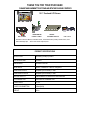
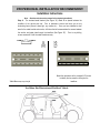
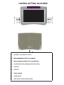
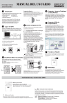
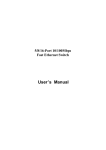
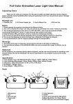
Thank You for purchasing the
SOS-102
10.2” FLIP-DOWN IN-CAR SYSTEM
USER MANUAL
V 1.5
Bravo View Technology
20153 Paseo Del Prado
Walnut, CA 91789
United States of America
909-869-0699
www.bravoview.com
THANK YOU FOR YOUR PURCHASE
PLEASE TAKE A MOMENT TO GET FAMILIAR WITH THE PACKAGE CONTENTS
10.2” Overhead LCD Screen
METAL
3 WIRE DOME
DIN CABLE
LIGHT CABLE
SUPPORT BRACE
IPOD CABLE
Not Shown- Instruction Manual, 10 Machine Screws, 15 Standard Screws (Pointed), Remote Control, and 2
Removable Hinge Caps.
*Note- not all screws maybe required
PRODUCT SPECIFICATIONS
RESOLUTION
800 RGB(H) X 480(V) PIXELS
LCD SCREEN SIZE
10.2 INCH
BRIGHTNESS
350 cd/m2 or 350 NIT
VIEW ANGLE
Top=65° / Bottom=65° Left=70° & Right=70°
AUDIO/VIDEO INPUT
Composite (RCA Female) ×1 sets
AUDIO/VIDEO OUTPUT
Composite (RCA Female) ×1 sets
IR AUDIO OUTPUT
2.3Mhz/2.8Mhz FOR WIRELESS HEADPHONES
FM TRANSMITTER
WIRELESS FM TRANSMITTER
POWER INPUT
DC 12V
POWER CONSUMPTION
16 Watt (MAX)
WEIGHT
3.81Lb
IMPORTANT INFORMATION
Before operating/installing your LCD Monitor, please read these instructions carefully.
1. Do not remove the Serial Number Label on this unit.
2. Do not use any chemical solvent, cleaning agent or corrosive detergent to
clean away dirt or fingerprints on the surface of the screen. Doing so
may cause irreversible damage to the surface of the LCD Screen. To
clean off dirt or fingerprints, it is recommended that a soft, damp lens
cleaning cloth be used while the unit is off.
3. Avoid installing the monitor screen in a position that is exposed to direct
sunlight and any air vents.
4. Install the unit in a dry location and avoid any area were build up of
condensation is possible. (Ex. Sunroof).
5. Avoid touching or pressing on the LCD screen.
6. Ensure that no foreign objects are in the unit when closing the LCD
screen.
7. If the unit overheats, or malfunctions, turn off the power. After the unit
has adequate time to cool down, turn it on again. If problem persist,
contact your dealer or Bravo View Technology.
8. Keep this manual for future references.
1. POWER: Power On/Off of DVD player and Display unit
2. EJECT: Eject the disc
3. Digits from 1 to 10 AND 10+: Select DVD section.
4. DVD/AUX: Select the Videos input ( DVD, AV input)
5. (↑
↑)
Bring up the current menu selections
6. (←
←)
Move Menu Choice to the left
7. ENTER: Start disc play and OSD function enter
8. (→
→)
9.(↓
↓)
Move Menu Choice to the right
Move Menu Choice Down or Select TV channels
10. SET UP: To access the DVD setup menu
11 Menu: Go to DVD main menu.
12.PLAY/PAUSE: Start disc play and pause
13.BACKWARD: X2/X4/X8/X20 SEARCH BACKWARD
14.FORWARD:X2/X4/X8/X20 SEARCH FORWARD
15.■
■ : STOPS Disc play
16.Previous(|<<): Press for preview chapter, track, and station
17.Next (>>|): Press for next chapter, track, and station
PROFESSIONAL INSTALLATION RECOMMENDED!
Installation Instructions
Note: Read the entire instruction manual before beginning installation!
Step A: The enclosed metal bracket (See Figure “A”) needs to be placed between the
headliner of the vehicle and roof. Prior to placement, ensure that there are not any
obstructing items (Sunroof, dome light, any screws etc.) Once you have identified a clear
area for the metal bracket and monitor, drill holes that will accommodate the screws between
the monitor and metal plate through the headliner (See Figure “B”).
Prior to any drilling,
ensure screws will fit into the metal bracket securely.
Front of Vehicle
*Metal Brace may vary in style
Match the metal brace to the overhead LCD screen
to identify the key areas for drilling into the
headliner.
See Below For Illustration of Profile of Vehicle
Step B (Wiring and Final installation)
REMOVE THE PLASTIC COVER OF HINGE BEFORE YOU INSTALL LCD MONITOR. With
the vehicle powered off, mount the monitor into place using the pre-drilled holes (Prior to
installation, always check the clearance of the screw lengths to ensure that you do not puncture
the roof).
With the Metal Bracket securely placed, drill small holes to accommodate the wiring cable so
that the Din cable, male end is at the area where the monitor will be installed. Ideally, the hole
for the cable should be drilled in the side areas of the mounting bracket. NOTE: The wires
are fed through both sides of the monitor. The other end of the cables should be run to the
area in which you will have your source unit installed (ex. DVD player).
BEFORE DRILLING ANY HOLES, ALIGN THE PLATE AND MONITOR TO ENSURE
PROPER PLACEMENT.
There are two sets of RCA cables (Yellow-Video Signal, White-Audio Left, Red-Audio Right).
This is for A/V Input and output. POWER- Connect the red wire to a fused source that shows +12volts
when the key is in the accessory position. Attach the black wire to any metal part of the vehicle that is
ground (-12volts).
Step C:
DOME LIGHT/MAP LIGHT INSTALLATION
Please note that your product includes the following 3-wire:
The color codes are:
Negative trigger: (MOST VEHICLES EXCEPT FORD)
Red Wire= Requires a “Constant” + 12 Volt connection*
Black Wire= Requires a -12 Volt (Ground)
White= -12 Volt Dome Light Trigger
* “Constant” means +12volt power regardless of the key position, or direct power from the battery.
Positive Trigger:
USUALLY MOST FORDS
Please note that a 12volt relay will be needed.
Please contact you professional installation center for
further details or contact our technical support.
This should complete the installation of the LCD Screen.
Pull the YELLOW latch on the left side of LCD monitor (see picture below) and
then swivel the screen down to your viewing angle. Note that the monitor only
locks in the 0° Angle (LCD facing roof).
! CAUTION !
Pulling down on the monitor
while locked, may result in
irreversible damage to the
SOS-102 and the interior roof.
Tuning the built in Wireless FM Module*
1.
2.
3.
4.
Turn on the Overhead LCD Screen and Source Unit.
Tune your FM radio to 87.7 (Or another station around this range.)
Play the source so that you can see the picture on the screen.
To pick another station, press the MENU button on the screen until you
navigate to the FM Transmitter option.
5. Using the UP AND DOWN buttons, scroll to the desired station you wish
to use for the transmition of the audio. The default setting is 87.7 MHz.
(Pick a radio station that normally does not receive a signal in your
geographical area)
6. Tune your car stereo to the newly set station to test.
*This unit is designed to work in North America
CONTROL BUTTONS ON SCREEN
1
2
3
4
5
6
7
8
9
1.
MAIN MENU OPTION/SELECT OPTION
2.
MENU NAVIGATION UP BUTTON / VOLUME UP
3.
MENU NAVIGATION DOWN BUTTON / VOLUME DOWN
4.
SOURCE-SWITCH DVD MODE AND VIDEO INPUT (IPOD)
5.
DVD EJECT
6.
DVD STOP
7.
DVD PLAY/PAUSE
8.
POWER ON/OFF
9.
DOME LIGHT CONTROL (ON/OFF/DOOR)
Limited Warranty
Bravo View Technology warrants this product (including any accessory and/or cable) against
defects in material or workmanship as follows:
1.
Labor. For a period of 1 Year from original date of purchase, if the product is determined to
be defective, Bravo View will repair or replace the product at no charge.
2.
Parts. For a period of 1 Year from original date of purchase, Bravo View will at no charge,
replace with new or rebuilt parts in exchange for defective parts.
The warranty will either
continue from date of original purchase or 90 days from repair (whichever is longer).
This warranty does not cover customer misuse, improper installation, poor signal (including any
“noise”), cosmetic damage, damage due by accident, abuse, negligence, commercial use,
and improper operation.
Proof of Purchase in the form of a copy of bill of sale or copy of receipt/invoice, which shows
clearly the sale of the unit, is required.
Repair or Replacement as provided under this warranty is the exclusive remedy of the consumer.
Bravo View Technology shall not be liable for any incidental or consequential damage for
breach of any express or implied warranty on this product.
In no event shall Bravo View
Technology be liable for any incidental or consequential damage whatsoever arising out of the
use or inability to use the product.
Under no circumstance shall Bravo View Technology’s
liability exceed the purchase price paid for the product.
Except to the extent prohibited by
applicable law, any implied warranty or merchantability or fitness for a particular purpose on
this product is limited in duration to the duration of this warranty.
PROCESS:
1.
Contact Bravo View and describe the problem with the unit. Please have your model
number, date of purchase and where it was purchased ready.
If requesting on-line,
please include your name, address and telephone number.
2.
If determined that the item is warrantable, Bravo View will issue a RA# and provide an
address to mail the unit back to.
3.
Bravo View is not responsible for articles lost or stolen during shipping. IT IS ADVISABLE
TO SHIP THE UNIT IN A METHOD IN WHICH YOU CAN TRACK THE PACKAGE, AND POSSIBLY
INSURE THE PACKAGE. Bravo View does not cover the expense of mailing the unit back
to us.
4.
Once Bravo View receives and validates the unit to ensure it is within warranty, Bravo
View will replace the unit, fix the unit, or offer a substitute of the unit if a replacement is
not available. Bravo View may send a refurbished unit back.
5.
Bravo View will mail the unit back to you.
To obtain warranty service, you must contact Bravo View Technology for a Return Authorization
Number (RA#). 866-40-BRAVO or visit www.bravoview.com.