1
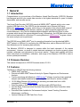
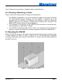
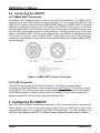
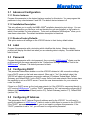
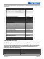
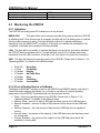
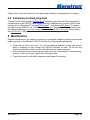
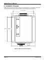
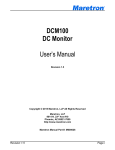
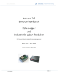
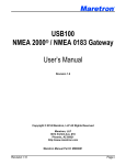
VDR100 Vessel Data Recorder User’s Manual Revision 1.2 Copyright © 2013 Maretron, LLP All Rights Reserved Maretron, LLP 9014 N. 23rd Ave #10 Phoenix, AZ 85021 http://www.maretron.com Maretron Manual Part #: M003025 Revision 1.2 Page i VDR100 User’s Manual Revision History Revision Description 1.0 Original document 1.1 Added information on USB flash drive shipped with product 1.2 Firmware Release 3.0.2.9 Added information on LAN connections Added information on USB LED Flash Codes Page ii Revision 1.2 Table of Contents 1 General ................................................................................................................................1 1.1 Introduction ....................................................................................................................1 1.2 Firmware Revision .........................................................................................................1 1.3 Features ........................................................................................................................1 1.4 VDR100 Accessories .....................................................................................................2 1.5 Quick Install ...................................................................................................................2 1.6 Theory of Operation .......................................................................................................2 1.6.1 General Concepts ...............................................................................................2 1.6.2 Operating States .................................................................................................3 1.6.3 TCP/IP Networks ................................................................................................4 1.7 Data Analysis .................................................................................................................6 2 Installation ............................................................................................................................6 2.1 Unpacking the Box .........................................................................................................6 2.2 Choosing a Mounting Location ......................................................................................7 2.3 Mounting the VDR100 ...................................................................................................7 2.4 Connecting the VDR100 ................................................................................................8 2.4.1 NMEA 2000® Connection ....................................................................................8 2.4.2 LAN Connection ..................................................................................................8 3 Configuring the VDR100 ......................................................................................................8 3.1 Advanced Configuration ................................................................................................9 3.1.1 Device Instance ..................................................................................................9 3.1.2 Installation Description ........................................................................................9 3.1.3 Restore Factory Defaults ....................................................................................9 3.2 Label ..............................................................................................................................9 3.3 Password .......................................................................................................................9 3.4 Configuring DHCP .........................................................................................................9 3.5 Configuring IP Address ..................................................................................................9 3.6 Configuring Subnet Mask ............................................................................................ 10 3.7 Configuring Default Gateway ....................................................................................... 10 3.8 Configuring Default DNS ............................................................................................. 10 4 Usage ................................................................................................................................. 10 4.1 Recording Data ............................................................................................................ 10 4.2 USB Flash Drive Selection........................................................................................... 10 4.2.1 USB Flash Drives .............................................................................................. 10 4.2.2 USB Flash Drive Size........................................................................................ 11 4.3 Monitoring the VDR100 ............................................................................................... 12 4.3.1 Indicators .......................................................................................................... 12 4.3.2 From a Display Device or Software ................................................................... 12 5 Maintenance....................................................................................................................... 13 6 Troubleshooting ................................................................................................................. 14 7 Technical Specifications ..................................................................................................... 15 8 Technical Support .............................................................................................................. 17 9 Installation Template .......................................................................................................... 18 10 Maretron (2 Year) Limited Warranty ................................................................................... 19 Revision 1.2 Page iii VDR100 User’s Manual Table of Figures Figure 1 – Mounting the VDR100 .............................................................................................. 7 Figure 2 – NMEA 2000® Connector Face Views ....................................................................... 8 Figure 3 – Troubleshooting Guide ........................................................................................... 14 Figure 4 – Mounting Surface Template ................................................................................... 18 Page iv Revision 1.2 1 General 1.1 Introduction Congratulations on your purchase of the Maretron Vessel Data Recorder (VDR100). Maretron has designed and built your vessel data recorder to the highest standards for years of reliable, dependable, and accurate service. The Vessel Data Recorder (VDR100) records all NMEA 2000® network activity onto a usersupplied USB flash drive. The VDR100 can be accessed over a Ethernet LAN using Maretron’s N2KExtractor® program, which lets you view graphs of the collected data, maps of the course traveled during data collection, and lets you export selected parameters into comma delimited (.CSV) files for detailed statistical analysis with Microsoft Excel or other programs which accept the comma-delimited format. Alternatively, the USB flash drive can be removed and inserted into a Windows PC running Maretron’s N2KExtractor® program, where the same analysis can be performed. The VDR100 has an NMEA 2000® port for recording information from the attached NMEA 2000® network, a USB port for connecting the USB flash drive, and an Ethernet LAN (Local Area Network) port for accessing data remotely. The Maretron VDR100 is designed to operate within the harsh demands of the marine environment. However, no piece of marine electronic equipment can function properly unless installed, calibrated, and maintained in the correct manner. Please read carefully and follow these instructions for installation, calibration, and usage of the Maretron VDR100 in order to ensure optimal performance. 1.2 Firmware Revision This manual corresponds to VDR100 firmware revision 3.0.2.9. 1.3 Features The Maretron VDR100 has the following features: NMEA 2000® interface Records all NMEA 2000® Network Activity for System Diagnosis and Performance Analysis Can be used along with Maretron’s N2KExtractor® software to perform basic graphical analysis and detailed statistical analysis using Microsoft Excel or similar software 10/100 Mbps Ethernet LAN interface for accessing recorded data from a LANconnected PC running N2KExtractor® Data Recorded on Solid State Memory via Removable USB Flash Drive Circular Buffer Preserves Latest Recorded Data while Oldest Data Overwritten when Memory is Full Recorded Data Available for Performance Analysis, Vessel Tracking, Preventive Maintenance, and More Optional Waterproof USB Flash Drive Cover Revision 1.2 Page 1 VDR100 User’s Manual Free Data Extraction Software (N2KExtractor®) allows you to view voyages on a map, perform graphing of up to four parameters, and builds Comma Delimited Files for detailed data analysis using Microsoft Excel or other spreadsheet software. 1.4 VDR100 Accessories Maretron offers the following accessories for the VDR100: PX0852 USB Waterproof Cover M003029 Corsair Voyager GT 16GB USB Flash Drive PX0837/5M00 Waterproof Ethernet Cable 16.4' 1.5 Quick Install Installing the Maretron VDR100 involves the following steps. Please refer to the individual sections for additional details. 1. 2. 3. 4. 5. Unpacking the Box (Section 2.1) Choosing a Mounting Location (Section 2.2) Mounting the VDR100 (Section 2.3) Connecting the VDR100 (Section 2.4) Configuring the VDR100 (Section 3) 1.6 Theory of Operation The VDR100 records every frame of NMEA 2000® network activity onto the attached USB flash drive. 1.6.1 General Concepts 1.6.1.1 Data Recording The VDR100 records every single frame of data on the NMEA 2000® network. In order to perform performance analysis, the time at which each event occurs must be accurately recorded. To this end, there must be a source of time information on the NMEA 2000® network, for example, a Maretron GPS or equivalent. WARNING At least one device transmitting valid data in the NMEA 2000® System Time (126992) message, for example, a GPS receiver, must be operating on the network in order for the VDR100 and the N2KExtractor® program to be able to correlate the data with the time when it was present on the network. The VDR100 records data to a circular buffer on the USB flash drive. When the USB flash drive becomes near full, the oldest data on the device is deleted in order to make room for newer data. Page 2 Revision 1.2 You may monitor the available space on a USB flash drive using N2KView® software or a Maretron DSM150/DSM250 display. If you wish to keep all recorded data on the USB flash drive, simply remove the USB flash drive from the VDR100 and replace it with an empty USB flash drive before the first USB flash drive becomes full. 1.6.1.2 Flash File System The USB flash drive will be re-formatted the first time it is used in the VDR100. This is done in order to ensure filesystem integrity of the USB flash drive in the cases of removal of the device from the VDR100 and also in cases of power removal from the VDR100, WARNING When you plug a new USB flash drive (one which has never been used before in a VDR100) into the VDR100, ALL DATA ON THE MEMORY DRIVE WILL BE DESTROYED. If your USB flash drive has data you wish to save, please archive it before plugging the USB flash drive into the VDR100. The filesystem that is created on the USB flash drive is not compatible with Microsoft Windows. Drivers for the filesystem used by the VDR100 are included with the Maretron N2KExtractor® software. 1.6.2 Operating States The VDR100 has several different operating states, which can be monitored by observing the USB LED on the unit, or by monitoring the VDR Status message transmitted by the VDR100 using a DSM150, DSM250, or N2KView® software. Recording – the VDR100 is recording data Formatting – the VDR100 is formatting the USB flash drive for use, and will begin recording when complete Erasing – the VDR100 is erasing old files from the USB flash drive, and will begin recording when complete No Flash Drive – no USB flash drive is present; insert a USB flash drive into the VDR100 Error – the VDR100 has detected an error on USB flash drive; check the USB flash drive Initializing – the VDR100 is initializing the USB flash drive, and will begin recording when complete Incompatible – the VDR100 has detected an incompatible USB flash drive which contains VDR100 upgrade software; either remove and erase the USB flash drive or replace it with a different USB flash drive for recording data Revision 1.2 Page 3 VDR100 User’s Manual 1.6.3 TCP/IP Networks The networking protocol that is used for the communication between the PC running N2KExtractor® software and the VDR100 is the TCP/IP protocol. This protocol is used by the World Wide Web, FTP (File Transfer Protocol), and many others of the most popular applications on the Internet. The TCP/IP connection can be made over an Ethernet connection, a Wi-Fi connection, cellular phone data connection, and many other types of media. In fact, a single packet of TCP/IP data may traverse multiple types of media on its journey. The TCP/IP protocol is supported by most operating systems, as well as Internetconnected cellular phones. Each computer on a TCP/IP network is identified by an IP address unique to that network. An IP address consists of four numbers, each ranging between 0 and 255, separated by periods. This is referred to a dotted decimal notation. Examples of IP addresses in this format are 10.0.0.1, and 62.12.31.188. The IP address may either be hard coded into the computer (this means that the address is static which makes the computer easier to find) or assigned at each startup by a DHCP (Dynamic Host Control Protocol) server, typically found as part of a router. The router can be configured to reserve a specific address for the computer and then assign that same address each time at startup. If the router chooses a different address each time, then the computer may be difficult to find on the network. This is not a problem for a client such as N2KExtractor®, but servers such as the VDR100 should be at a known address. 1.6.3.1 NAT (Network Address Translation) If you wish to use N2KExtractor® to view data from a VDR100 on a WAN through an Internet connection, please read this section. If your N2KExtractor® computer and the VDR100 are on the same LAN, you may skip this section. In the early days of the Internet, each computer connected to the Internet had its own IP address. With the explosive growth of the Internet, the number of distinct IP addresses is starting to run out. It is no longer practical for an Internet Service Provider (ISP) to provide its customers with individual IP addresses for each component the customer wishes to connect to the Internet. Rather, the ISP normally assigns each customer a single IP address, and a router implementing Network Address Translation (NAT) is connected to the Internet connection (sometimes referred to as the Wide Area Network, or WAN, connection) on one side, and to the Local Area Network, or LAN, on the other side. Each computer on the LAN side of the connection will be assigned its own IP address, typically in the ranges 192.168.x.x, 10.x.x.x, and 172.16.x.x through 172.31.x.x, where x can be any number in the range 0-255. The WAN connection will be assigned a single IP address by the ISP. Generally, network address translation is performed by a router that is connected to the Internet via a Cable or DSL connection on the WAN side, and to the local area network (LAN) via Ethernet or Wi-Fi connections. In order to access a VDR100 on the local area network from an N2KExtractor® outside of the LAN, you must configure the router to allow incoming connections on port 6544 and to forward these connections to the IP address of the VDR100. Consult the documentation that came with your router for details. Page 4 Revision 1.2 1.6.3.2 PAT (Port Address Translation) If you wish to use N2KExtractor® to view data from a VDR100 on a WAN through an Internet connection and your Internet Service Provider does not allow communication on port 6544, please read this section. If your N2KExtractor® computer and VDR100 are on the same LAN, or your ISP allows communication over port 6544, you may skip this section. The VDR100 requires a connection to be made on port 6544. Routers that support Port Address Translation can be set up to accept incoming connections on a different port and to forward these connections to port 6544 on the IP address of the VDR100. This change in the port address is known as the ability to do Port Address Translation as well as Network Address Translation. Not all routers have this ability; please consult the documentation that came with your router for details. N2KExtractor® must then be set up to request a connection to the WAN IP Address of the router and the new port number. 1.6.3.3 Static and Dynamic IP Addressing If you wish to use N2KExtractor® to view data from a VDR100 on a WAN through an Internet connection, please read this section. If your VDR100 and your N2KExtractor® computer are on the same LAN, you may skip this section. If you request a Static IP Address from your ISP when you set up your Internet connection, the WAN IP address will always be the same. If you didn’t make this request, your ISP will assign you a Dynamic IP Address, which may actually change from time to time. In this way, the ISP only needs to have enough addresses to cover its customers who are connected to the Internet at any given time. If you stop or lose your Internet connection, your Dynamic IP address will be released and may be reassigned to someone else. If you wish to connect to a VDR100 from outside your vessel’s LAN via an Internet connection, you have two choices. First, you can request a static IP address from the ISP for your vessel; secondly, you may register your VDR100’s IP address with a “dynamic DNS service”, such as the ones offered freely by www.dyndns.org, among others. Please visit their websites for more information on how dynamic DNS services operate. 1.6.3.4 Data Security and Encryption Making your vessel’s data available over a LAN or WAN presents multiple security concerns. First, it is desirable to keep anyone from viewing your vessel’s data without authorization. Second, and more important, it is imperative that no unauthorized persons be able to place data onto your vessel’s NMEA 2000® network. The VDR100 protects your vessel’s data with multiple levels of protection. First, any data that passes between the VDR100 and any N2KExtractor® station components is protected using industry-standard SSL encryption. This encryption standard is widely used to protect financial information on the internet. Each communication session negotiates a random encryption key every time a connection is established. This makes the data secure over public and private Wi-Fi networks, as well as the internet. Revision 1.2 Page 5 VDR100 User’s Manual Second, each N2KExtractor® station that wishes to connect to a VDR100 must authenticate itself by means of a password. The password is transmitted by the N2KExtractor® station to the VDR100 over the encrypted communication link. The VDR100 compares the password to the one it was programmed with. Only if the password received from the station matches the VDR100’s stored password is the station granted access to the NMEA 2000® network data. 1.7 Data Analysis In order to retrieve data from the VDR100, either 1) access the VDR100 over a LAN from a Windows PC on which N2KExtractor® software has been installed, or 2) remove the USB flash drive from the VDR100 and plug into a Windows PC on which N2KExtractor® software has been installed. Please refer to the N2KExtractor® User’s Manual for details. WARNING Do not plug a USB flash drive that has been used in a VDR100 into a Windows PC without first installing the Maretron N2KExtractor® software. Failure to install the N2KExtractor® software before plugging in the USB flash drive may result in the data on the flash memory device being destroyed. WARNING If a USB flash drive that has been used in the VDR100 is plugged into a Windows PC that has not had the N2KExtractor® software installed, then Windows will not recognize the format of the USB flash drive and will ask you to format it. DO NOT FORMAT THE USB FLASH drive, as this WILL result in all of the data on the USB flash memory drive being destroyed. 2 Installation 2.1 Unpacking the Box When unpacking the box containing the Maretron VDR100, you should find the following items: 1 – VDR100 Vessel Data Recorder 1 – Parts Bag containing 4 Stainless Steel Mounting Screws 1 – VDR100 User’s Manual 1 – Warranty Registration Card 1 – USB Flash Drive (preformatted for the VDR100) Page 6 Revision 1.2 If any of these items are missing or damaged, please contact Maretron. 2.2 Choosing a Mounting Location Please consider the following when choosing a mounting location. 1. The VDR100 is waterproof, so it can be mounted in a damp or dry location. Note that the USB Waterproof Cover accessory must be installed to waterproof all of the connections to the VDR100. If the Ethernet LAN Interface is used, the Waterproof Ethernet Cable must be installed to waterproof the Ethernet LAN connection. The NMEA 2000® network interface is already waterproof. 2. The orientation is not important, so the VDR100 can be mounted on a horizontal deck, vertical bulkhead, or upside down if desired. 3. The VDR100 is temperature-rated to 55°C (130°F), so it should be mounted away from engines or engine rooms where the operating temperature exceeds the specified limit. 2.3 Mounting the VDR100 Attach the VDR100 securely to the vessel using the included stainless steel mounting screws or other fasteners as shown in Figure 1 below. Do not use threadlocking compounds containing methacrylate ester, such as Loctite Red (271), as they will cause stress cracking of the plastic enclosure. Figure 1 – Mounting the VDR100 Revision 1.2 Page 7 VDR100 User’s Manual 2.4 Connecting the VDR100 2.4.1 NMEA 2000® Connection The NMEA 2000® connector can be found on the side of the enclosure. The NMEA 2000 ® connector is a round five pin male connector (see Figure 2). You connect the VDR100 to an NMEA 2000® network using a Maretron NMEA 2000® cable (or an NMEA 2000® compatible cable) by connecting the female end of the cable to the VDR100 (note the key on the male connector and keyway on the female connector). Be sure the cable is connected securely and that the collar on the cable connector is tightened firmly. Connect the other end of the cable (male) to the NMEA 2000® network in the same manner. The VDR100 is designed such that you can plug or unplug it from an NMEA 2000® network while the power to the network is connected or disconnected. Please follow recommended practices for installing NMEA 2000 ® network products. Figure 2 – NMEA 2000® Connector Face Views 2.4.2 LAN Connection The VDR100 has one external RJ-45 LAN connector. The RJ-45 connector enables connection to an external network, which is necessary for N2KExtractor® to be able to connect to the VDR100. The LAN connector can be made waterproof with the purchase of the optional PX837/5M00 Waterproof Ethernet Cable, which has a waterproof cover which engages the threads on the RJ-45 LAN connector, creating a waterproof seal. 3 Configuring the VDR100 The VDR100 has several configurable parameters, which are shown below including the default values. If you are not using the default values, then you will need to refer to the corresponding section for configuring the VDR100 appropriately. You may configure the VDR100 using a Maretron DSM150 or DSM250 display or Maretron N2KAnalyzer® software. Page 8 Revision 1.2 3.1 Advanced Configuration 3.1.1 Device Instance Program this parameter to the desired instance number for this device. You can program this parameter to any value between 0 and 252. The default device instance is 0 3.1.2 Installation Description This entry allows you to modify the NMEA 2000® installation description text strings. You can enter any information you like here, such as the date the unit was installed, or the location in which it was installed, for later reference. Tools such as Maretron N2KAnalyzer ® allow you to view these values later. The default installation description is blank text. 3.1.3 Restore Factory Defaults This option restores all settings on the VDR100 device to their factory default states. 3.2 Label Program this parameter with a text string which identifies this device. Maretron display products will display this label text when you are selecting data to display. The default device label is blank. 3.3 Password Program this parameter with a text password. Any connecting N2KExtractor® clients must be programmed with the same password in the “Connections Settings->Password” field in the N2KExtractor® software. The default password is blank. 3.4 Configuring DHCP This parameter determines whether or not the VDR100 obtains its LAN connection settings from a DHCP server on the local area network. When set to “Yes” (the default value), the VDR100 will obtain all necessary connection settings (IP Address, Subnet Mask, Default Gateway, and Default DNS) from a DHCP server on the local area network. Most routers have the capability to act as a DHCP server. Consult the user documentation for your network’s router for details. If there is no DHCP server on the local area network (or if the VDR100 is connected directly to a PC running N2KExtractor®), set the “DHCP” parameter to “No” and manually configure the IP Address (section 3.5), Subnet Mask (section 3.6), Default Gateway (section 3.7), Default DNS (section 3.8). 3.5 Configuring IP Address This parameter is the IP (Internet Protocol) address used by the VDR100. You will need to specify this address to N2KExtractor® clients in order to allow them to connect to the VDR100. If the “DHCP” parameter is set to “Yes”, you do not need to configure this parameter. If the “DHCP” parameter is set to “No”, you will need to configure this parameter. Revision 1.2 Page 9 VDR100 User’s Manual 3.6 Configuring Subnet Mask This is a mask used to divide an IP Address into subnets. Basically, it tells the computer how much of the IP Address defines the network, and how much may be used by computers on the network. For most networks, the first three parts of the IP address define the network (i.e., every computer on the network must have the same values), and the last part defines the computer (i.e., every computer on the network must have a different value). Where the value 255 appears in the subnet mask, the values define the network and must be the same. The most common value is 255.255.255.0. If the “DHCP” parameter is set to “Yes”, you do not need to configure this parameter. If the “DHCP” parameter is set to “No”, you will need to configure this parameter. 3.7 Configuring Default Gateway This is the IP address of the router. If the “DHCP” parameter is set to “Yes”, you do not need to configure this parameter. If the “DHCP” parameter is set to “No”, you will need to configure this parameter. 3.8 Configuring Default DNS This is the IP address of a computer on the Internet that can identify and locate computer systems and resources on the internet. In most cases, this should not be required by the VDR100 and may be left blank. If the “DHCP” parameter is set to “No”, you will need to configure this parameter. 4 Usage 4.1 Recording Data To record data, plug a USB flash drive into the Type A USB connector on the VDR100. A waterproof cover accessory is available that will allow the USB port to be made waterproof with a USB flash drive installed, although this cover will not fit all USB flash drives, so please check the dimensions of the USB flash drive to be sure that the waterproof cover accessory will fit over the drive. 4.2 USB Flash Drive Selection 4.2.1 USB Flash Drives WARNING Because of the methods that the VDR100 records every frame of network data for quick retrieval and analysis, the VDR100 must only be used with a high performance USB flash drive from the list of supported USB flash drives. Page 10 Revision 1.2 The VDR100 is supported ONLY with the following list of USB flash drives (more will be added in the future): USB Flash Drive Model Corsair Flash Survivor USB 3.0 32GB Corsair Flash Survivor Stealth USB 3.0 32GB Corsair Flash Survivor USB 3.0 64GB Corsair Flash Survivor Stealth USB 3.0 64GB Corsair Flash Voyager GT USB 3.0 Hama “Probo” FlashPen, USB 3.0 Kingston DataTraveler Elite 3.0 Kingston DataTraveler HyperX 3.0 Kingston DataTraveler R3.0 Kingston DataTraveler Ultimate 3.0 Generation 2 LaCie FastKey USB 3.0 Lexar JumpDrive Triton Mushkin Ventura Pro Patriot Supersonic Patriot Supersonic Rage XT Patriot Supersonic Boost XT Patriot Supersonic Magnum Sandisk Extreme USB 3.0 Sony Micro Vault Mach SuperTalent SuperCrypt SuperTalent Express RC-8 SuperTalent Express Ram Cache Capacities (GB) 32 32 64 64 16,32,64 8, 16, 32 16, 32, 64 64, 128, 256 16,32,64 16, 32, 64 30, 60, 120 16,32,64 32,64 64 32,64 8,16,32,64 64, 128 16,32,64 8,16,32,64 16,32,64,128,256 25,50,100 16,32,64 SuperTalent Express ST4 SuperTalent RAIDDrive 16,32,64 32,64,128 SuperTalent DataGuardian USB 3.0 Transcend JetFlash 780 8,16,32 16 4.2.2 USB Flash Drive Size The VDR100 uses a circular buffer, which means that if the USB flash drive becomes full, then the oldest data will be erased to make room for new data. Depending on how much data you wish to record without overwriting older data, the following table can be used to determine the capacity of the USB Flash Drive you need. These figures are estimated assuming a 25% loaded system (approx 463 frames/second). Recording Period 1 second 1 minute 1 hour 1 day Revision 1.2 Media Storage Capacity 7862 bytes 471,750 bytes 29 MBytes 680 MBytes Page 11 VDR100 User’s Manual 1 week 1 month (30 days) 1 year (365.25 days) 5 GBytes 21 GBytes 248 GBytes 4.3 Monitoring the VDR100 4.3.1 Indicators The VDR100 has three green LED indicators on its top surface: NMEA 2000: This light will be red for several seconds after powerup while the VDR100 is initializing itself. Once this process is complete, this light will be lit a steady green to indicate that the main processor is active. The light will blink on and off to indicate data being transferred over the NMEA 2000® connection. If this light is lit red after the initialization has completed, it indicates that a problem has been detected. LAN: This light will be on steadily to indicate that there is an active link connection between the VDR100 and the attached device. The light will blink on and off to indicate data being transferred over the LAN connection. If the light is off, then there is no active link connection. USB: This light will indicate the operating state of the VDR100. Please refer to Section 1.6.2, “Operating States”, for details of the different states. Solid ON 1 Flash 2 Flashes 3 Flashes 4 Flashes 5 Flashes 6 Flashes Recording Formatting Erasing No Flash Drive Error Initializing Incompatible 4.3.2 From a Display Device or Software The Maretron N2KView® software as well as the DSM150 and DSM250 display units have a Vessel Recorder category that allows you to monitor or set alerts on various operating parameters of the VDR100. Parameters that can be monitored include: State – this is the operating state of the VDR100. Please refer to Section 1.6.2, “Operating States”, for details of the different states. Memory Used – amount of data (in GB) that has been used on the USB flash drive Memory Available – amount of data (in GB) that can still be stored on the USB flash drive Memory Capacity – the total amount of data that the USB flash drive is capable of storing. Percent Used – the percent of the capacity of the USB flash drive that has been used for storing data Percent Available – the percent of the capacity of the USB flash drive that is still available for storing data Page 12 Revision 1.2 Please refer to the user’s manual for the appropriate software or display product for details. 4.4 Extracting and Analyzing Data You can use the freely available N2KExtractor® program to plot data over the time interval of recorded data on the VDR100, either by removing the USB flash drive from the VDR100 and inserting it into a Windows PC running N2KExtractor®, or by using N2KExtractor® to retrieve the data from the VDR100 over a LAN. The N2KExtractor® program can be downloaded from the following web page: http://www.maretron.com/products/N2KExtractor.php. Please refer to the N2KExtractor® User’s Manual, available on the same web page, for details. 5 Maintenance Regular maintenance is not required; however, an occasional inspection will ensure continued proper operation of the Maretron VDR100. Perform the following tasks periodically: Clean the unit with a soft cloth. Do not use chemical cleaners as they may remove paint or markings or may corrode the VDR100 enclosure or seals. Do not use any cleaners containing acetone, as they will deteriorate the plastic enclosure. Ensure that the unit is mounted securely and cannot be moved relative to the mounting surface. If the unit is loose, tighten the mounting screws. Check the security of all cable connections and tighten if necessary. Revision 1.2 Page 13 VDR100 User’s Manual 6 Troubleshooting If you notice unexpected operation of the Maretron VDR100, follow the troubleshooting procedures in this section to remedy simple problems. Symptom USB indicator not lit NMEA 2000® indicator not lit LAN indicator not lit Troubleshooting Procedure 1. Ensure that the USB flash drive is properly plugged into the USB connector 1. Ensure that power is supplied to the NMEA 2000® indicator via the NMEA 2000® cable, and that the NMEA 2000® connection is secure. 1. Ensure that the network cable is connected both to the VDR100 and to a switch or router or another network device. 2. Ensure that the device on the other end of the network cable is powered. VDR100 reports 1. Ensure that the USB flash drive is properly plugged into the USB an “Error” state connector 2. Try using a different USB flash drive 3. Cycle the power to the VDR100 VDR100 reports 1. Ensure that the USB flash drive is properly plugged into the USB a “No Flash connector Drive” state 2. Try using a different USB flash drive VDR100 reports 1. The VDR100 will not record on a USB flash drive which contains a “Incompatible VDR100 upgrade software. If this USB flash drive is on the supported Flash Drive” list in Section 4.2.1, “USB Flash Drives”, simply use a Windows state computer to erase the “VDR100_RCV” directory from the USB flash drive and reinstall the USB flash drive into the VDR100. ® N2KExtractor 1. If you have programmed the VDR100 to use DHCP, ensure that there Clients cannot is an active DHCP server on your LAN. successfully 2. Ensure that the NMEA 2000® connection is secure, and that the NMEA connect to the 2000® network is powered. VDR100 3. Ensure that you have entered the correct Serial Number or IP Address of the VDR100 into N2KExtractor®. 4. Ensure that the LAN LED on the VDR100 is lit, indicating an active link connection to the LAN. If it is not lit, check the Ethernet connection and make sure that the router or device to which the VDR100 is connected is powered on. 5. Ensure that the Password entered into N2KExtractor® under the “Connections Settings” window matches the password that has been programmed into the VDR100. Figure 3 – Troubleshooting Guide If these steps do not solve your problem, please contact Maretron Technical Support (refer to Section 8 for contact information). Page 14 Revision 1.2 7 Technical Specifications Specifications Parameter ® NMEA 2000 Connector ® NMEA 2000 Isolation USB Standard USB Connector Value DeviceNet Micro-C Opto-Isolated USB 1.1 USB Type A USB Supported Signals USB Auxiliary Power USB Baud Rate Ethernet Interface Ethernet Connector D+, D-, +5V, GND +5 Volts < 200 mA Up to 12 Mb/s 100 Mb/s RJ-45 Comment Industry Standard Waterproof No Electrical Connection Across Bridge Industry Standard Waterproof, for Connection of USB Flash Memory Device for Recording Data Full Speed USB Data Rate ® For connection via N2KExtractor Industry Standard Waterproof Certifications Parameter ® NMEA 2000 Standard Maritime Navigation and Radiocommunication Equipment & Systems Maritime Navigation and Radiocommunication Equipment & Systems FCC and CE Mark Comment Level A IEC 61162-3 IEC 60945 Electromagnetic Compatibility NMEA 2000® Parameter Group Numbers (PGNs) Description Response to Requested PGNs Protocol PGNs Periodic PGNs PGN # 126464 126996 126998 059392 059904 060416 060160 060928 065240 126208 130833 PGNs Recorded All PGN Name PGN List (Transmit and Receive) Product Information Configuration Information ISO Acknowledge ISO Request ISO Transport Protocol, Connection Management ISO Transport Protocol, Data Transfer ISO Address Claim ISO Address Command NMEA Request/Command/Acknowledge Vessel Data Recorder Status (Maretron Proprietary) All Default Rate N/A N/A N/A N/A N/A N/A N/A N/A N/A N/A 10 seconds N/A Electrical Parameter Operating Voltage Power Consumption Load Equivalence Number (LEN) Reverse Battery Protection Load Dump Protection Value 9 to 32 Volts <200mA 4 Yes Yes Comment DC Voltage Average Current Drain ® NMEA 2000 Spec. (1LEN = 50 mA) Indefinitely Energy Rated per SAE J1113 Mechanical Parameter Size Weight Revision 1.2 Value Comment 5.000” x 4.500” x 2.375” Including Flanges for Mounting 127mm x 114mm x 60 mm) 12 oz. (340 g) Page 15 VDR100 User’s Manual Environmental Parameter IEC 60945 Classification Degree of Protection Operating Temperature Storage Temperature Relative Humidity Vibration Rain and Spray Solar Radiation Corrosion (Salt Mist) Electromagnetic Immunity Safety Precautions Page 16 Value Exposed IP67 -25°C to 55°C -40°C to 70°C 93%RH @40° per IEC60945-8.2 2 2-13.2Hz @ ±1mm, 13.2-100Hz @ 7m/s per IEC 60945-8.7 12.5mm Nozzle @ 100liters/min from 3m for 30min per IEC 60945-8.8 Ultraviolet B, A, Visible, and Infrared per IEC 60945-8.10 4 times 7days @ 40°C, 95%RH after 2 hour Salt Spray Per IEC 60945-8.12 Conducted, Radiated, Supply, and ESD per IEC 60945-10 Dangerous Voltage, Electromagnetic Radio Frequency per IEC 60945-12 Revision 1.2 8 Technical Support If you require technical support for Maretron products, you can reach us in any of the following ways: Telephone: 1-866-550-9100 Fax: 1-602-861-1777 E-mail: [email protected] World Wide Web: http://www.maretron.com Mail: Maretron, LLP Attn: Technical Support 9014 N. 23rd Ave Suite 10 Phoenix, AZ 85021 USA Revision 1.2 Page 17 VDR100 User’s Manual 9 Installation Template Please check the dimensions before using the following diagram as a template for drilling the mounting holes because the printing process may have distorted the dimensions. 3.9” (99.1mm) 4.5” (114.3mm) Figure 4 – Mounting Surface Template Page 18 Revision 1.2 10 Maretron (2 Year) Limited Warranty Maretron warrants the VDR100 to be free from defects in materials and workmanship for two (2) years from the date of original purchase. If within the applicable period any such products shall be proved to Maretron’s satisfaction to fail to meet the above limited warranty, such products shall be repaired or replaced at Maretron’s option. Purchaser's exclusive remedy and Maretron’s sole obligation hereunder, provided product is returned pursuant to the return requirements below, shall be limited to the repair or replacement, at Maretron’s option, of any product not meeting the above limited warranty and which is returned to Maretron; or if Maretron is unable to deliver a replacement that is free from defects in materials or workmanship, Purchaser’s payment for such product will be refunded. Maretron assumes no liability whatsoever for expenses of removing any defective product or part or for installing the repaired product or part or a replacement therefore or for any loss or damage to equipment in connection with which Maretron’s products or parts shall be used. With respect to products not manufactured by Maretron, Maretron’s warranty obligation shall in all respects conform to and be limited to the warranty actually extended to Maretron by its supplier. The foregoing warranties shall not apply with respect to products subjected to negligence, misuse, misapplication, accident, damages by circumstances beyond Maretron’s control, to improper installation, operation, maintenance, or storage, or to other than normal use or service. THE FOREGOING WARRANTIES ARE EXPRESSLY IN LIEU OF AND EXCLUDES ALL OTHER EXPRESS OR IMPLIED WARRANTIES, INCLUDING BUT NOT LIMITED TO THE IMPLIED WARRANTIES OF MERCHANTABILITY AND OF FITNESS FOR A PARTICULAR PURPOSE. Statements made by any person, including representatives of Maretron, which are inconsistent or in conflict with the terms of this Limited Warranty, shall not be binding upon Maretron unless reduced to writing and approved by an officer of Maretron. IN NO CASE WILL MARETRON BE LIABLE FOR INCIDENTAL OR CONSEQUENTIAL DAMAGES, DAMAGES FOR LOSS OF USE, LOSS OF ANTICIPATED PROFITS OR SAVINGS, OR ANY OTHER LOSS INCURRED BECAUSE OF INTERRUPTION OF SERVICE. IN NO EVENT SHALL MARETRON’S AGGREGATE LIABILITY EXCEED THE PURCHASE PRICE OF THE PRODUCT(S) INVOLVED. MARETRON SHALL NOT BE SUBJECT TO ANY OTHER OBLIGATIONS OR LIABILITIES, WHETHER ARISING OUT OF BREACH OF CONTRACT OR WARRANTY, TORT (INCLUDING NEGLIGENCE), OR OTHER THEORIES OF LAW WITH RESPECT TO PRODUCTS SOLD OR SERVICES RENDERED BY MARETRON, OR ANY UNDERTAKINGS, ACTS OR OMISSIONS RELATING THERETO. Maretron does not warrant that the functions contained in any software programs or products will meet purchaser’s requirements or that the operation of the software programs or products will be uninterrupted or error free. Purchaser assumes responsibility for the selection of the software programs or products to achieve the intended results, and for the installation, use and results obtained from said programs or products. No specifications, samples, descriptions, or illustrations provided Maretron to Purchaser, whether directly, in trade literature, brochures or other documentation shall be construed as warranties of any kind, and any failure to conform with such specifications, samples, descriptions, or illustrations shall not constitute any breach of Maretron’s limited warranty. Warranty Return Procedure: To apply for warranty claims, contact Maretron or one of its dealers to describe the problem and determine the appropriate course of action. If a return is necessary, place the product in its original packaging together with proof of purchase and send to an Authorized Maretron Service Location. You are responsible for all shipping and insurance charges. Maretron will return the replaced or repaired product with all shipping and handling prepaid except for requests requiring expedited shipping (i.e. overnight shipments). Failure to follow this warranty return procedure could result in the product’s warranty becoming null and void. Maretron reserves the right to modify or replace, at its sole discretion, without prior notification, the warranty listed above. To obtain a copy of the then current warranty policy, please go to the following web page: http://www.maretron.com/company/warranty.php Revision 1.2 Page 19